2008 SUZUKI SWIFT air con switch
[x] Cancel search: air con switchPage 496 of 1496

Downloaded from www.Manualslib.com manuals search engine 4-ii Table of Contents
Repair Instructions ..............................................4D-2Parking Brake Inspection and Adjustment ..........4D-2
Parking Brake Cable Removal and Installation ......................................................... 4D-3
Parking Brake Lever Removal and Installation ....4D-3
Specifications .... ...................................................4D-4
Tightening Torque Specifications ........................4D-4
ABS ........................................... .................4E-1
Precautions........................................................... 4E-1
Precautions in Diagnosing Troubles ................... 4E-1
Precautions in On-Vehicle Service...................... 4E-1
Precautions in Hydraulic Unit Operation Check ................................................................ 4E-1
General Description ............................................. 4E-2 ABS Description .................................................. 4E-2
ABS Hydraulic Unit / Control Module Assembly Description ....................................... 4E-2
CAN Communication System Description........... 4E-3
Schematic and Routing Diagram ........................ 4E-4 ABS Schematic ................................................... 4E-4
ABS Wiring Circuit Diagram ................................ 4E-5
Component Location ........... ................................ 4E-7
ABS Components Location ................................. 4E-7
Front Wheel Speed Sensor Components Location ............................................................ 4E-7
Rear Wheel Speed Sensor Components Location ............................................................ 4E-8
Diagnostic Information and Procedures ............ 4E-8 ABS Check .......................................................... 4E-8
ABS Warning Light Check................................. 4E-10
EBD Warning Light (Brake Warning Light) Check .............................................................. 4E-10
DTC Check........................................................ 4E-11
DTC Table ......................................................... 4E-11
DTC Clearance ................................................. 4E-12
Scan Tool Data ................................................. 4E-12
ABS Warning Light Does Not Come ON at Ignition Switch ON .......................................... 4E-13
ABS Warning Light Comes ON Steady ............. 4E-14
EBD Warning Light (Brake Warning Light) Comes ON Steady .......................................... 4E-15
Serial Data Link Circuit Check .......................... 4E-16
DTC C1021, C1022 / C1025, C1026 / C1031, C1032 / C1035, C1036: Right-Front / Left-
Front / Right-Rear / Left-Rear Wheel Speed
Sensor Circuit or Sensor Ring ........................ 4E-18
DTC C1041 / C1045 / C1051 / C1055, DTC C1042 / C1046 / C1052 / C1056: Right-Front
/ Left-Front / Right-Rear / Left-Rear Inlet
Solenoid Circuit, Right-Front / Left-Front /
Right-Rear / Left-Rear Outlet Solenoid
Circuit .............................................................. 4E-20
DTC C1057: Power Source Circuit ................... 4E-21
DTC C1061: ABS Pump Motor and/or Motor Driver Circuit ................................................... 4E-22
DTC C1063: Solenoid Valve Power Supply Driver Circuit ................................................... 4E-23
DTC C1071: ABS Control Module..................... 4E-24 DTC U1073: Control Module Communication
Bus Off ............................................................ 4E-25
DTC U1100: Lost Communication with ECM (Reception Error)............................................. 4E-27
Repair Instructions ............ ................................ 4E-28
ABS Hydraulic Unit Operati on Check................ 4E-28
ABS Hydraulic Unit / Control Module
Assembly Components ...... ............................. 4E-29
ABS Hydraulic Unit / Control Module
Assembly On-Vehicle Inspection .................... 4E-29
ABS Hydraulic Unit / Control Module
Assembly Removal and Inst allation ................ 4E-29
Front / Rear Wheel Speed Sensor On-Vehicle Inspection ........................................................ 4E-31
Front Wheel Speed Sensor Removal and Installation ....................................................... 4E-32
Front Wheel Speed Sensor Inspection ............. 4E-32
Rear Wheel Speed Sensor Removal and Installation ....................................................... 4E-33
Rear Wheel Speed Sensor Inspection .............. 4E-34
Front Wheel Encoder On-Veh icle Inspection .... 4E-34
Front wheel Enco der Removal and
Installation ....................................................... 4E-34
Rear Wheel Encoder On-Veh icle Inspection..... 4E-34
Rear Wheel Encoder Removal and Installation ....................................................... 4E-34
Specifications ..................... ................................ 4E-35
Tightening Torque Specifications ...................... 4E-35
Special Tools and Equipmen t ........................... 4E-35
Special Tool ...................................................... 4E-35
Electronic Stability Prog ram ...................4F-1
Precautions ........................................................... 4F-1
Precautions in Diagnosing Troubles ................... 4F-1
Precautions in On-Vehicle Service...................... 4F-1
Precautions in Hydraulic Unit Operation Check ................................................................ 4F-1
Precautions in Sensor Calibration ....................... 4F-1
Precautions in Speedometer Test or Other Tests ................................................................. 4F-2
General Description ............................................. 4F-2 Electronic Stability Program Description ............. 4F-2
Electronic Stability Program Construction ........... 4F-3
ESP® Hydraulic Unit / Control Module
Assembly Description........................................ 4F-5
Warning Lamp, Indicator Lamp Description ........ 4F-6
CAN Communication System Description........... 4F-6
CAN Communication System For Electronic Stability Program Description ............................ 4F-7
Schematic and Routing Diagram ........................ 4F-8 Electronic Stability Program Schematic .............. 4F-8
Electronic Stability Program Wiring Circuit Diagram............................................................. 4F-9
Component Location ............ ............................. 4F-11
Electronic Stability Program Component
Location........................................................... 4F-11
Diagnostic Information and Procedures .......... 4F-12 Electronic Stability Program System Check ...... 4F-12
ESP® Warning lamp Check .............................. 4F-14
Page 497 of 1496
Downloaded from www.Manualslib.com manuals search engine Table of Contents 4-iii
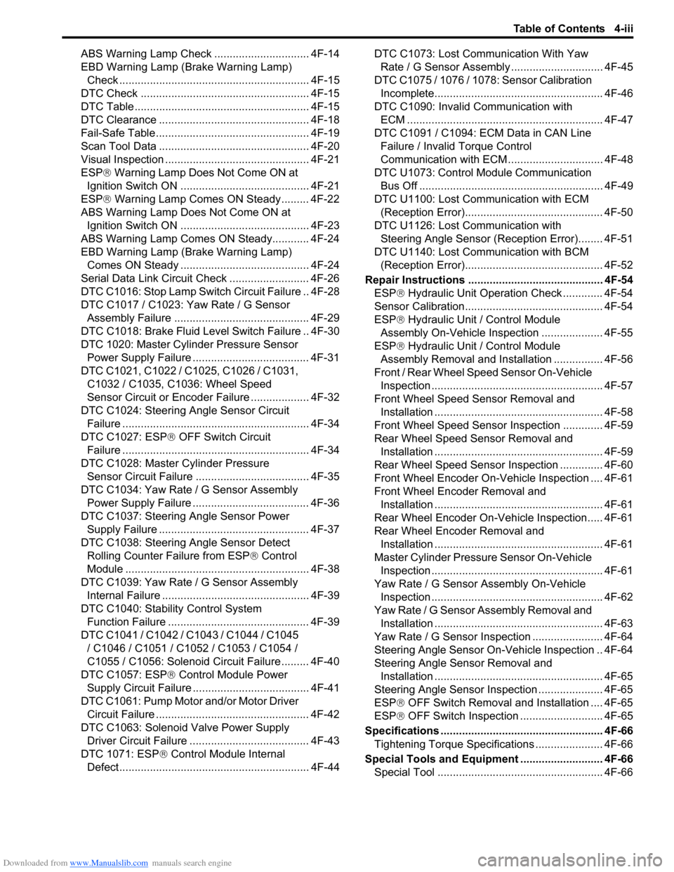
ABS Warning Lamp Check ............................... 4F-14
EBD Warning Lamp (Brake Warning Lamp) Check .............................................................. 4F-15
DTC Check ....................................................... 4F-15
DTC Table ......................................................... 4F-15
DTC Clearance ................................................. 4F-18
Fail-Safe Table ................ .................................. 4F-19
Scan Tool Data ................................................. 4F-20
Visual Inspection ............................................... 4F-21
ESP ® Warning Lamp Does Not Come ON at
Ignition Switch ON .......................................... 4F-21
ESP ® Warning Lamp Comes ON Steady......... 4F-22
ABS Warning Lamp Does Not Come ON at Ignition Switch ON .......................................... 4F-23
ABS Warning Lamp Comes ON Steady............ 4F-24
EBD Warning Lamp (Brake Warning Lamp) Comes ON Steady .......................................... 4F-24
Serial Data Link Circuit Check .......................... 4F-26
DTC C1016: Stop Lamp Swit ch Circuit Failure .. 4F-28
DTC C1017 / C1023: Yaw Rate / G Sensor Assembly Failure ............................................ 4F-29
DTC C1018: Brake Fluid Le vel Switch Failure .. 4F-30
DTC 1020: Master Cylinder Pressure Sensor Power Supply Failure ...................................... 4F-31
DTC C1021, C1022 / C1025, C1026 / C1031, C1032 / C1035, C1036: Wheel Speed
Sensor Circuit or Encode r Failure ................... 4F-32
DTC C1024: Steering Angle Sensor Circuit
Failure ............................................................. 4F-34
DTC C1027: ESP ® OFF Switch Circuit
Failure ............................................................. 4F-34
DTC C1028: Master Cylinder Pressure Sensor Circuit Failure ....... .............................. 4F-35
DTC C1034: Yaw Rate / G Sensor Assembly Power Supply Failure ...................................... 4F-36
DTC C1037: Steering Angle Sensor Power Supply Failure ................................................. 4F-37
DTC C1038: Steering Angle Sensor Detect Rolling Counter Fa ilure from ESP® Control
Module ............................................................ 4F-38
DTC C1039: Yaw Rate / G Sensor Assembly Internal Failure .............. .................................. 4F-39
DTC C1040: Stability Control System Function Failure .............................................. 4F-39
DTC C1041 / C1042 / C1043 / C1044 / C1045 / C1046 / C1051 / C1052 / C1053 / C1054 /
C1055 / C1056: Solenoid Circuit Failure ......... 4F-40
DTC C1057: ESP ® Control Module Power
Supply Circuit Failure .... .................................. 4F-41
DTC C1061: Pump Motor and/or Motor Driver Circuit Failure .................................................. 4F-42
DTC C1063: Solenoid Valve Power Supply Driver Circuit Failure ....................................... 4F-43
DTC 1071: ESP ® Control Module Internal
Defect.............................................................. 4F-44 DTC C1073: Lost Communication With Yaw
Rate / G Sensor Assembly .............................. 4F-45
DTC C1075 / 1076 / 1078: Sensor Calibration Incomplete.......................... ............................. 4F-46
DTC C1090: Invalid Communication with
ECM ................................................................ 4F-47
DTC C1091 / C1094: ECM Data in CAN Line Failure / Invalid Torque Control
Communication with ECM .. ............................. 4F-48
DTC U1073: Control Module Communication Bus Off ............................................................ 4F-49
DTC U1100: Lost Communication with ECM (Reception Error)............................................. 4F-50
DTC U1126: Lost Communication with Steering Angle Sensor (Reception Error)........ 4F-51
DTC U1140: Lost Communication with BCM (Reception Error)............................................. 4F-52
Repair Instructions ........... ................................. 4F-54
ESP® Hydraulic Unit Operation Check ............. 4F-54
Sensor Calibration............................................. 4F-54
ESP® Hydraulic Unit / Control Module
Assembly On-Vehicle Inspection .................... 4F-55
ESP ® Hydraulic
Unit / Control Module
Assembly Removal and Inst allation ................ 4F-56
Front / Rear Wheel Speed Sensor On-Vehicle Inspection ........................................................ 4F-57
Front Wheel Speed Sensor Removal and Installation ....................................................... 4F-58
Front Wheel Speed Sensor Inspection ............. 4F-59
Rear Wheel Speed Sensor Removal and Installation ....................................................... 4F-59
Rear Wheel Speed Sensor Inspection .............. 4F-60
Front Wheel Encode r On-Vehicle Inspection .... 4F-61
Front Wheel Encoder Removal and Installation ....................................................... 4F-61
Rear Wheel Encoder On-Veh icle Inspection..... 4F-61
Rear Wheel Encoder Removal and Installation ....................................................... 4F-61
Master Cylinder Pressure Sensor On-Vehicle
Inspection ........................................................ 4F-61
Yaw Rate / G Sensor Assembly On-Vehicle Inspection ........................................................ 4F-62
Yaw Rate / G Sensor Assembly Removal and Installation ....................................................... 4F-63
Yaw Rate / G Sensor Inspection ....................... 4F-64
Steering Angle Sensor On-Vehicle Inspection .. 4F-64
Steering Angle Sensor Removal and Installation ....................................................... 4F-65
Steering Angle Sensor Inspection ..................... 4F-65
ESP® OFF Switch Removal an d Installation .... 4F-65
ESP® OFF Switch Inspection ........................... 4F-65
Specifications .................... ................................. 4F-66
Tightening Torque Specifications ...................... 4F-66
Special Tools and Equipmen t ........................... 4F-66
Special Tool ...................................................... 4F-66
Page 504 of 1496
Downloaded from www.Manualslib.com manuals search engine 4A-6 Brake Control System and Diagnosis:
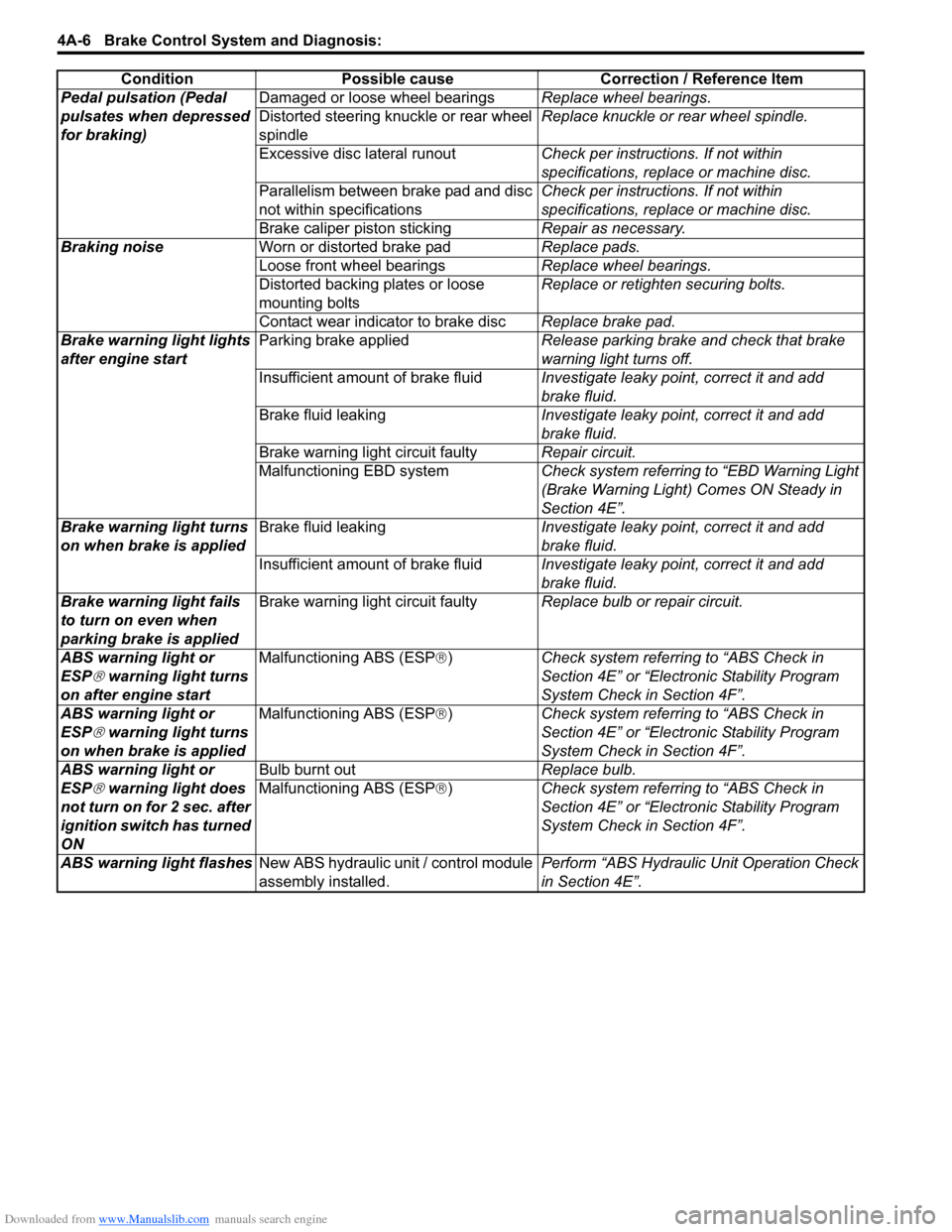
Pedal pulsation (Pedal
pulsates when depressed
for braking)Damaged or loose wheel bearings
Replace wheel bearings.
Distorted steering knuckle or rear wheel
spindle Replace knuckle or rear wheel spindle.
Excessive disc lateral runout Check per instructions. If not within
specifications, replace or machine disc.
Parallelism between brake pad and disc
not within specifications Check per instructions. If not within
specifications, replace or machine disc.
Brake caliper piston sticking Repair as necessary.
Braking noise Worn or distorted brake pad Replace pads.
Loose front wheel bearings Replace wheel bearings.
Distorted backing plates or loose
mounting bolts Replace or retighten securing bolts.
Contact wear indicator to brake disc Replace brake pad.
Brake warning light lights
after engine start Parking brake applied
Release parking brake and check that brake
warning light turns off.
Insufficient amount of brake fluid Investigate leaky point, correct it and add
brake fluid.
Brake fluid leaking Investigate leaky point, correct it and add
brake fluid.
Brake warning light circuit faulty Repair circuit.
Malfunctioning EBD system Check system referring to “EBD Warning Light
(Brake Warning Light) Comes ON Steady in
Section 4E”.
Brake warning light turns
on when brake is applied Brake fluid leaking
Investigate leaky point, correct it and add
brake fluid.
Insufficient amount of brake fluid Investigate leaky point, correct it and add
brake fluid.
Brake warning light fails
to turn on even when
parking brake is applied Brake warning light circuit faulty
Replace bulb or repair circuit.
ABS warning light or
ESP
® warning light turns
on after engine start Malfunctioning ABS (ESP
®) Check system referri ng to “ABS Check in
Section 4E” or “Electronic Stability Program
System Check in Section 4F”.
ABS warning light or
ESP
® warning light turns
on when brake is applied Malfunctioning ABS (ESP
®) Check system referri ng to “ABS Check in
Section 4E” or “Electronic Stability Program
System Check in Section 4F”.
ABS warning light or
ESP
® warning light does
not turn on for 2 sec. after
ignition switch has turned
ON Bulb burnt out
Replace bulb.
Malfunctioning ABS (ESP ®) Check system referri ng to “ABS Check in
Section 4E” or “Electronic Stability Program
System Check in Section 4F”.
ABS warning light flashes New ABS hydraulic unit / control module
assembly installed. Perform “ABS Hydraulic
Unit Operation Check
in Section 4E”.
Condition Possible cause Correction / Reference Item
Page 505 of 1496
Downloaded from www.Manualslib.com manuals search engine Brake Control System and Diagnosis: 4A-7
Repair Instructions
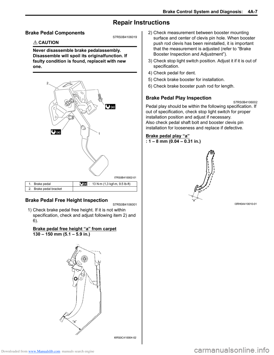
Brake Pedal ComponentsS7RS0B4106019
CAUTION!
Never disassemble brake pedalassembly.
Disassemble will spoil its originalfunction. If
faulty condition is found, replaceit with new
one.
Brake Pedal Free Height InspectionS7RS0B4106001
1) Check brake pedal free height. If it is not within specification, check and ad just following item 2) and
6).
Brake pedal free height “a” from carpet
130 – 150 mm (5.1 – 5.9 in.) 2) Check measurement between booster mounting
surface and center of clevis pin hole. When booster
push rod clevis has been reinstalled, it is important
that the measurement is adj usted (refer to “Brake
Booster Inspection and Adjustment”).
3) Check stop light switch position . Adjust it if it is out of
specification.
4) Check pedal for dent.
5) Check brake booster for installation.
6) Check brake booster push rod for length.
Brake Pedal Play InspectionS7RS0B4106002
Pedal play should be within the following specification. If
out of specification, check stop light switch for proper
installation position and adjust if necessary.
Also check pedal shaft bolt and booster clevis pin
installation for looseness and replace if defective.
Brake pedal play
“a”
: 1 – 8 mm (0.04 – 0.31 in.)
1. Brake pedal : 13 N⋅m (1,3 kgf-m, 9.5 lb-ft)
2. Brake pedal bracket
(a) 1
2
(a)
I7RS0B410002-01
I6RS0C410004-02
“a”I3RH0A410010-01
Page 506 of 1496
Downloaded from www.Manualslib.com manuals search engine 4A-8 Brake Control System and Diagnosis:
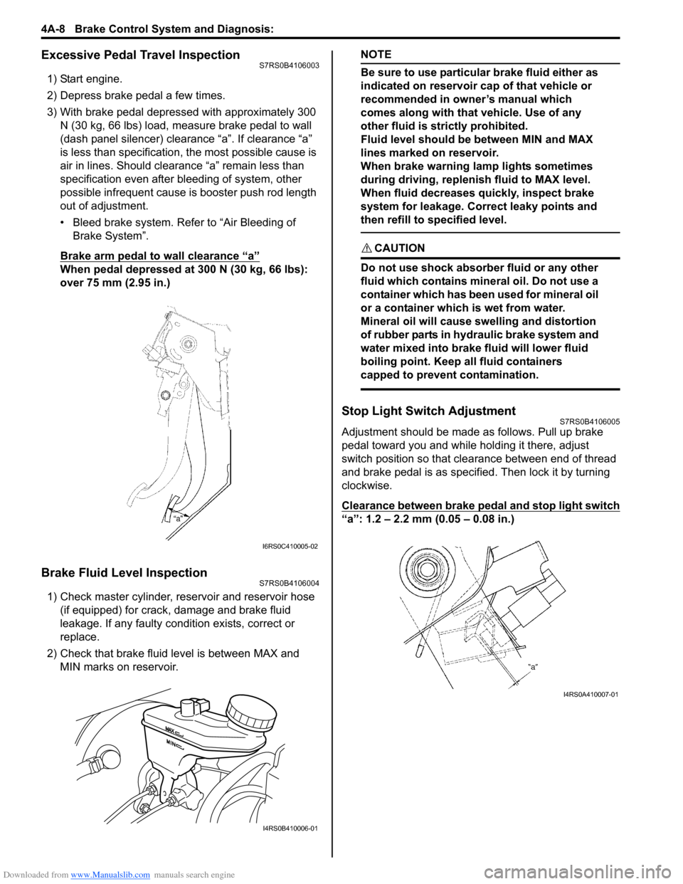
Excessive Pedal Travel InspectionS7RS0B4106003
1) Start engine.
2) Depress brake pedal a few times.
3) With brake pedal depressed with approximately 300 N (30 kg, 66 lbs) load, measure brake pedal to wall
(dash panel silencer) clearance “a”. If clearance “a”
is less than specification, the most possible cause is
air in lines. Should clearance “a” remain less than
specification even after bleeding of system, other
possible infrequent cause is booster push rod length
out of adjustment.
• Bleed brake system. Refer to “Air Bleeding of Brake System”.
Brake arm pedal to wall clearance “a”
When pedal depressed at 300 N (30 kg, 66 lbs):
over 75 mm (2.95 in.)
Brake Fluid Level InspectionS7RS0B4106004
1) Check master cylinder, reservoir and reservoir hose (if equipped) for crack, damage and brake fluid
leakage. If any faulty condition exists, correct or
replace.
2) Check that brake fluid level is between MAX and MIN marks on reservoir.
NOTE
Be sure to use particular brake fluid either as
indicated on reservoir cap of that vehicle or
recommended in owner’s manual which
comes along with that vehicle. Use of any
other fluid is strictly prohibited.
Fluid level should be between MIN and MAX
lines marked on reservoir.
When brake warning lamp lights sometimes
during driving, replenis h fluid to MAX level.
When fluid decreases quickly, inspect brake
system for leakage. Correct leaky points and
then refill to specified level.
CAUTION!
Do not use shock absorber fluid or any other
fluid which contains mineral oil. Do not use a
container which has been used for mineral oil
or a container which is wet from water.
Mineral oil will cause swelling and distortion
of rubber parts in hydraulic brake system and
water mixed into brake fluid will lower fluid
boiling point. Keep all fluid containers
capped to prevent contamination.
Stop Light Switch AdjustmentS7RS0B4106005
Adjustment should be made as follows. Pull up brake
pedal toward you and while holding it there, adjust
switch position so that clea rance between end of thread
and brake pedal is as specified. Then lock it by turning
clockwise.
Clearance between brake pedal and stop light switch
“a”: 1.2 – 2.2 mm (0.05 – 0.08 in.)
I6RS0C410005-02
I4RS0B410006-01
I4RS0A410007-01
Page 511 of 1496
Downloaded from www.Manualslib.com manuals search engine Brake Control System and Diagnosis: 4A-13
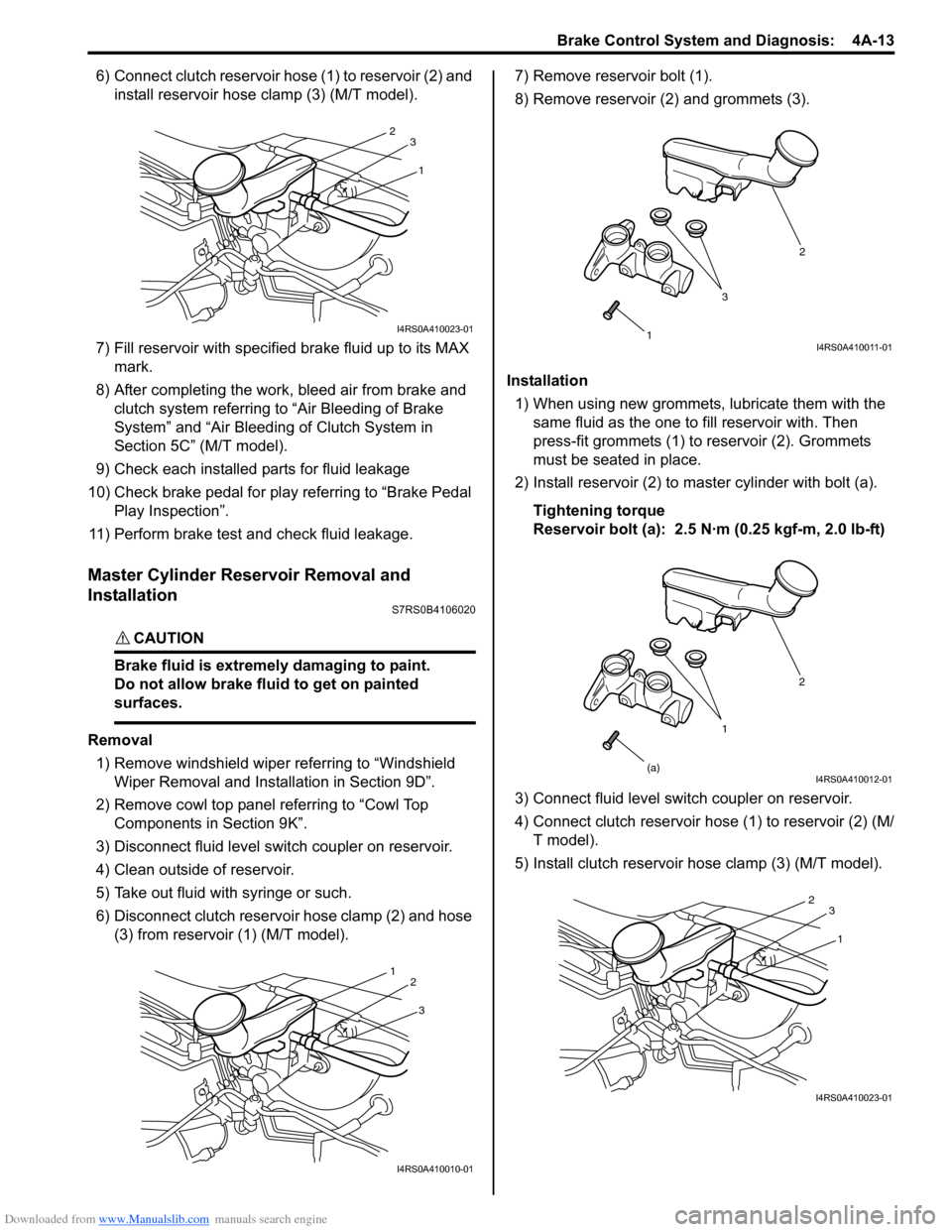
6) Connect clutch reservoir hose (1) to reservoir (2) and install reservoir hose clamp (3) (M/T model).
7) Fill reservoir with specified brake fluid up to its MAX
mark.
8) After completing the work, bleed air from brake and clutch system referring to “Air Bleeding of Brake
System” and “Air Bleeding of Clutch System in
Section 5C” (M/T model).
9) Check each installed parts for fluid leakage
10) Check brake pedal for play referring to “Brake Pedal Play Inspection”.
11) Perform brake test and check fluid leakage.
Master Cylinder Reservoir Removal and
Installation
S7RS0B4106020
CAUTION!
Brake fluid is extremely damaging to paint.
Do not allow brake fluid to get on painted
surfaces.
Removal 1) Remove windshield wiper referring to “Windshield Wiper Removal and Insta llation in Section 9D”.
2) Remove cowl top panel referring to “Cowl Top Components in Section 9K”.
3) Disconnect fluid level s witch coupler on reservoir.
4) Clean outside of reservoir.
5) Take out fluid with syringe or such.
6) Disconnect clutch reservoir hose clamp (2) and hose (3) from reservoir (1) (M/T model). 7) Remove reservoir bolt (1).
8) Remove reservoir (2) and grommets (3).
Installation 1) When using new grommets, lubricate them with the same fluid as the one to fill reservoir with. Then
press-fit grommets (1) to reservoir (2). Grommets
must be seated in place.
2) Install reservoir (2) to master cylinder with bolt (a).
Tightening torque
Reservoir bolt (a): 2.5 N·m (0.25 kgf-m, 2.0 lb-ft)
3) Connect fluid level switch coupler on reservoir.
4) Connect clutch reservoir hose (1) to reservoir (2) (M/ T model).
5) Install clutch reservoir hose clamp (3) (M/T model).
1
2
3
I4RS0A410023-01
3
1
2
I4RS0A410010-01
1 2
3I4RS0A410011-01
1 2
(a)
I4RS0A410012-01
1
2
3
I4RS0A410023-01
Page 549 of 1496

Downloaded from www.Manualslib.com manuals search engine ABS: 4E-10
Problem symptom confirmation
Check if what the customer claimed in “Customer
Questionnaire” is actually found in the vehicle and if that
symptom is found, whether it is identified as a failure.
(This step should be shared with the customer if
possible.) Check warning lights related to brake system
referring to “EBD Warning Light (Brake Warning Light)
Check” and “ABS Warning Light Check”.
DTC check, record and clearance
Perform “DTC Check” proced ure, record it and then
clear it referring to “DTC Clearance”.
Recheck DTC referring to “DTC Check”.
When DTC which is recorded at DTC check procedure is
detected again after performi ng DTC clearance, go to
“Step 4: ABS Check: ” to proceed the diagnosis.
When DTC which is recorded at DTC check procedure is
not indicated anymore after performing DTC clearance,
ABS control module does not perform the system
diagnosis, or temporary abnormality may occur,
therefore go to “Step 2: Driving Test: ” to proceed the
diagnosis.
Step 2: Driving Test
Test drive the vehicle at 40 km/h for more than a minute
and check if any trouble symptom (such as abnormal
lighting of ABS warn ing light) exists.
If the malfunction DTC is co nfirmed again at ignition
switch ON, driving test as described is not necessary.
Proceed to Step 3.
Step 3: DTC Check
Recheck DTC referring to “DTC Check”.
Step 4: ABS Check
According to ABS Check for the DTC confirmation in
Step 3, locate the cause of the trouble, namely in a
sensor, switch, wire harness, connector, actuator
assembly or other part and repair or replace faulty parts.
Step 5: Brakes Diagnosis
Check the parts or system suspected as a possible
cause referring to “Brakes Symptom Diagnosis in
Section 4A” and based on symptoms appearing on the
vehicle (symptom obtained through Steps 1 and 2 and
repair or replace faulty parts, if any).
Step 6: Check for Intermittent Problem
Check parts where an intermittent trouble is easy to
occur (e.g., wire harness, con nector, etc.), referring to
“Intermittent and Poor Connection Inspection in Section
00” and related circuit of trouble code recorded in Step 1
to 3.
Step 7: Final Confirmation Test
Confirm that the problem symptom has gone and the
ABS is free from any abnormal conditions. If what has
been repaired is related to the malfunction DTC, clear
the DTC once referring to “DTC Clearance” and perform
test driving and confirm that no DTC is indicated.ABS Warning Light CheckS7RS0B4504002
1) Turn ignition switch ON.
2) Check that ABS warning light (1) comes ON for
about 2 seconds and then goes off.
If any faulty condition is found, advance to “ABS
Warning Light Does Not Come ON at Ignition Switch
ON” or “ABS Warning Light Comes ON Steady”.
EBD Warning Light (Brake Warning Light)
Check
S7RS0B4504003
NOTE
Perform this check on a level place.
1) Turn ignition switch ON with parking brake applied.
2) Check that EBD warning lig ht (brake warning light)
(1) is turned ON.
3) Release parking brake with ignition switch ON and check that EBD warning lig ht (brake warning light)
goes off.
If it doesn’t go off, go to “EBD Warning Light (Brake
Warning Light) Comes ON Steady”.
11
I4RS0A450007-01
BRAKE
1
I4RS0A450008-01
Page 551 of 1496

Downloaded from www.Manualslib.com manuals search engine ABS: 4E-12
DTC ClearanceS7RS0B4504006
WARNING!
When performing a driving test, select a safe
place where there is neither any traffic nor
any traffic accident possibility and be very
careful during testing to avoid occurrence of
an accident.
After repair or replace malfunction part(s), clear all DTCs
by performing the following procedure or using SUZUKI
scan tool.
1) Connect SUZUKI scan tool to data link connector in the same manner as when making this connection
for DTC check.
2) Turn ignition switch to ON position.
3) Erase DTC according to instructions displayed on scan tool. Refer to scan tool operator’s manual for
further derails.
NOTE
For DTC C 1021, C1022, C1025, C1026, C1031,
C1032, C1035, C1036 and C1061, confirm that
ABS warning light turns off after performing
Step 2 of “Test Driving” under “ABS Check”,
and then clear the DTCs.
4) After completing the clear ance, turn ignition switch
OFF and disconnect scan tool from data link
connector.
5) Perform “Driving Test” (S tep 2 of “ABS Check”) and
“DTC Check” and confirm that NO DTC is displayed
on scan tool.
Scan Tool DataS7RS0B4504007
The parameter data below are values measured with the
scan tool when the normally operating vehicle is under
the following conditions. When taking measurements for
comparison by using the scan tool, be sure to check that
the vehicle is under the following conditions.
• Apply parking brake and block wheels.
• Ignition switch ON.
• Turn OFF air conditioner (if equipped).
• Apply no load to power steering (if equipped). (Don’t turn it)
• Turn OFF all electric loads (except ignition).
• No DTC.
• ABS is not operated. (N ormal braking operation)
Scan Tool Data Definition
Battery Volt (V): Battery Voltage is an analog input
signal read by the ABS control module. Certain ABS
control module function s will be modified if the
battery voltage falls below or rises above
programmed thresholds.
Pump Motor Driver (V): This parameter indicates the
operational condition of the pump motor driver
(transistor).
RF Wheel Speed, LF Wheel Speed, RR Wheel Speed and LF Wheel Speed (km/h, MPH): Wheel speed
is an ABS control module inte rnal parameter. It is
computed by reference pulses from the wheel speed
sensor.
Brake Switch (ON, OFF): This switch signal informs
the ABS control modu le whether the brake is active
or not.
Scan Tool
Data Standards Condition
Battery
Voltage 10.0 – 18.0 V —
Pump Motor
Driver 0.0 V —
RF Wheel
Sp ee d 0 km/h, 0.0 MPH Vehicle stop
LF Wheel
Sp ee d 0 km/h, 0.0 MPH Vehicle stop
RR Wheel
Sp ee d 0 km/h, 0.0 MPH Vehicle stop
LR Wheel
Sp ee d 0 km/h, 0.0 MPH Vehicle stop
Brake Switch ONBrake pedal
depressed
OFF Brake pedal released