Page 700 of 1496
Downloaded from www.Manualslib.com manuals search engine 5A-56 Automatic Transmission/Transaxle:
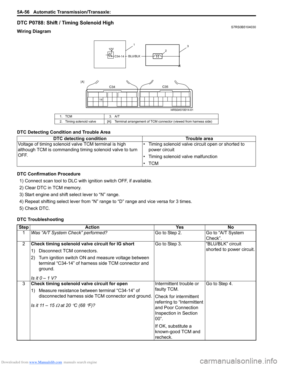
DTC P0788: Shift / Timing Solenoid HighS7RS0B5104030
Wiring Diagram
DTC Detecting Condition and Trouble Area
DTC Confirmation Procedure
1) Connect scan tool to DLC with ig nition switch OFF, if available.
2) Clear DTC in TCM memory.
3) Start engine and shift select lever to “N” range.
4) Repeat shifting select lever from “N” range to “D” range and vice versa for 3 times.
5) Check DTC.
DTC Troubleshooting
1. TCM 3. A/T
2. Timing solenoid valve [A]: Terminal arrangement of TCM connector (viewed from harness side)
DTC detecting condition Trouble area
Voltage of timing solenoid valve TCM terminal is high
although TCM is commanding timing solenoid valve to turn
OFF. • Timing solenoid valve circuit open or shorted to
power circuit
• Timing solenoid valve malfunction
•TCM
12V
C34-14BLU/BLK
31
2
14
C34C35
[A]
I4RS0A510014-01
Step Action YesNo
1 Was “A/T System Check” performed? Go to Step 2.Go to “A/T System
Check”.
2 Check timing solenoid valve circuit for IG short
1) Disconnect TCM connectors.
2) Turn ignition switch ON and measure voltage between
terminal “C34-14” of harness side TCM connector and
ground.
Is it 0 – 1 V? Go to Step 3.
“BLU/BLK” circuit
shorted to power circuit.
3 Check timing solenoid valve circuit for open
1) Measure resistance between terminal “C34-14” of
disconnected harness side TCM connector and ground.
Is it 11 – 15
Ω at 20 °C (68 °F)? Intermittent trouble or
faulty TCM.
Check for intermittent
referring to “Intermittent
and Poor Connection
Inspection in Section
00”.
If OK, substitute a
known-good TCM and
recheck.Go to Step 4.
Page 702 of 1496
Downloaded from www.Manualslib.com manuals search engine 5A-58 Automatic Transmission/Transaxle:
DTC P0961: Pressure Control Solenoid “A” Control Circuit Range / PerformanceS7RS0B5104049
Wiring Diagram
DTC Detecting Condition and Trouble Area
DTC Confirmation Procedure
1) Connect scan tool to DLC with ignition switch turned OFF.
2) Clear DTC in TCM memory.
3) Start engine.
4) Keep engine running at idle speed for 30 seconds or more.
5) Stop vehicle and check DTC.
1. TCM 3. A/T
2. Pressure control solenoid valve [A]: Terminal arrangement of TCM connector (viewed from harness side)
DTC detecting condition Trouble area
Difference between target current of control solenoid valve
circuit and monitor current of control solenoid valve circuit
is more than specification. • Malfunction of pressure control solenoid valve or its
circuit malfunction
•TCM
12V
C34-4
C34-2
GRY
LT GRN/BLK
3
1
2
42
C34C35
[A]
I4RS0A510015-01
Page 704 of 1496
Downloaded from www.Manualslib.com manuals search engine 5A-60 Automatic Transmission/Transaxle:
DTC P0962: Pressure Control Solenoid “A” Control Circuit LowS7RS0B5104031
Wiring Diagram
DTC Detecting Condition and Trouble Area
DTC Confirmation Procedure
1) Connect scan tool to DLC with ig nition switch OFF, if available.
2) Clear DTC in TCM memory.
3) Start engine.
4) Keep engine running at idle speed for 30 seconds or more.
5) Stop vehicle and check DTC.
1. TCM 3. A/T
2. Pressure control solenoid valve [A]: Terminal arrangement of TCM connector (viewed from harness side)
DTC detecting condition Trouble area
Pressure control solenoid valv e output voltage is too low
comparing with TCM command value. • Pressure control solenoid valve circuit open or
shorted to ground
• Malfunction of pressure control solenoid valve
•TCM
12V
C34-4
C34-2
GRY
LT GRN/BLK
3
1
2
42
C34C35
[A]
I4RS0A510015-01
Page 706 of 1496
Downloaded from www.Manualslib.com manuals search engine 5A-62 Automatic Transmission/Transaxle:
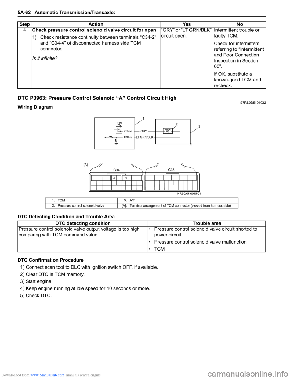
DTC P0963: Pressure Control Solenoid “A” Control Circuit HighS7RS0B5104032
Wiring Diagram
DTC Detecting Condition and Trouble Area
DTC Confirmation Procedure
1) Connect scan tool to DLC with ig nition switch OFF, if available.
2) Clear DTC in TCM memory.
3) Start engine.
4) Keep engine running at idle speed for 10 seconds or more.
5) Check DTC. 4
Check pressure control solenoid valve circuit for open
1) Check resistance continuity between terminals “C34-2”
and “C34-4” of disconnected harness side TCM
connector.
Is it infinite? “GRY” or “LT GRN/BLK”
circuit open.
Intermittent trouble or
faulty TCM.
Check for intermittent
referring to “Intermittent
and Poor Connection
Inspection in Section
00”.
If OK, substitute a
known-good TCM and
recheck.
Step Action Yes No
1. TCM
3. A/T
2. Pressure control solenoid valve [A]: Terminal arrangement of TCM connector (viewed from harness side)
DTC detecting condition Trouble area
Pressure control solenoid valve output voltage is too high
comparing with TCM command value. • Pressure control solenoid valve circuit shorted to
power circuit
• Pressure control solenoid valve malfunction
•TCM
12V
C34-4
C34-2
GRY
LT GRN/BLK
3
1
2
42
C34C35
[A]
I4RS0A510015-01
Page 708 of 1496
Downloaded from www.Manualslib.com manuals search engine 5A-64 Automatic Transmission/Transaxle:
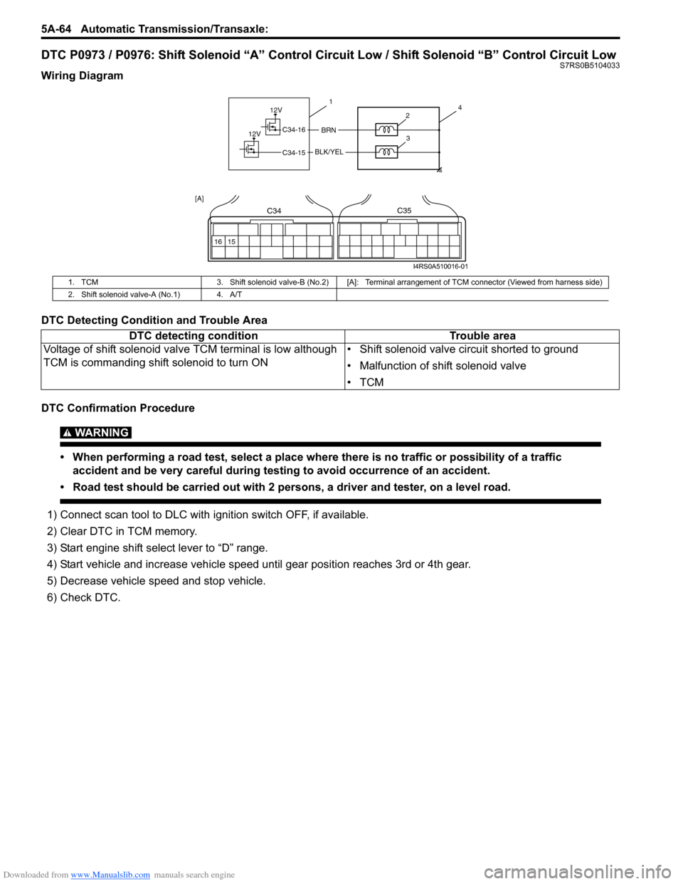
DTC P0973 / P0976: Shift Solenoid “A” Control Circuit Low / Shift Solenoid “B” Control Circuit LowS7RS0B5104033
Wiring Diagram
DTC Detecting Condition and Trouble Area
DTC Confirmation Procedure
WARNING!
• When performing a road test, select a place where there is no traffic or possibility of a traffic
accident and be very careful during testing to avoid occurrence of an accident.
• Road test should be carried out with 2 persons, a driver and tester, on a level road.
1) Connect scan tool to DLC with ig nition switch OFF, if available.
2) Clear DTC in TCM memory.
3) Start engine shift select lever to “D” range.
4) Start vehicle and increase vehicle speed until gear position reaches 3rd or 4th gear.
5) Decrease vehicle sp eed and stop vehicle.
6) Check DTC.
1. TCM 3. Shift solenoid valve-B (No.2) [A]: Terminal arr angement of TCM connector (Viewed from harness side)
2. Shift solenoid valve-A (No.1) 4. A/T
DTC detecting condition Trouble area
Voltage of shift solenoid valv e TCM terminal is low although
TCM is commanding shift solenoid to turn ON • Shift solenoid valve circuit shorted to ground
• Malfunction of shift solenoid valve
•TCM
12V
12VBRNC34-16
C34-15BLK/YEL
41
2
3
16 15
C34C35
[A]
I4RS0A510016-01
Page 710 of 1496
Downloaded from www.Manualslib.com manuals search engine 5A-66 Automatic Transmission/Transaxle:
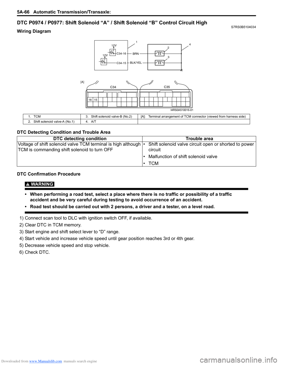
DTC P0974 / P0977: Shift Solenoid “A” / Shift Solenoid “B” Control Circuit HighS7RS0B5104034
Wiring Diagram
DTC Detecting Condition and Trouble Area
DTC Confirmation Procedure
WARNING!
• When performing a road test, select a place where there is no traffic or possibility of a traffic
accident and be very careful during testing to avoid occurrence of an accident.
• Road test should be carried out with 2 persons, a driver and a tester, on a level road.
1) Connect scan tool to DLC with ig nition switch OFF, if available.
2) Clear DTC in TCM memory.
3) Start engine and shift select lever to “D” range.
4) Start vehicle and increase vehicle speed until gear position reaches 3rd or 4th gear.
5) Decrease vehicle sp eed and stop vehicle.
6) Check DTC.
1. TCM 3. Shift solenoid valve-B (No.2) [A]: Terminal arra ngement of TCM connector (viewed from harness side)
2. Shift solenoid valve-A (No.1) 4. A/T
DTC detecting condition Trouble area
Voltage of shift solenoid valve TCM terminal is high although
TCM is commanding shift solenoid to turn OFF • Shift solenoid valve circuit open or shorted to power
circuit
• Malfunction of shift solenoid valve
•TCM
12V
12VBRNC34-16
C34-15BLK/YEL
41
2
3
16 15
C34C35
[A]
I4RS0A510016-01
Page 713 of 1496
Downloaded from www.Manualslib.com manuals search engine Automatic Transmission/Transaxle: 5A-69
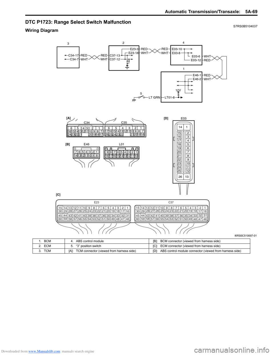
DTC P1723: Range Select Switch MalfunctionS7RS0B5104037
Wiring Diagram
LT01-8
12V
LT GRN
5
REDWHTE03-6E03-12
1
2
REDWHT
4
[D]
[C] [B]
E46
1234567
891011121314
REDWHTC37-13C37-12REDWHTC34-17C34-7
3
32
1110 9
212019 87
18
165
1615 14131211 43
2423 2122 10 9 8 7
21
1920 1817
C3417 16
26 2515 14
654
13 12
23 2224 C35
[A]
E23-3E23-18REDWHTE03-10E03-8
REDWHTE46-1E46-2
E03
15
16
17
18
19
20
21
22
23
24
25 2
3
4
5
6
7
8
9
10
11
12
1
13
14
26
E23C37
34
1819
567
1011
17
20
47 46
495051
2122
52 16
25 9
24
14
29
5557 54 53
59
60 58 2
262728
15
30
56 4832 31
34353637
4042 39 38
44
45 43 41 33 1
1213
238
34
1819
567
1011
17
20
47 46
495051
2122
52 16
25 9
24
14
29
5557 54 53
59
60 58 2
262728
15
30
56 4832 31
34353637
4042 39 38
44
45 43 41 331
1213
238
L01
678
9 54321
15161718 14 13 12 1110
I6RS0C510007-01
1. BCM
4. ABS control module [B]: BCM connector (viewed from harness side)
2. ECM 5. “3” position switch [C]: ECM connector (viewed from harness side)
3. TCM [A]: TCM connector (viewed from harness side) [D]: ABS control module connector (viewed from harness side)
Page 715 of 1496
Downloaded from www.Manualslib.com manuals search engine Automatic Transmission/Transaxle: 5A-71
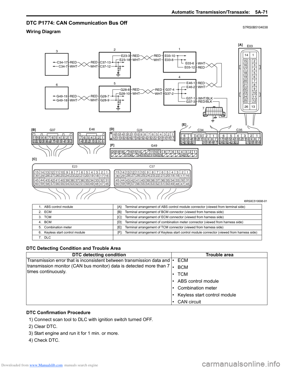
DTC P1774: CAN Communication Bus OffS7RS0B5104038
Wiring Diagram
DTC Detecting Condition and Trouble Area
DTC Confirmation Procedure1) Connect scan tool to DLC with ignition switch turned OFF.
2) Clear DTC.
3) Start engine and run it for 1 min. or more.
4) Check DTC.
REDWHTE03-6E03-12
1
4
7
REDWHT
2
[C]
[B]
G37E46
1234567
1234567
891011
891011
121314 121314
151617
18
19202122 [E]65
1615 14131211 43
2423 2122 10 9 8 7
21
1920 1817
C3417 16
26 2515 14
65 3
42
13 12
23 2224 1110 9
212019 87
18
1
C35
[F]
REDWHTC37-13C37-12REDWHTC34-17C34-7
3
1234567891011
141516
36 34 33 32 31 30 29 24 23
37
181920
[D] [A]
G49
E23-3E23-18
5
REDWHTG28-7G28-9REDWHTG49-19G49-18
6
REDWHTE03-10E03-8
G37-4G37-2
REDWHTE46-1E46-2REDWHTREDWHTG28-8G28-10
RED/BLKWHT/BLKG37-3G37-1
E03
15
16
17
18
19
20
21
22
23
24
25 2
3
4
5
6
7
8
9
10
11
12
1
13
14
26
E23C37
34
1819
567
1011
17
20
47 46
495051
2122
52 16
25 9
24
14
29
5557 54 53
59
60 58 2
262728
15
30
56 4832 31
34353637
4042 39 38
44
45 43 41 33 1
1213
238
34
1819
567
1011
17
20
47 46
495051
2122
52 16
25 9
24
14
29
5557 54 53
59
60 58 2
262728
15
30
56 4832 31
34353637
4042 39 38
44
45 43 41 331
1213
238
G281234567
8
910111213141516
1718
19
20
212223242526272829303132
I6RS0C510008-01
1. ABS control module [A]: Terminal arrangement of ABS control module connector (viewed from terminal side)
2. ECM [B]: Terminal arrangement of BCM connector (viewed from harness side)
3. TCM [C]: Terminal arrangement of ECM connector (viewed from harness side)
4. BCM [D]: Terminal arrangement of combination meter connector (viewed from harness side)
5. Combination meter [E]: Terminal arrangement of TCM connector (viewed from harness side)
6. Keyless start control module [F]: Terminal arrangement of Keyless start control module connector (viewed from harness side)
7. DLC
DTC detecting condition Trouble area
Transmission error that is incons istent between transmission data and
transmission monitor (CAN bus monitor) data is detected more than 7
times continuously. •ECM
•BCM
•TCM
• ABS control module
• Combination meter
• Keyless start control module
• CAN circuit