2008 SUZUKI SWIFT idle
[x] Cancel search: idlePage 831 of 1496

Downloaded from www.Manualslib.com manuals search engine Manual Transmission/Transaxle: 5B-17
5) Remove gear shift locating bolts (1) with washers,
then take out locating springs and steel balls.
6) Remove back up light switch (2).
7) Remove reverse shaft bolt (2) with washer.
8) Remove case bolts (1) from outside and another bolts from clutch housing side.
9) Tapping left case flanges with plastic hammer, remove left case (3).
10) Pull out reverse gear shaft (1) with washer (2), then take off reverse idler gear (3).
11) Remove reverse gear shift lever bolts (4) and reverse gear shift lever (5).
12) Pull out 5th & reverse gear shift guide shaft (6) together with 5th & reverse gear shift shaft (7). 13) Tapping input shaft end with plastic hammer, push it
out as assembly from case a little, then take out
input shaft assembly (1), countershaft assembly (2),
high speed gear shift shaft (3) and low speed gear
shift shaft (4) all at once.
14) Remove countershaft left bearing outer race from left case (1) using special tool.
Special tool
(A): 09913–70123
15) Remove side bearing retainer bolts.
16) Turn side bearing retainer (1) counterclockwise until it stops, and remove side bearing retainer using 2 flat
end rods (2) or the like.
17) Remove O-ring from side bearing retainer.
I2RH01520032-01
I4RS0A520032-01
I4RS0A520033-01
I2RH01520035-01
(A)
1
I4RH01520021-01
1
2
2
I4RS0A520034-01
Page 833 of 1496

Downloaded from www.Manualslib.com manuals search engine Manual Transmission/Transaxle: 5B-19
4) Make reverse idler gear (1) with reverse gear shift lever (2), insert reverse gear shaft (3) into case (4)
through idler gear and then align “A” in shaft with “B”
in case.
5) Fasten reverse gear shift lever bolts after applying thread lock cement.
: Thread lock cement 99000–32110 (Thread Lock
Cement Super 1322)
Tightening torque
Reverse gear shift lever bolt: 23 N·m (2.3 kgf-m,
17.0 lb-ft)
NOTE
• Make sure that washer (5) has been installed in shaft at above the gear.
• Check to confirm that reverse gear shift lever end has clearance “a” to idler gear
groove.
Distance between lever and idler gear shaft
“a”: 0.5 – 1.0 mm (0.02 – 0.04 in.) 6) Clean mating surfaces of both right and left cases,
apply sealant to right case (2) as shown in the figure
by such amount that its section is 1.5 mm (0.059 in.)
in diameter then mate it with left case (1).
“B”: Sealant 99000–31260 (SUZUKI Bond
No.1217G)
7) Install reverse shaft bolt (4) to which thread lock cement has been applied, with aluminum washer
and tighten it to specified torque.
“A”: Thread lock cement 99000–32110 (Thread
Lock Cement Super 1322)
Tightening torque
Reverse shaft bolt (c): 23 N·m (2.3 kgf-m, 17.0
lb-ft)
8) Tighten case bolts (3) from outside tighten another case bolts from clutch housing side to specified
torque.
Tightening torque
Transaxle case bolt (b): 23 N·m (2.3 kgf-m, 17.0
lb-ft)
I4RS0A520036-01
I3RM0A520043-01
Page 855 of 1496

Downloaded from www.Manualslib.com manuals search engine Clutch: 5C-3
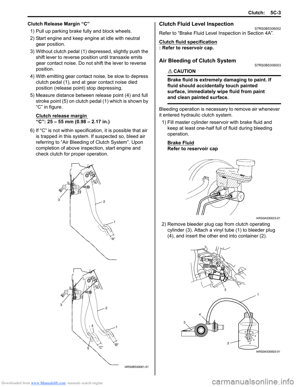
Clutch Release Margin “C”1) Pull up parking brake fully and block wheels.
2) Start engine and keep engine at idle with neutral gear position.
3) Without clutch pedal (1) dep ressed, slightly push the
shift lever to re verse position until transaxle emits
gear contact noise. Do not shift the lever to reverse
position.
4) With emitting gear contact noise, be slow to depress clutch pedal (1), and at gear contact noise died
position (release point) stop depressing.
5) Measure distance between release point (4) and full stroke point (5) on clutch pedal (1) which is shown by
“C” in figure.
Clutch release margin
“C”: 25 – 55 mm (0.98 – 2.17 in.)
6) If “C” is not within specificat ion, it is possible that air
is trapped in this system. If suspected so, bleed air
referring to “Air Bleeding of Clutch System”. Upon
completion of above inspection, start engine and
check clutch for proper operation.
Clutch Fluid Level InspectionS7RS0B5306002
Refer to “Brake Fluid Level Inspection in Section 4A”.
Clutch fluid specification
: Refer to reservoir cap.
Air Bleeding of Clutch SystemS7RS0B5306003
CAUTION!
Brake fluid is extremely damaging to paint. If
fluid should accidentally touch painted
surface, immediately wipe fluid from paint
and clean painted surface.
Bleeding operation is necessary to remove air whenever
it entered hydraulic clutch system.
1) Fill master cylinder reservoir with brake fluid and keep at least one-half full of fluid during bleeding
operation.
Brake Fluid
Refer to reservoir cap
2) Remove bleeder plug cap from clutch operating cylinder (3). Attach a vinyl tube (1) to bleeder plug
(4), and insert the other end into container (2).
2
1
“A”
3
2
1
3
“B”
“C”
4
5
I4RS0B530001-01
I4RS0A530023-01
3 4 1
2
3
I4RS0A530003-01
Page 887 of 1496

Downloaded from www.Manualslib.com manuals search engine Power Assisted Steering System: 6C-5
Terminal Arrangement of P/S Control Module Coupler (Viewed from Harness Side)
Diagnostic Information and Procedures
EPS System CheckS7RS0B6304001
WARNING!
Carry out test drive in light traffic area to prevent an accident.
Refer to the following items for the details of each step.Terminal Circuit Terminal Circuit
E49-1 Main power supply for internal memory
and EPS motor E52-9 Ground for torque sensors
E49-2 Ground for P/S control module E52-10 —
E51-1 Motor output 1 E52-11 Serial communication for data link
connector
E51-2 Motor output 2 E52-12 Engine speed signal
E52-1 Ignition switch signal for P/S control
module E52-13 —
E52-2 — E52-14 P/S operation signal (idle up signal)
E52-3 — E52-15 —
E52-4 Vehicle speed signal E52-16 Torque sensor internal failure signal
E52-5 “EPS” warning light E52-17 —
E52-6 Torque sensor signal (Sub) E52-18 Torque sensor signal (Main)
E52-7 — E52-19 Ground for shield wire
E52-8 Main power supply for torque sensor E52-20 5 V reference power supply for torque
sensor
Step
Action YesNo
1 �) Customer complaint analysis
1) Perform customer complaint analysis referring to “Customer Complaint Analysis”.
Was customer complaint analysis performed? Go to Step 2.
Perform customer
complaint analysis.
2 �) DTC check, record and clearance
1) Check for DTC (including pending DTC) referring to “DTC Check”, Record and Clearance.
Is there any DTC(s)? Print DTC or write them
down and clear them by
referring to “DTC
Clearance” and go to
St ep 3 .Go to Step 4.
3 �) Visual inspection
1) Perform visual inspection referring to “Visual Inspection”.
Is there any faulty condition? Repair or replace
malfunction part, and go
to Step 11.
Go to Step 5.
4 �) Visual inspection
1) Perform visual inspection referring to “Visual Inspection”.
Is there any faulty condition? Repair or replace
malfunction part, and go
to Step 11.
Go to Step 8.
5 �) Trouble symptom confirmation
1) Confirm trouble symptom referring to “Trouble Symptom Confirmation”.
Is trouble symptom identified? Go to Step 6.
Go to Step 7.
6 �) Rechecking and record of DTC
1) Recheck for DTC referring to “DTC Check”.
Is there any DTC(s)? Go to Step 9.
Go to Step 8.
Page 893 of 1496

Downloaded from www.Manualslib.com manuals search engine Power Assisted Steering System: 6C-11
Scan Tool DataS7RS0B6304006
NOTE
When P/S motor is cold condition (that is, armature coil of P/S motor is not heated), normal value with
asterisk (*) mark in the following table is displayed on scan tool.
�) C1143 P/S motor circuit current too
high Measured motor drive current is
more than 50 A.
• P/S motor circuit
• P/S motor
• P/S control module1 driving
cycle
�) C1145 P/S motor circuit current too
low Measured motor drive current is
less than 2 A continuously for
more than 3 seconds even though
target motor drive current is more
than 4 A.
or
Measured motor drive current is
less than 0.8 A for total 1 second
even though motor control duty is
more than 90% while target motor
drive current is less than 8 A. 1 driving
cycle
�) C1153 P/S control module power
supply circuit Power supply voltage of P/S
control module is less than 9 V for
5 seconds continuously. • P/S control module power
supply circuit
• Undercharged Battery
• P/S control module 1 driving
cycle
�) C1155 P/S control module internal
failure Internal memory (EEPROM) is
data error.
• P/S control moduleNot
applicable
Internal circuit is faulty.
or
Power supply voltage of P/S
control module exceeded 17.5 V. • Overcharged Battery
• P/S control module
1 driving
cycle
DTC No. Detecting item
Detecting condition
(DTC will set when detecting) Trouble area MIL
Scan tool data
Vehicle conditionNormal condition
�) Battery Voltage
Ignition switch ON 10 – 14 V
�) TQS Power Supply 10 – 14 V
�) TQS Main Torque Engine running at idle speed Steering wheel at fully turned to left –9.4 – 0 N
⋅m
Steering wheel at free 0 N⋅m
Steering wheel at fully turned to right 0 – 9.4 N ⋅m
�) TQS Sub Torque Engine running at idle speed Steering wheel at fully turned to left –9.4 – 0 N
⋅m
Steering wheel at free 0 N⋅m
Steering wheel at fully turned to right 0 – 9.4 N ⋅m
�) Assist Torque Engine running at idle speed Steering wheel at fully turned to left –9.4 – 0 N
⋅m
Steering wheel at free 0 N⋅m
Steering wheel at fully turned to right 0 – 9.4 N ⋅m
�) Motor Control Engine running at idle speed Steering wheel at free
0 A
Steering wheel at fully turned to left or right *35 – 45 A
�) Motor Monitor Engine running at idle speed Steering wheel at free
0 A
Steering wheel at fully turned to left or right *35 – 45 A
�) Vehicle Speed Engine running and vehicle at stop 0 km/h
�) Engine Speed Engine running at idle speed after warming up 700 ± 50 rpm
�) Motor Volt Engine running at idle speed Steering wheel at free
0.8 – 1 V
Steering wheel at fully turned to right About 5 V
�) Ignition switch Ignition switch ON ON
Page 895 of 1496

Downloaded from www.Manualslib.com manuals search engine Power Assisted Steering System: 6C-13
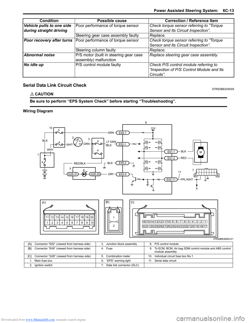
Serial Data Link Circuit CheckS7RS0B6304009
CAUTION!
Be sure to perform “EPS System Check” before starting “Troubleshooting”.
Wiring DiagramVehicle pulls to one side
during straight driving
Poor performance of torque sensor
Check torque sensor referring to “Torque
Sensor and Its Circuit Inspection”.
Steering gear case assembly faulty Replace.
Poor recovery after turns Poor performance of torque sensor Check torque sensor referring to “Torque
Sensor and Its Circuit Inspection”.
Steering column faulty Replace.
Abnormal noise P/S motor (built in steering gear case
assembly) malfunction Replace steering gear case assembly.
No idle up P/S control module faulty Check P/S control module referring to
“Inspection of P/S Control Module and Its
Circuits”.
Condition Possible cause Correction / Reference Item
MBLK
RED
E52-11 E51-1
E51-2PPL/WHT
[A ]
12
3
4 5 67
89
11
10
12 13
141516
17 18 19 2010 9 8 7654 3 21
16 15 14 13 12 11
26 25 24 2322 21 20 19 18 17
32 31 30 29 28 27
[C]
8
79
12V
[B ]
11
12
GRY
LT GRN
/BLK
E52-1
E52-5
E49-1
GRNGRNWHTBLK
WHY
G28-25G28-31
RED/BLK
10
3
4
4
5 6
4
4
1 2
4
E49-2BLK
I7RS0B630003-01
[A]: Connector “E52” (viewed from harness side) 3. Junction block assembly 8. P/S control module
[B]: Connector “E49” (viewed from harness side) 4. Fuse 9. T o ECM, BCM, Air bag SDM control module and ABS control
module assembly
[C]: Connector “G28” (viewed from harness side) 5. Comb ination meter 10. Individual circuit fuse box No.1
1. Main fuse box 6. “EPS” warning light 11. Serial data circuit
2. Ignition switch 7. Date link connector (DLC)
Page 911 of 1496

Downloaded from www.Manualslib.com manuals search engine Power Assisted Steering System: 6C-29
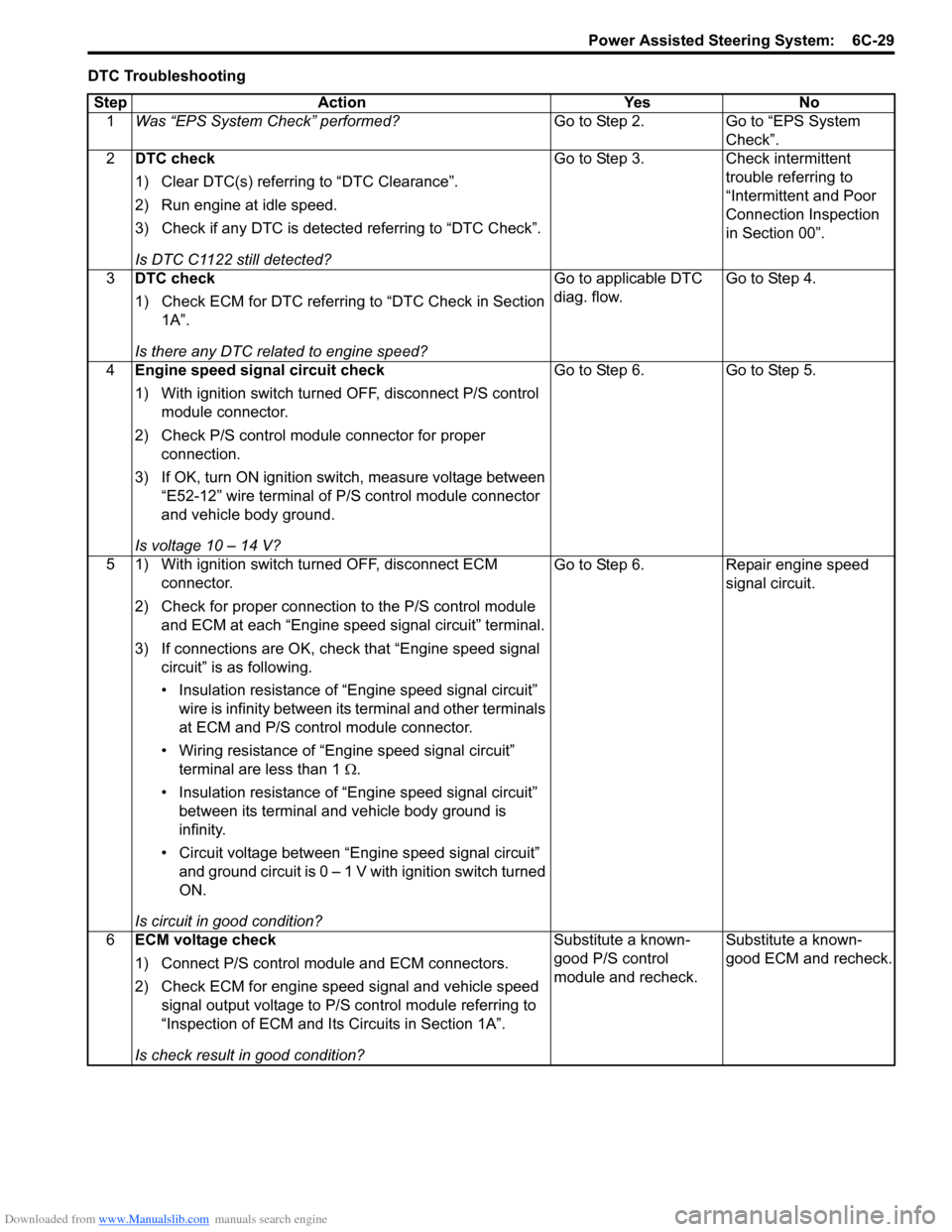
DTC TroubleshootingStep Action Yes No 1 Was “EPS System Check” performed? Go to Step 2. Go to “EPS System
Check”.
2 DTC check
1) Clear DTC(s) referring to “DTC Clearance”.
2) Run engine at idle speed.
3) Check if any DTC is detecte d referring to “DTC Check”.
Is DTC C1122 still detected? Go to Step 3. Check intermittent
trouble referring to
“Intermittent and Poor
Connection Inspection
in Section 00”.
3 DTC check
1) Check ECM for DTC referring to “DTC Check in Section
1A”.
Is there any DTC related to engine speed? Go to applicable DTC
diag. flow.
Go to Step 4.
4 Engine speed signal circuit check
1) With ignition switch turned OFF, disconnect P/S control
module connector.
2) Check P/S control module connector for proper connection.
3) If OK, turn ON ignition switch, measure voltage between “E52-12” wire terminal of P/S control module connector
and vehicle body ground.
Is voltage 10 – 14 V? Go to Step 6.
Go to Step 5.
5 1) With ignition switch turned OFF, disconnect ECM connector.
2) Check for proper connection to the P/S control module and ECM at each “Engine speed signal circuit” terminal.
3) If connections are OK, chec k that “Engine speed signal
circuit” is as following.
• Insulation resistance of “Engine speed signal circuit” wire is infinity between its terminal and other terminals
at ECM and P/S control module connector.
• Wiring resistance of “Engine speed signal circuit” terminal are less than 1 Ω.
• Insulation resistance of “Engine speed signal circuit” between its terminal and vehicle body ground is
infinity.
• Circuit voltage between “Engine speed signal circuit” and ground circuit is 0 – 1 V with ignition switch turned
ON.
Is circuit in good condition? Go to Step 6.
Repair engine speed
signal circuit.
6 ECM voltage check
1) Connect P/S control mo dule and ECM connectors.
2) Check ECM for engine speed signal and vehicle speed signal output voltage to P/S control module referring to
“Inspection of ECM and Its Circuits in Section 1A”.
Is check result in good condition? Substitute a known-
good P/S control
module and recheck.
Substitute a known-
good ECM and recheck.
Page 919 of 1496

Downloaded from www.Manualslib.com manuals search engine Power Assisted Steering System: 6C-37
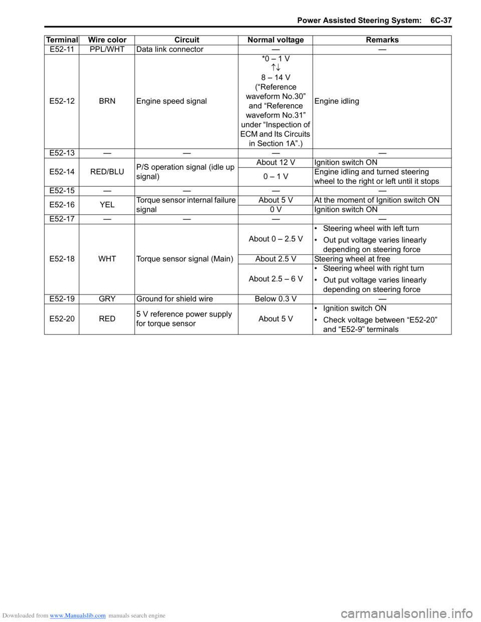
E52-11 PPL/WHT Data link connector——
E52-12 BRN Engine speed signal *0 – 1 V
↑↓
8 – 14 V
(“Reference
waveform No.30” and “Reference
waveform No.31”
under “Inspection of
ECM and Its Circuits in Section 1A”.) Engine idling
E52-13 — —— —
E52-14 RED/BLU P/S operation signal (idle up
signal) About 12 V Ignition switch ON
0 – 1 V Engine idling and turned steering
wheel to the right or left until it stops
E52-15 — —— —
E52-16 YEL Torque sensor internal failure
signal About 5 V At the moment of Ignition switch ON
0 V Ignition switch ON
E52-17 — —— —
E52-18 WHT Torque sensor signal (Main) About 0 – 2.5 V
• Steering wheel with left turn
• Out put voltage varies linearly
depending on steering force
About 2.5 V Steering wheel at free
About 2.5 – 6 V • Steering wheel with right turn
• Out put voltage varies linearly
depending on steering force
E52-19 GRY Ground for shield wire Below 0.3 V—
E52-20 RED 5 V reference power supply
for torque sensor About 5 V• Ignition switch ON
• Check voltage between “E52-20”
and “E52-9” terminals
Terminal Wire color
Circuit Normal voltage Remarks