Page 912 of 1496
Downloaded from www.Manualslib.com manuals search engine 6C-30 Power Assisted Steering System:
DTC C1141 / C1142 / C1143 / C1145: P/S Motor Circuit FailureS7RS0B6304019
DTC C1141: P/S Motor Circuit Voltage
DTC C1142: P/S Motor Circuit Range / Performance
DTC C1143: P/S Motor Circuit Current Too High
DTC C1145: P/S Motor Circuit Current Too Low
Wiring Diagram
MBLK
REDE51-1
E51-2
6
12V
5
[A ]
12 3
4 5 67
89
11
10
12 13
141516
17 18 19 20 8
8
12
[B ][C ]
12
LT GRN
/BLKE52-1 E49-1
GRNGRNWHTBLK
WHY
7
3
4
4
4
4
1 2
E49-2BLK
I7RS0B630010-01
[A]: Connector “E52” (viewed from harness side)
2. Ignition switch6. P/S motor
[B]: Connector “E49” (viewed from harness side) 3. Junction block assembly 7. Individual circuit fuse box No.1
[C]: Connector “E51” (viewed from harness side) 4. Fuse8. P/S motor circuit
1. Main fuse box 5. P/S control module
Page 914 of 1496

Downloaded from www.Manualslib.com manuals search engine 6C-32 Power Assisted Steering System:
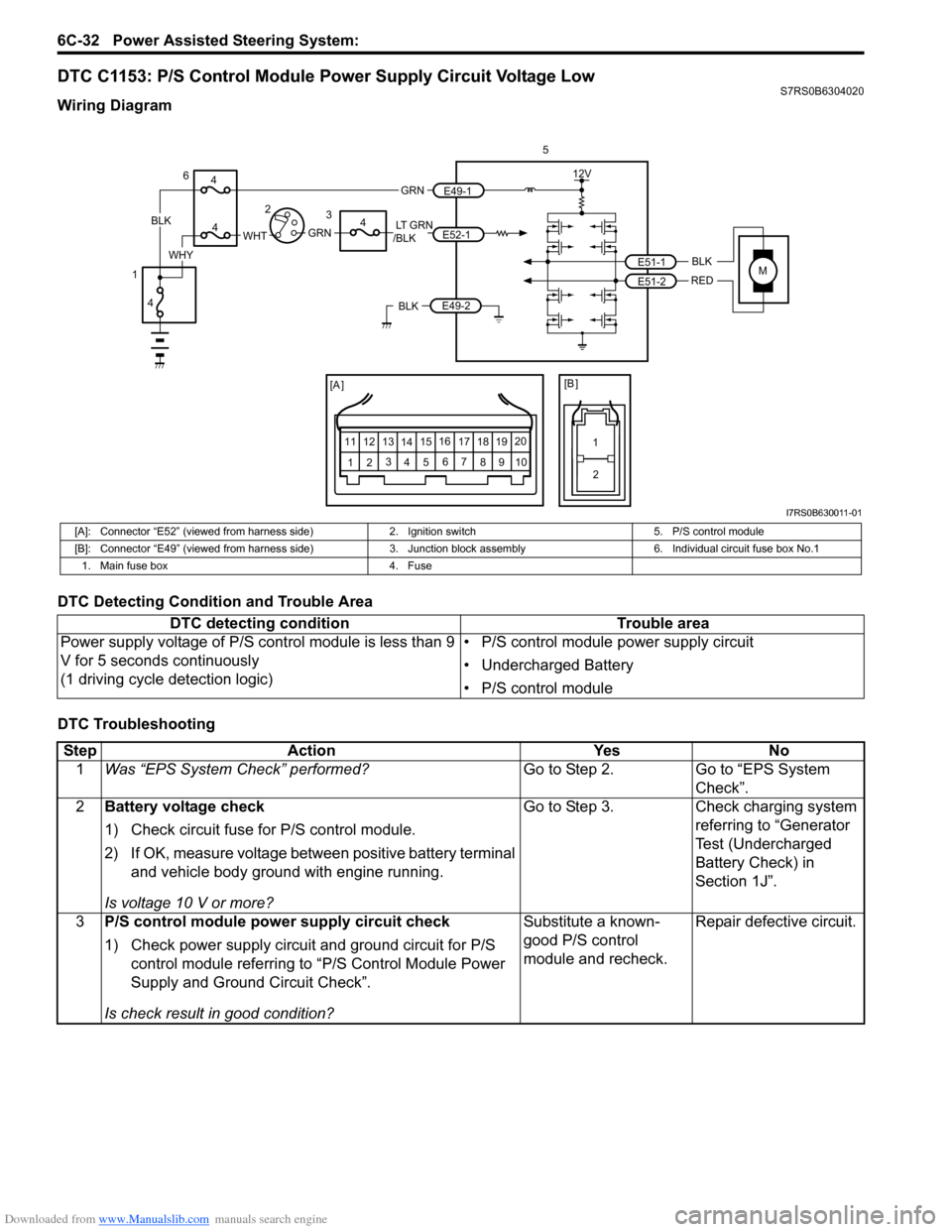
DTC C1153: P/S Control Module Power Supply Circuit Voltage LowS7RS0B6304020
Wiring Diagram
DTC Detecting Condition and Trouble Area
DTC Troubleshooting
MBLK
REDE51-1
E51-2
12V
5
[A ]
12 3
4 5 67
89
11
10
12 13
141516
17 18 19 20
[B ]
1
2
LT GRN
/BLKE52-1 E49-1
GRNGRNWHTBLK
WHY
6
3
4
4
4
4
1 2
E49-2BLK
I7RS0B630011-01
[A]: Connector “E52” (viewed from harness side)
2. Ignition switch5. P/S control module
[B]: Connector “E49” (viewed from harness side) 3. Junction block assembly 6. Individual circuit fuse box No.1
1. Main fuse box 4. Fuse
DTC detecting condition Trouble area
Power supply voltage of P/S control module is less than 9
V for 5 seconds continuously
(1 driving cycle detection logic) • P/S control module power supply circuit
• Undercharged Battery
• P/S control module
Step
Action YesNo
1 Was “EPS System Check” performed? Go to Step 2.Go to “EPS System
Check”.
2 Battery voltage check
1) Check circuit fuse for P/S control module.
2) If OK, measure voltage between positive battery terminal
and vehicle body ground with engine running.
Is voltage 10 V or more? Go to Step 3.
Check charging system
referring to “Generator
Test (Undercharged
Battery Check) in
Section 1J”.
3 P/S control module power supply circuit check
1) Check power supply circuit and ground circuit for P/S
control module referring to “P/S Control Module Power
Supply and Ground Circuit Check”.
Is check result in good condition? Substitute a known-
good P/S control
module and recheck.
Repair defective circuit.
Page 916 of 1496
![SUZUKI SWIFT 2008 2.G Service Workshop Manual Downloaded from www.Manualslib.com manuals search engine 6C-34 Power Assisted Steering System:
P/S Control Module Power Supply and Ground Circuit CheckS7RS0B6304022
Wiring Diagram
1
[A ]
123
4 5 67
8 SUZUKI SWIFT 2008 2.G Service Workshop Manual Downloaded from www.Manualslib.com manuals search engine 6C-34 Power Assisted Steering System:
P/S Control Module Power Supply and Ground Circuit CheckS7RS0B6304022
Wiring Diagram
1
[A ]
123
4 5 67
8](/manual-img/20/7607/w960_7607-915.png)
Downloaded from www.Manualslib.com manuals search engine 6C-34 Power Assisted Steering System:
P/S Control Module Power Supply and Ground Circuit CheckS7RS0B6304022
Wiring Diagram
1
[A ]
123
4 5 67
89
11
10
12 13
141516
17 18 19 20
[B ]
7
1
2
MBLK
REDE51-1
E51-2
12V
LT GRN
/BLKE52-1 E49-1
GRNGRNWHTBLK
WHY
3
3
5
6
1 2
E49-2BLK
I7RS0B630012-01
[A]: Connector “E52” (viewed from harness side)
2. Ignition switch5. “EPS” fuse
[B]: Connector “E49” (viewed from harness side) 3. Individual circuit fuse box No.1 6. “IG1 SIG” fuse
1. Main fuse box 4. Junction block assembly7. P/S control module
StepAction YesNo
1 Circuit fuse check
1) Disconnect P/S control modu le connector with ignition
switch turned OFF.
2) Check for proper connection to P/S control module connector at “E49-1”, “E49-2” and “E52-1” terminals.
3) If OK, check “P/S” fuse and “IG1 SIG” fuse for blowing.
Are “P/S” fuse and “IG1 SIG” fuse in good condition? Go to Step 2.
Replace fuse(s) and
check for short in
circuits connected to
fuse(s).
2 Power supply circuit check
1) Measure voltage between “E49-1” terminal of P/S
control module connector and body ground.
Is voltage 10 - 14 V? Go to Step 3.
“GRN” or “BLK” wire is
open circuit.
3 Ignition signal check
1) Turn ignition switch to ON position.
2) Measure voltage between “E52-1” terminal of P/S
control module connector and body ground.
Is voltage 10 - 14 V? Go to Step 4.
“LT GRN/BLK” or “GRN”
wire is open circuit.
4 P/S control module ground circuit check
1) Turn ignition switch to OFF position.
2) Disconnect connectors from P/S control module.
3) Measure resistance between “E49-2” terminals of P/S
control module connector and body ground.
Is resistance 1
Ω or less? Go to Step 5. “BLK” wire is open or
high resistance circuit.
Page 918 of 1496

Downloaded from www.Manualslib.com manuals search engine 6C-36 Power Assisted Steering System:
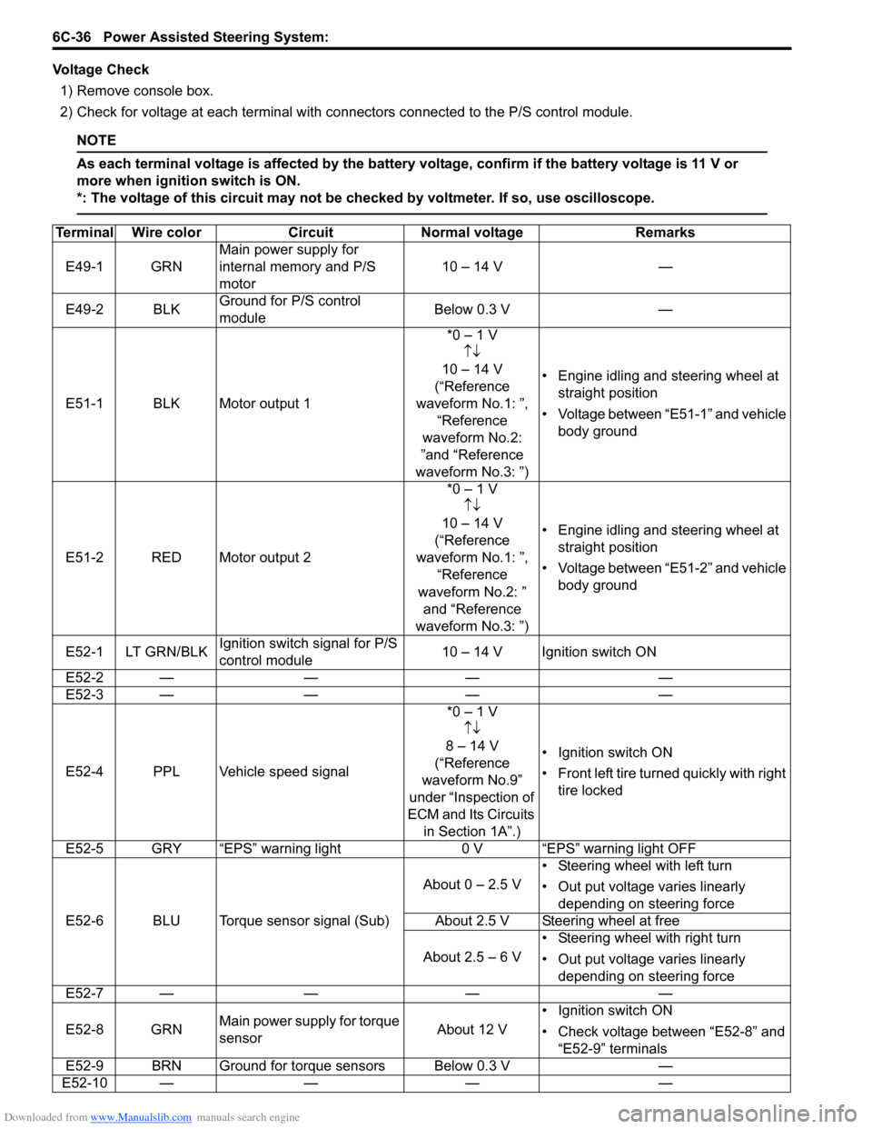
Voltage Check1) Remove console box.
2) Check for voltage at each terminal with co nnectors connected to the P/S control module.
NOTE
As each terminal voltage is affected by the battery voltage, confirm if the battery voltage is 11 V or
more when ignition switch is ON.
*: The voltage of this circuit may not be checked by voltmeter. If so, use oscilloscope.
Terminal Wire colorCircuit Normal voltage Remarks
E49-1 GRN Main power supply for
internal memory and P/S
motor 10 – 14 V
—
E49-2 BLK Ground for P/S control
module Below 0.3 V
—
E51-1 BLK Motor output 1 *0 – 1 V
↑↓
10 – 14 V
(“Reference
waveform No.1: ”, “Reference
waveform No.2:
”and “Reference
waveform No.3: ”) • Engine idling and steering wheel at
straight position
• Voltage between “E51-1” and vehicle body ground
E51-2 RED Motor output 2 *0 – 1 V
↑↓
10 – 14 V
(“Reference
waveform No.1: ”, “Reference
waveform No.2: ” and “Reference
waveform No.3: ”) • Engine idling and steering wheel at
straight position
• Voltage between “E51-2” and vehicle body ground
E52-1 LT GRN/BLK Ignition switch signal for P/S
control module 10 – 14 V Ignition switch ON
E52-2 — —— —
E52-3 — —— —
E52-4 PPL Vehicle speed signal *0 – 1 V
↑↓
8 – 14 V
(“Reference
waveform No.9”
under “Inspection of
ECM and Its Circuits in Section 1A”.) • Ignition switch ON
•Front left tire tu
rned quickly with right
tire locked
E52-5 GRY “EPS” warning light 0 V “EPS” warning light OFF
E52-6 BLU Torque sensor signal (Sub) About 0 – 2.5 V
• Steering wheel with left turn
• Out put voltage varies linearly
depending on steering force
About 2.5 V Steering wheel at free
About 2.5 – 6 V • Steering wheel with right turn
• Out put voltage varies linearly
depending on steering force
E52-7 — —— —
E52-8 GRN Main power supply for torque
sensor About 12 V• Ignition switch ON
• Check voltage between “E52-8” and
“E52-9” terminals
E52-9 BRN Ground for torque sensors Below 0.3 V —
E52-10 — —— —
Page 930 of 1496

Downloaded from www.Manualslib.com manuals search engine 6C-48 Power Assisted Steering System:
Specifications
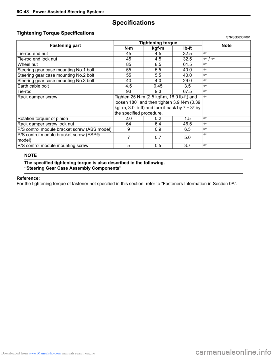
Tightening Torque SpecificationsS7RS0B6307001
NOTE
The specified tightening torque is also described in the following.
“Steering Gear Case Assembly Components”
Reference:
For the tightening torque of fastener not specified in this section, refer to “Fasteners Information in Section 0A”.
Fastening part
Tightening torque
Note
N ⋅mkgf-mlb-ft
Tie-rod end nut 454.5 32.5 �)
Tie-rod end lock nut 454.5 32.5 �) / �)
Wheel nut 858.5 61.5 �)
Steering gear case mounting No.1 bolt 555.5 40.0 �)
Steering gear case mounting No.2 bolt 555.5 40.0 �)
Steering gear case mounting No.3 bolt 404.0 29.0 �)
Earth cable bolt 4.5 0.45 3.5�)
Tie-rod 939.3 67.5 �)
Rack damper screw Tighten 25 N⋅m (2.5 kgf-m, 18.0 lb-ft) and
loosen 180 ° and then tighten 3.9 N ⋅m (0.39
kgf-m, 3.0 lb-ft) and turn it back by 7 ± 3° by
the specified procedure. �)
Rotation torquer of pinion 2.00.2 1.5 �)
Rack damper screw lock nut 646.4 46.5 �)
P/S control module bracket screw (ABS model) 9 0.9 6.5�)
P/S control module bracket screw (ESP ®
model) 70
.7 5 .0 �)
P/S control module mounting screw 50.5 3.7 �)
Page 938 of 1496
Downloaded from www.Manualslib.com manuals search engine 7A-2 Heater and Ventilation:
Schematic and Routing Diagram
Heater and Ventilation Wiring Circuit DiagramS7RS0B7102001
2. Ventilator duct 6. Foot air 10. Recirculation air 14. Resistance board
3. Defroster nozzle 7. Front defroster air 11. Center ventilation air 15. Rear duct (if equipped)
4. Heater core 8. Side defroster air 12. Air intake door
BLK
RED/BLK
3
5
7
BLK
2
M
12V
BLU/WHTE23-19
G18-3
G18-4
G18-7
G18-8
G18-10
G18-13
G19-2
G19-3
G19-7
G19-6
G19-1
G18-9
G18-14
BLK/WHT
YEL
BLU/WHT
RED
RED/BLK
RED
GRN
BRN
BLK/RED
RED/YEL
BLK
BLK/YEL
BLK/ORN
4
6
10
8
9
M1
12
11 13
14
15
I4RS0B710002-01
1. Ignition switch 5. Blower motor relay 9. ECM 13. Blower speed selector
2. Blower motor 6. Blower motor resistor 10. Air intake control actuator 14. Air intake selector
3. HVAC control unit 7. Junction block assembly 11. Ind ividual circuit fuse box No.1 15. Rear defogger switch
4. Lighting switch 8. BCM 12. Main fuse box
Page 942 of 1496

Downloaded from www.Manualslib.com manuals search engine 7A-6 Heater and Ventilation:
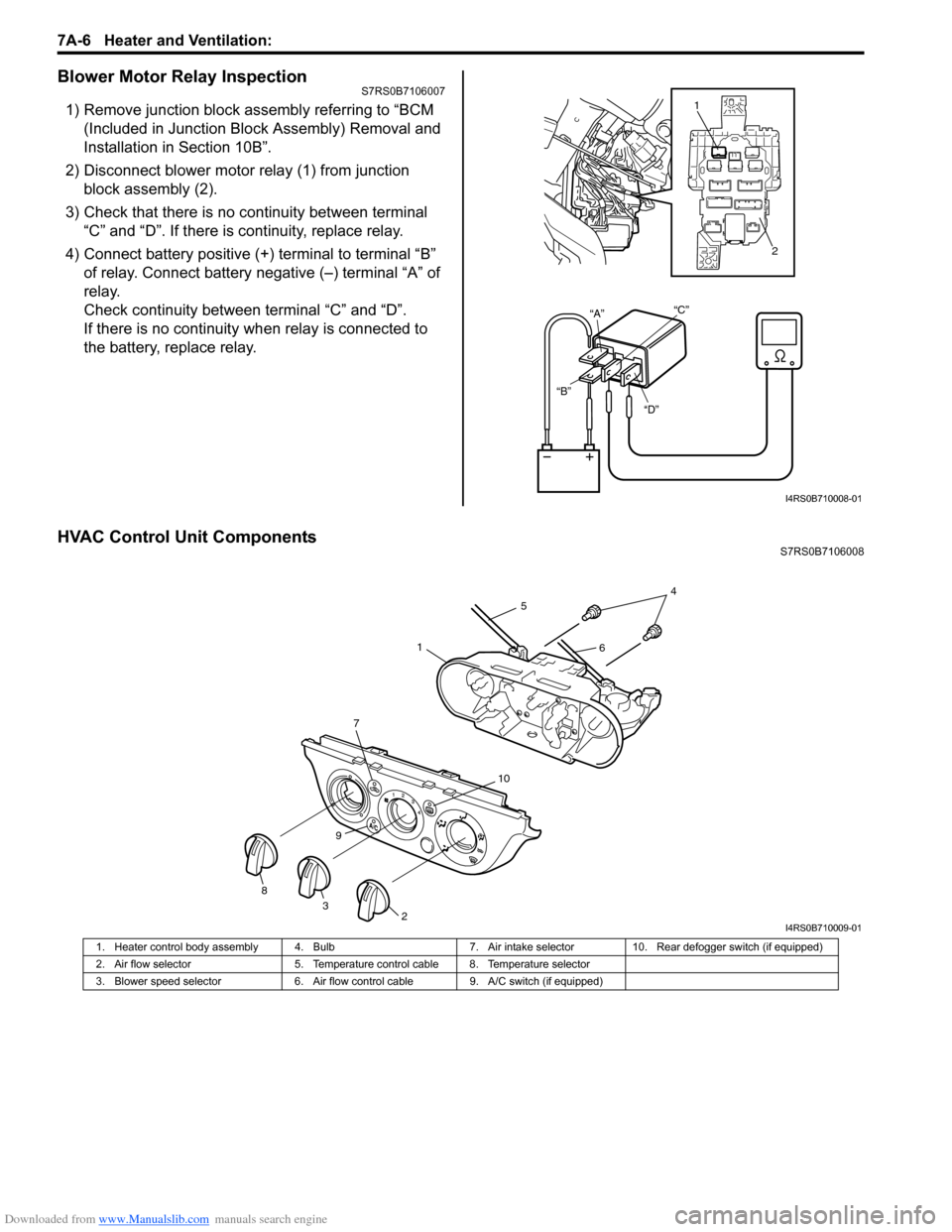
Blower Motor Relay InspectionS7RS0B7106007
1) Remove junction block assembly referring to “BCM (Included in Junction Block Assembly) Removal and
Installation in Section 10B”.
2) Disconnect blower motor relay (1) from junction block assembly (2).
3) Check that there is no continuity between terminal “C” and “D”. If there is continuity, replace relay.
4) Connect battery positive (+ ) terminal to terminal “B”
of relay. Connect battery negative (–) terminal “A” of
relay.
Check continuity between terminal “C” and “D”.
If there is no continuity wh en relay is connected to
the battery, replace relay.
HVAC Control Unit ComponentsS7RS0B7106008
“D”
“B” “A”
“C”
1
2
I4RS0B710008-01
45
61
7
10
9
238
I4RS0B710009-01
1. Heater control body assembly 4. Bulb 7. Air intake selector10. Rear defogger switch (if equipped)
2. Air flow selector 5. Temperature control cable 8. Temperature selector
3. Blower speed selector 6. Air flow control cable9. A/C switch (if equipped)
Page 944 of 1496
Downloaded from www.Manualslib.com manuals search engine 7A-8 Heater and Ventilation:
b. Move temperature control lever (1) and air flow control plate (2) fully to the arrow direction. c. Fix temperature control inner cable (1) to pin of
temperature control lever and air flow control inner
cable (2) to pin of air fl ow control plate, and then
fix each outer cable (3) to each cable lock clamp.
NOTE
After installing control cables, make sure that
control lever and plate move smoothly and
stop at proper position.
• Enable air bag system referring to “Enabling Air Bag System in Section 8B”.
• Make sure that air flow outlet changes correctly as air flow selector is changed.
[A]: LH steering vehicle [B]: RH steering vehicle
1
2
[A]
[B]
1
2
I4RS0B710014-01
[A]: LH steering vehicle [B]: RH steering vehicle
1
2
[B] [A] 3
3
1
3
23
I4RS0B710015-01