2008 SUZUKI SWIFT crank
[x] Cancel search: crankPage 672 of 1496
Downloaded from www.Manualslib.com manuals search engine 5A-28 Automatic Transmission/Transaxle:
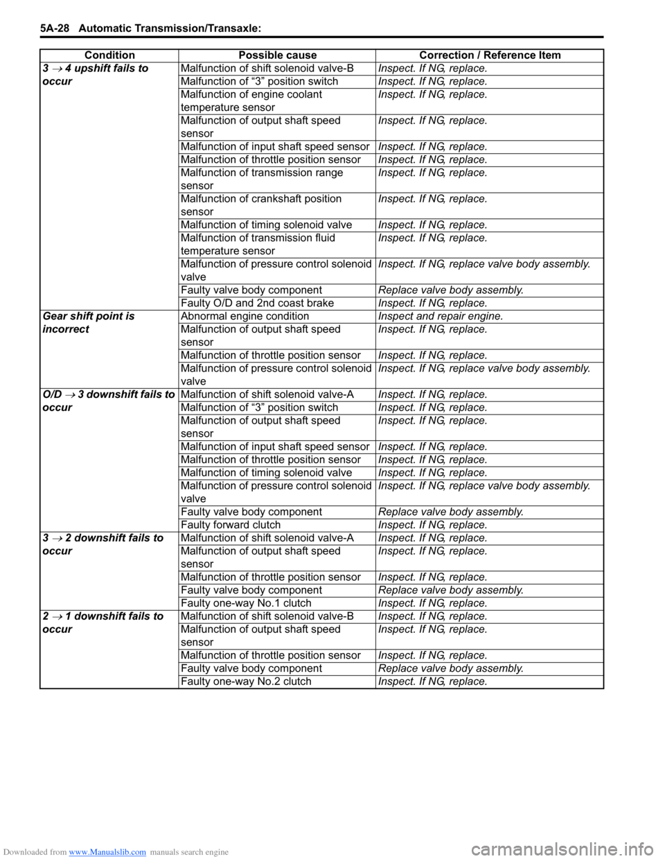
3 → 4 upshift fails to
occur Malfunction of shift solenoid valve-B
Inspect. If NG, replace.
Malfunction of “3” position switch Inspect. If NG, replace.
Malfunction of engine coolant
temperature sensor Inspect. If NG, replace.
Malfunction of output shaft speed
sensor Inspect. If NG, replace.
Malfunction of input shaft speed sensor Inspect. If NG, replace.
Malfunction of throttle position sensor Inspect. If NG, replace.
Malfunction of transmission range
sensor Inspect. If NG, replace.
Malfunction of crankshaft position
sensor Inspect. If NG, replace.
Malfunction of timing solenoid valve Inspect. If NG, replace.
Malfunction of transmission fluid
temperature sensor Inspect. If NG, replace.
Malfunction of pressure control solenoid
valve Inspect. If NG, replace valve body assembly.
Faulty valve body component Replace valve body assembly.
Faulty O/D and 2nd coast brake Inspect. If NG, replace.
Gear shift point is
incorrect Abnormal engine condition
Inspect and repair engine.
Malfunction of output shaft speed
sensor Inspect. If NG, replace.
Malfunction of throttle position sensor Inspect. If NG, replace.
Malfunction of pressure control solenoid
valve Inspect. If NG, replace valve body assembly.
O/D
→ 3 downshift fails to
occur Malfunction of shift solenoid valve-A
Inspect. If NG, replace.
Malfunction of “3” position switch Inspect. If NG, replace.
Malfunction of output shaft speed
sensor Inspect. If NG, replace.
Malfunction of input shaft speed sensor Inspect. If NG, replace.
Malfunction of throttle position sensor Inspect. If NG, replace.
Malfunction of timing solenoid valve Inspect. If NG, replace.
Malfunction of pressure control solenoid
valve Inspect. If NG, replace valve body assembly.
Faulty valve body component Replace valve body assembly.
Faulty forward clutch Inspect. If NG, replace.
3
→ 2 downshift fails to
occur Malfunction of shift solenoid valve-A
Inspect. If NG, replace.
Malfunction of output shaft speed
sensor Inspect. If NG, replace.
Malfunction of throttle position sensor Inspect. If NG, replace.
Faulty valve body component Replace valve body assembly.
Faulty one-way No.1 clutch Inspect. If NG, replace.
2
→ 1 downshift fails to
occur Malfunction of shift solenoid valve-B
Inspect. If NG, replace.
Malfunction of output shaft speed
sensor Inspect. If NG, replace.
Malfunction of throttle position sensor Inspect. If NG, replace.
Faulty valve body component Replace valve body assembly.
Faulty one-way No.2 clutch Inspect. If NG, replace.
Condition Possible cause Correction / Reference Item
Page 678 of 1496
Downloaded from www.Manualslib.com manuals search engine 5A-34 Automatic Transmission/Transaxle:
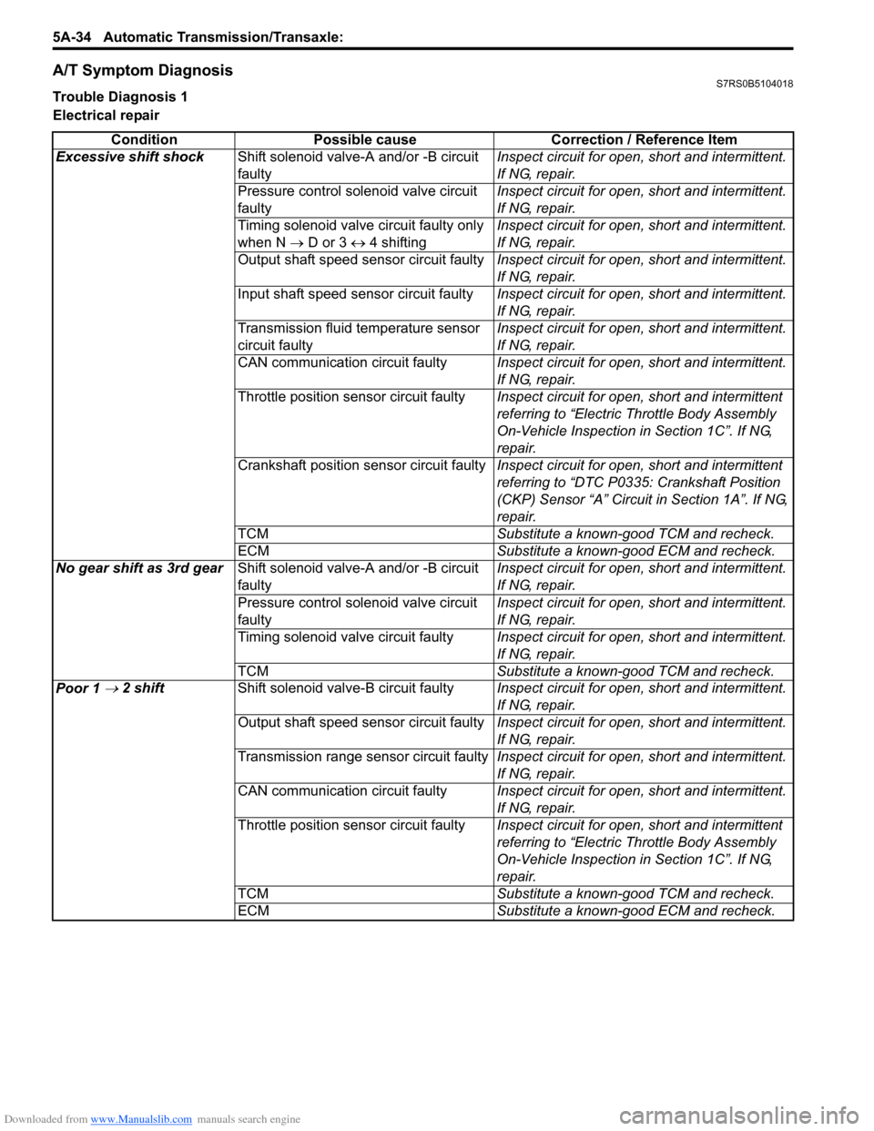
A/T Symptom DiagnosisS7RS0B5104018
Trouble Diagnosis 1
Electrical repair
Condition Possible cause Correction / Reference Item
Excessive shift shock Shift solenoid valve-A and/or -B circuit
faulty Inspect circuit for open, short and intermittent.
If NG, repair.
Pressure control solenoid valve circuit
faulty Inspect circuit for open, short and intermittent.
If NG, repair.
Timing solenoid valve circuit faulty only
when N → D or 3 ↔ 4 shifting Inspect circuit for open, short and intermittent.
If NG, repair.
Output shaft speed sensor circuit faulty Inspect circuit for open, short and intermittent.
If NG, repair.
Input shaft speed sensor circuit faulty Inspect circuit for open, short and intermittent.
If NG, repair.
Transmission fluid temperature sensor
circuit faulty Inspect circuit for open, short and intermittent.
If NG, repair.
CAN communication circuit faulty Inspect circuit for open, short and intermittent.
If NG, repair.
Throttle position sensor circuit faulty Inspect circuit for open, short and intermittent
referring to “Electric Throttle Body Assembly
On-Vehicle Inspection in Section 1C”. If NG,
repair.
Crankshaft position sensor circuit faulty Inspect circuit for open, short and intermittent
referring to “DTC P0335: Crankshaft Position
(CKP) Sensor “A” Circuit in Section 1A”. If NG,
repair.
TCM Substitute a known-good TCM and recheck.
ECM Substitute a known-good ECM and recheck.
No gear shift as 3rd gear Shift solenoid valve-A and/or -B circuit
faulty Inspect circuit for open, short and intermittent.
If NG, repair.
Pressure control solenoid valve circuit
faulty Inspect circuit for open, short and intermittent.
If NG, repair.
Timing solenoid valve circuit faulty Inspect circuit for open, short and intermittent.
If NG, repair.
TCM Substitute a known-good TCM and recheck.
Poor 1
→ 2 shift Shift solenoid valve-B circuit faulty Inspect circuit for open, short and intermittent.
If NG, repair.
Output shaft speed sensor circuit faulty Inspect circuit for open, short and intermittent.
If NG, repair.
Transmission range sensor circuit faulty Inspect circuit for open, short and intermittent.
If NG, repair.
CAN communication circuit faulty Inspect circuit for open, short and intermittent.
If NG, repair.
Throttle position sensor circuit faulty Inspect circuit for open, short and intermittent
referring to “Electric Throttle Body Assembly
On-Vehicle Inspection in Section 1C”. If NG,
repair.
TCM Substitute a known-good TCM and recheck.
ECM Substitute a known-good ECM and recheck.
Page 679 of 1496
Downloaded from www.Manualslib.com manuals search engine Automatic Transmission/Transaxle: 5A-35
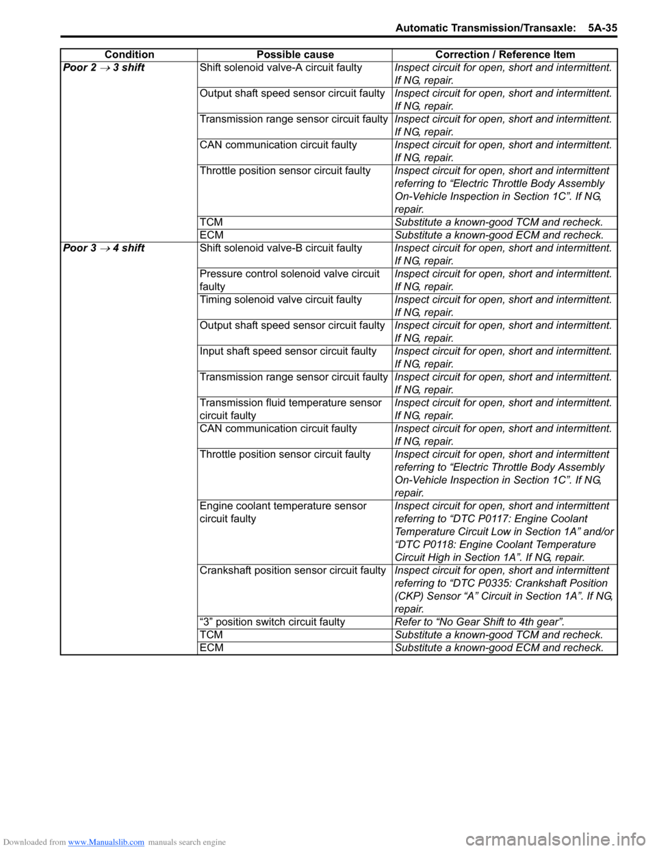
Poor 2 → 3 shiftShift solenoid valve-A circuit faulty Inspect circuit for open, short and intermittent.
If NG, repair.
Output shaft speed sensor circuit faulty Inspect circuit for open, short and intermittent.
If NG, repair.
Transmission range sensor circuit faulty Inspect circuit for open, short and intermittent.
If NG, repair.
CAN communication circuit faulty Inspect circuit for open, short and intermittent.
If NG, repair.
Throttle position sensor circuit faulty Inspect circuit for open, short and intermittent
referring to “Electric Throttle Body Assembly
On-Vehicle Inspection in Section 1C”. If NG,
repair.
TCM Substitute a known-good TCM and recheck.
ECM Substitute a known-good ECM and recheck.
Poor 3
→ 4 shift Shift solenoid valve-B circuit faulty Inspect circuit for open, short and intermittent.
If NG, repair.
Pressure control solenoid valve circuit
faulty Inspect circuit for open, short and intermittent.
If NG, repair.
Timing solenoid valve circuit faulty Inspect circuit for open, short and intermittent.
If NG, repair.
Output shaft speed sensor circuit faulty Inspect circuit for open, short and intermittent.
If NG, repair.
Input shaft speed sensor circuit faulty Inspect circuit for open, short and intermittent.
If NG, repair.
Transmission range sensor circuit faulty Inspect circuit for open, short and intermittent.
If NG, repair.
Transmission fluid temperature sensor
circuit faulty Inspect circuit for open, short and intermittent.
If NG, repair.
CAN communication circuit faulty Inspect circuit for open, short and intermittent.
If NG, repair.
Throttle position sensor circuit faulty Inspect circuit for open, short and intermittent
referring to “Electric Throttle Body Assembly
On-Vehicle Inspection in Section 1C”. If NG,
repair.
Engine coolant temperature sensor
circuit faulty Inspect circuit for open, short and intermittent
referring to “DTC P0117: Engine Coolant
Temperature Circuit Low
in Section 1A” and/or
“DTC P0118: Engine Coolant Temperature
Circuit High in Section 1A”. If NG, repair.
Crankshaft position sensor circuit faulty Inspect circuit for open, short and intermittent
referring to “DTC P0335: Crankshaft Position
(CKP) Sensor “A” Circuit in Section 1A”. If NG,
repair.
“3” position switch circuit faulty Refer to “No Gear Shift to 4th gear”.
TCM Substitute a known-good TCM and recheck.
ECM Substitute a known-good ECM and recheck.
Condition Possible cause Correction / Reference Item
Page 682 of 1496
Downloaded from www.Manualslib.com manuals search engine 5A-38 Automatic Transmission/Transaxle:
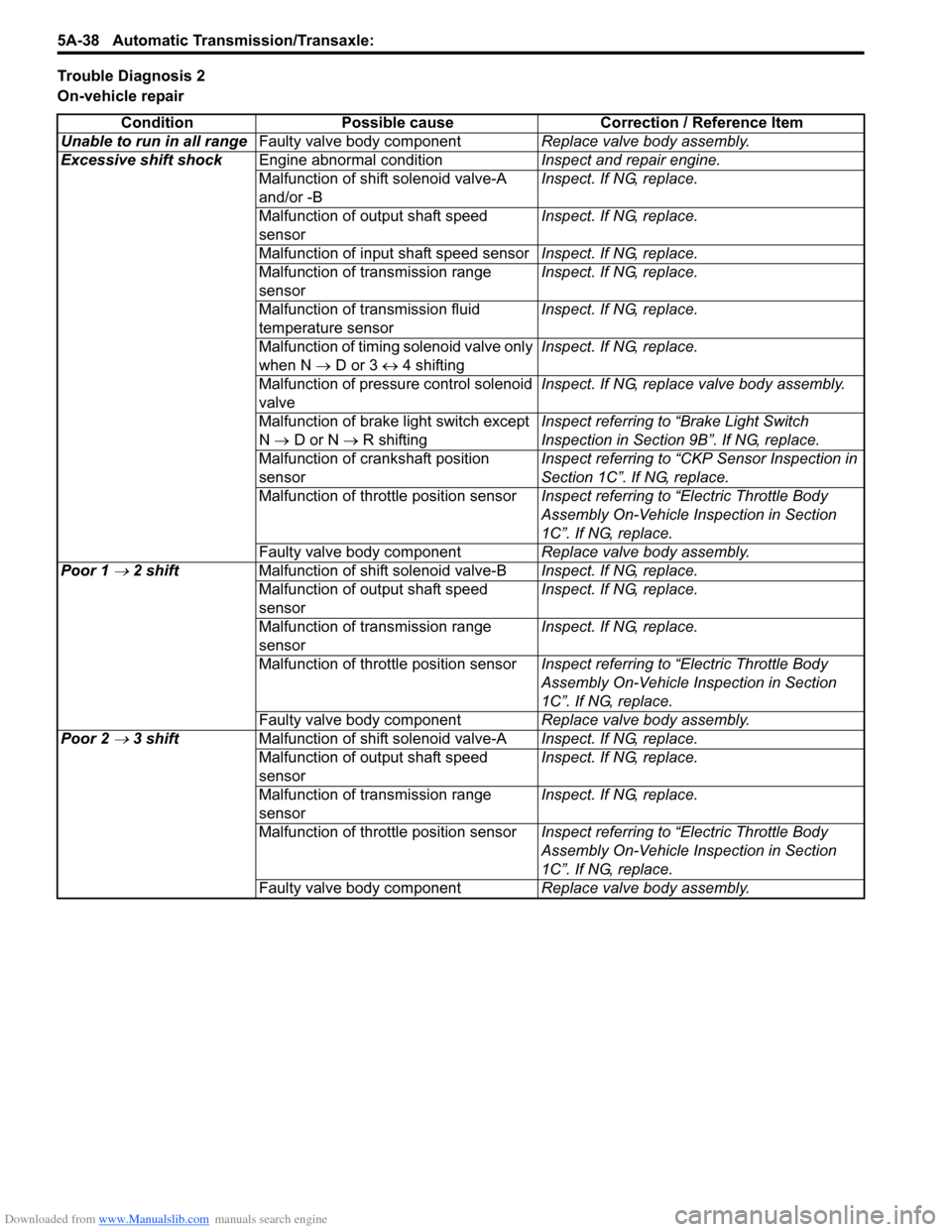
Trouble Diagnosis 2
On-vehicle repair
Condition Possible cause Correction / Reference Item
Unable to run in all range Faulty valve body component Replace valve body assembly.
Excessive shift shock Engine abnormal condition Inspect and repair engine.
Malfunction of shift solenoid valve-A
and/or -B Inspect. If NG, replace.
Malfunction of output shaft speed
sensor Inspect. If NG, replace.
Malfunction of input shaft speed sensor Inspect. If NG, replace.
Malfunction of transmission range
sensor Inspect. If NG, replace.
Malfunction of transmission fluid
temperature sensor Inspect. If NG, replace.
Malfunction of timing solenoid valve only
when N → D or 3 ↔ 4 shifting Inspect. If NG, replace.
Malfunction of pressure control solenoid
valve Inspect. If NG, replace valve body assembly.
Malfunction of brake light switch except
N → D or N → R shifting Inspect referring to “Brake Light Switch
Inspection in Section 9B”. If NG, replace.
Malfunction of crankshaft position
sensor Inspect referring to “CKP Sensor Inspection in
Section 1C”. If NG, replace.
Malfunction of throttle position sensor Inspect referring to “Electric Throttle Body
Assembly On-Vehicle Inspection in Section
1C”. If NG, replace.
Faulty valve body component Replace valve body assembly.
Poor 1
→ 2 shift Malfunction of shift solenoid valve-B Inspect. If NG, replace.
Malfunction of output shaft speed
sensor Inspect. If NG, replace.
Malfunction of transmission range
sensor Inspect. If NG, replace.
Malfunction of throttle position sensor Inspect referring to “Electric Throttle Body
Assembly On-Vehicle Inspection in Section
1C”. If NG, replace.
Faulty valve body component Replace valve body assembly.
Poor 2
→ 3 shift Malfunction of shift solenoid valve-A Inspect. If NG, replace.
Malfunction of output shaft speed
sensor Inspect. If NG, replace.
Malfunction of transmission range
sensor Inspect. If NG, replace.
Malfunction of throttle position sensor Inspect referring to “Electric Throttle Body
Assembly On-Vehicle Inspection in Section
1C”. If NG, replace.
Faulty valve body component Replace valve body assembly.
Page 750 of 1496
Downloaded from www.Manualslib.com manuals search engine 5A-106 Automatic Transmission/Transaxle:
Automatic Transaxle Unit Dismounting and
Remounting
S7RS0B5106031
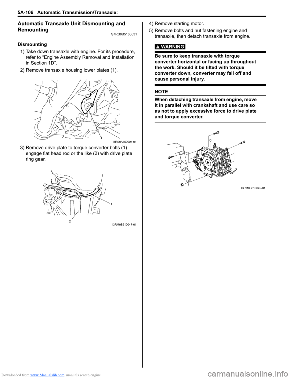
Dismounting1) Take down transaxle with engine. For its procedure, refer to “Engine Assembly Removal and Installation
in Section 1D”.
2) Remove transaxle housing lower plates (1).
3) Remove drive plate to torque converter bolts (1) engage flat head rod or the like (2) with drive plate
ring gear. 4) Remove starting motor.
5) Remove bolts and nut fastening engine and
transaxle, then detach transaxle from engine.WARNING!
Be sure to keep transaxle with torque
converter horizontal or facing up throughout
the work. Should it be tilted with torque
converter down, converter may fall off and
cause personal injury.
NOTE
When detaching transaxle from engine, move
it in parallel with cranks haft and use care so
as not to apply excessive force to drive plate
and torque converter.
1I4RS0A150004-01
I3RM0B510047-01
I3RM0B510049-01
Page 853 of 1496

Downloaded from www.Manualslib.com manuals search engine Clutch: 5C-1
Transmission / Transaxle
Clutch
General Description
Clutch ConstructionS7RS0B5301001
The clutch is a diaphragm spring clutch of a dry single disc type. The diaphragm spring is of a tapering-finger type,
which is a solid ring in the outer diameter part, with a series of tapered fingers pointing inward.
The disc, carrying four torsional coil springs, is positione d on the transaxle input shaft with an involute spline fit.
The clutch cover is secured to the flywheel, and carries the diaphragm spring in such a way that the peripheral edge
part of the spring pushes on the pressure plate against the flywheel (with the disc in between), when the clutch release
bearing is held back. This is the engaged condition of the clutch.
Depressing the clutch pedal c auses the release bearing to advance and pushes on the tips of the tapered fingers of
the diaphragm spring. When this happens, the diaphragm sp ring pulls the pressure plate away from the flywheel,
thereby interrupting the flow of drive from flywheel through clutch disc to transaxle input shaft. Clutch fluid is supplied
from brake fluid reservoir. Clutch fluid level can be checked by brake fluid level of brake fluid reservoir.
[A]: For petrol engine model2. Flywheel5. Clutch cover 8. Input shaft bearing
[B]: For diesel engine model 3. Clutch disc6. Diaphragm spring 9. Input shaft
1. Crankshaft 4. Pressure plate7. Release bearing 10. Release shaft
I4RS0A530001-01
Page 861 of 1496
Downloaded from www.Manualslib.com manuals search engine Clutch: 5C-9
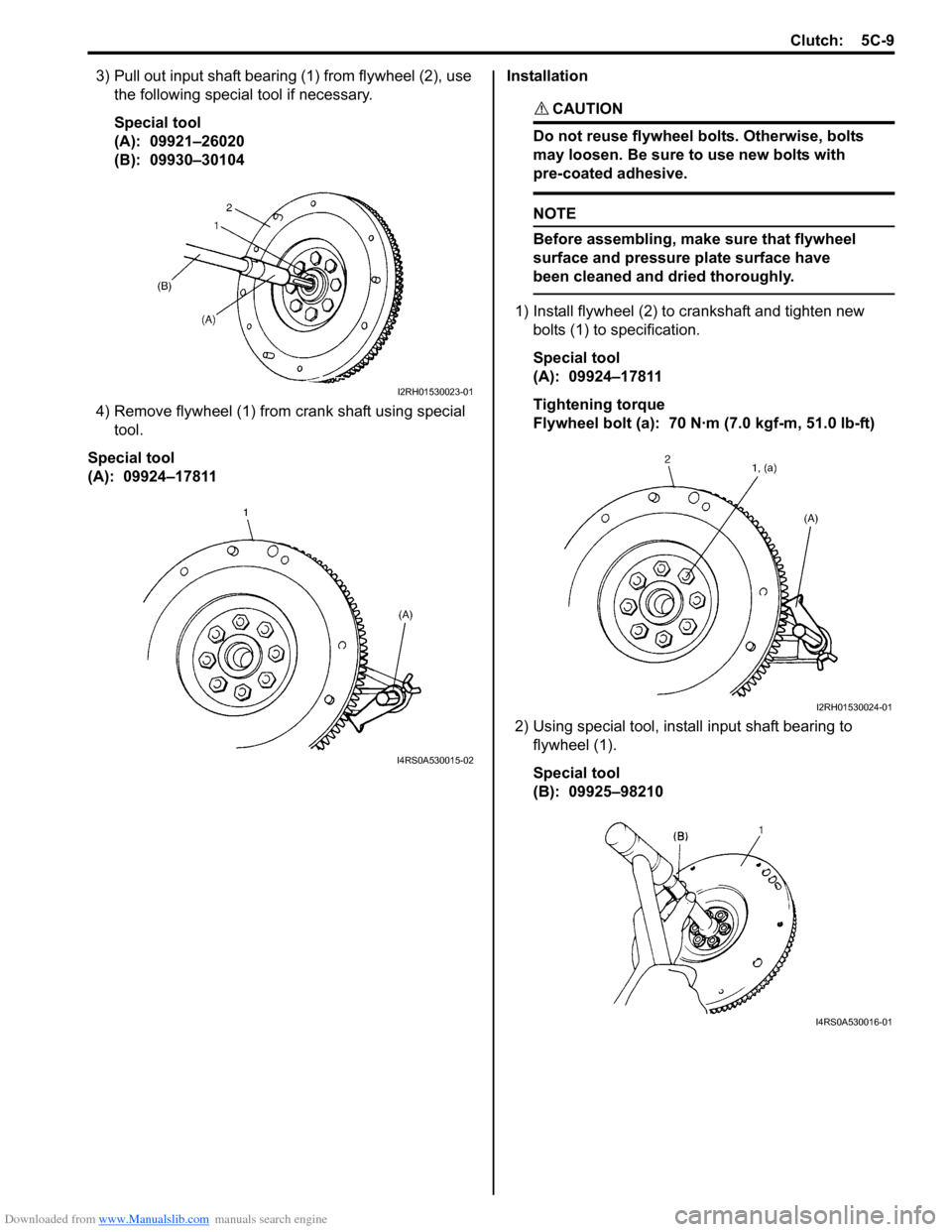
3) Pull out input shaft bearing (1) from flywheel (2), use the following special tool if necessary.
Special tool
(A): 09921–26020
(B): 09930–30104
4) Remove flywheel (1) from crank shaft using special tool.
Special tool
(A): 09924–17811 Installation
CAUTION!
Do not reuse flywheel bolts. Otherwise, bolts
may loosen. Be sure to use new bolts with
pre-coated adhesive.
NOTE
Before assembling, make
sure that flywheel
surface and pressure plate surface have
been cleaned and dried thoroughly.
1) Install flywheel (2) to crankshaft and tighten new bolts (1) to specification.
Special tool
(A): 09924–17811
Tightening torque
Flywheel bolt (a): 70 N·m (7.0 kgf-m, 51.0 lb-ft)
2) Using special tool, install input shaft bearing to flywheel (1).
Special tool
(B): 09925–98210
I2RH01530023-01
I4RS0A530015-02
I2RH01530024-01
I4RS0A530016-01
Page 862 of 1496

Downloaded from www.Manualslib.com manuals search engine 5C-10 Clutch:
3) Aligning clutch disc to flywheel center using special
tool, install clutch cover (1) and bolts (2). Then
tighten bolts (2) to specification.
NOTE
• While tightening clutch cover bolts, compress clutch disc with special tool
(clutch center guide) by hand so that disc
is centered.
• Tighten cover bolts little by little evenly in diagonal order.
Special tool
(A): 09924–17811
(B): 09923–36320
Tightening torque
Clutch cover bolt (a): 23 N·m (2.3 kgf-m, 17.0 lb-
ft)
4) Slightly apply grease to input shaft (1), then join manual transaxle assembly with engine referring to
“Manual Transaxle Unit Dismounting and
Remounting in Section 5B”.
“A”: Grease 99000–25210 (SUZUKI Super
Grease I)
NOTE
When inserting transaxle input shaft to clutch
disc, turn crankshaft li ttle by little to match
the splines.
Clutch Cover, Clutch Disc and Flywheel
Inspection
S7RS0B5306015
Input Shaft Bearing
Check bearing (1) for smooth ro tation and replace it if
abnormality is found.
Clutch Disc
Measure depth of rivet head depression, i.e. distance
between rivet head and facing surface.
If depression is found to hav e reached service limit at
any of rivet holes (2), repl ace clutch disc assembly (1).
Rivet head depth
Standard: 1.65 – 2.25 mm (0.06 – 0.09 in.)
Limit: 0.5 mm (0.02 in.)
I4RS0A530017-01
I4RS0A530018-01
I3RM0A530014-01
I4RS0A530019-01