2008 SUZUKI SWIFT meter connector
[x] Cancel search: meter connectorPage 1054 of 1496
Downloaded from www.Manualslib.com manuals search engine 8B-16 Air Bag System:
CAUTION!
• Be sure to perform “Air Bag Diagnostic System Check” before starting diagnosis according to flow.
• When measurement of resistance or voltage is required in this flow, use a tester along with a correct terminal adapter from special tool (Connector test adapter kit).
• When a check for proper connection is required, refer to “Inspection of Intermittent and Poor Connections”.
• If there is open circuit in the air bag wire harnes s, connector or terminal is found damaged, replace
the wire harness, connector and terminal as an assembly.
Flow Test Description
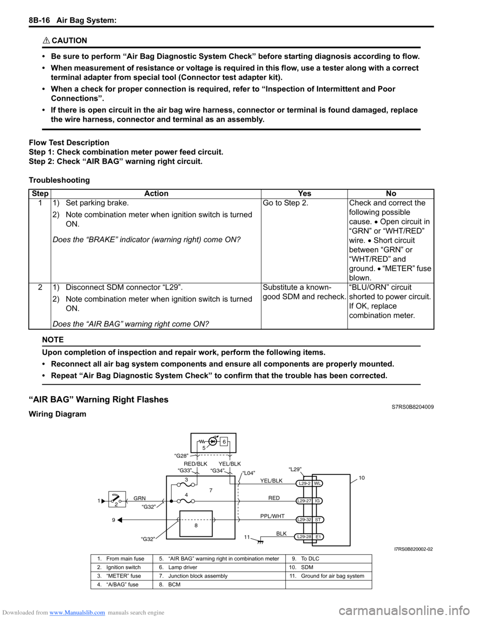
Step 1: Check combination meter power feed circuit.
Step 2: Check “AIR BAG” warning right circuit.
Troubleshooting
NOTE
Upon completion of inspection and repair work, perform the following items.
• Reconnect all air bag system components and ensure all components are properly mounted.
• Repeat “Air Bag Diagnostic System Check” to confirm that the trouble has been corrected.
“AIR BAG” Warning Right FlashesS7RS0B8204009
Wiring Diagram Step Action Yes No
1 1) Set parking brake.
2) Note combination me ter when ignition switch is turned
ON.
Does the “BRAKE” in dicator (warning right) come ON? Go to Step 2. Check and correct the
following possible
cause. • Open circuit in
“GRN” or “WHT/RED”
wire. • Short circuit
between “GRN” or
“WHT/RED” and
ground. • “METER” fuse
blown.
2 1) Disconnect SDM connector “L29”.
2) Note combination me ter when ignition switch is turned
ON.
Does the “AIR BAG” warning right come ON? Substitute a known-
good SDM and recheck.
“BLU/ORN” circuit
shorted to power circuit.
If OK, replace
combination meter.
1
2 GRN
11
BLK
L29-27
L29-2
L29-28 WL
E1
IG
L29-32
ST
10
8
“L29”
RED
PPL/WHT
7
3
4 “L04”
“G34”
“G33”
“G28”
“G32”
5 6
“G32”
YEL/BLK
YEL/BLK
RED/BLK
9
I7RS0B820002-02
1. From main fuse 5. “AIR BAG” warning right in combination meter 9. To DLC
2. Ignition switch 6. Lamp driver 10. SDM
3. “METER” fuse 7. Junction block assembly 11. Ground for air bag system
4. “A/BAG” fuse 8. BCM
Page 1055 of 1496
Downloaded from www.Manualslib.com manuals search engine Air Bag System: 8B-17
CAUTION!
• Be sure to perform “Air Bag Diagnostic System Check” before starting diagnosis according to flow.
• When measurement of resistance or voltage is required in this flow, use a tester along with a correct terminal adapter from special tool (Connector test adapter kit).
• When a check for proper connection is required, refer to “Inspection of Intermittent and Poor Connections”.
• If there is open circuit in the air bag wire harnes s, connector or terminal is found damaged, replace
the wire harness, connector and terminal as an assembly.
Flow Test Description
Check for short circuit between diag nosis switch circuit and ground.
Troubleshooting
NOTE
Upon completion of inspection and repair work, perform the following items.
• Reconnect all air bag system components and ensure all components are properly mounted.
• Repeat “Air Bag Diagnostic System Check” to confirm that the trouble has been corrected.
DTC B1013: SDM faultS7RS0B8204010
DTC Will Set when
An internal SDM fault is detected by SDM.
NOTE
DTC B1013 can never be cleared once it has been set.
DTC Troubleshooting 1) Turn ignition switch OFF.
2) Replace SDM.
3) Repeat “Air Bag Diagnostic System Check”.
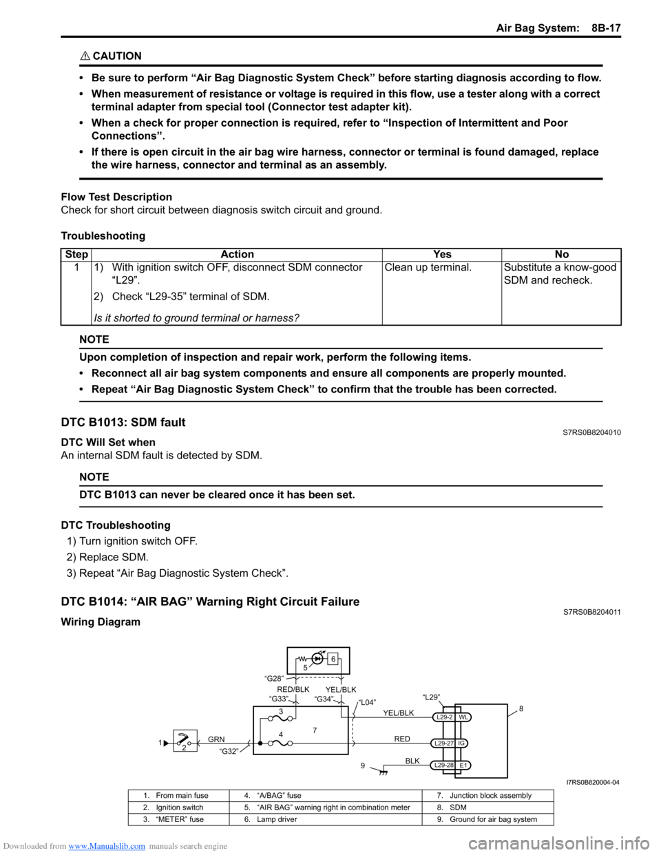
DTC B1014: “AIR BAG” Warning Right Circuit FailureS7RS0B8204011
Wiring DiagramStep Action Yes No
1 1) With ignition switch OFF, disconnect SDM connector “L29”.
2) Check “L29-35” terminal of SDM.
Is it shorted to ground terminal or harness? Clean up terminal. Substitute a know-good
SDM and recheck.
12 GRN
9
BLK
L29-2
L29-27
L29-28 IG
E1
WL
8
“L29”
RED
7
3
4 “L04”
“G34”
“G33”
“G28”
“G32”
5 6
YEL/BLK
YEL/BLK
RED/BLK
I7RS0B820004-04
1. From main fuse 4. “A/BAG” fuse
7. Junction block assembly
2. Ignition switch 5. “AIR BAG” warning right in combination meter 8. SDM
3. “METER” fuse 6. Lamp driver 9. Ground for air bag system
Page 1163 of 1496
Downloaded from www.Manualslib.com manuals search engine Air Bag System: 8B-125
Specifications
Tightening Torque SpecificationsS7RS0B8207001
NOTE
The specified tightening torque is also described in the following.
“Air Bag System Components, Wiring and Connectors Location”
Reference:
For the tightening torque of fastener not specified in this section, refer to “Fasteners Information in Section 0A”.
Special Tools and Equipment
Use of Special ToolsS7RS0B8208001
WARNING!
To avoid deployment when troubleshooting
the air bag system, do not use electrical test
equipment such as a battery powered or AC
powered voltmeter, ohmmeter, etc., or any
type of electrical equipment other than that
specified. Do not use a non-powered probe
type tester.
Instructions must be followed carefully,
otherwise personal injury may result.
You should be familiar with the tools listed under the
heading “Special Tool”. You should be able to measure
voltage and resistance. You should be familiar with
proper use of a scan tool such as Air Bag Driver /
Passenger Load Tool, Connector Test Adapter Kit and
the Digital Multimeter.
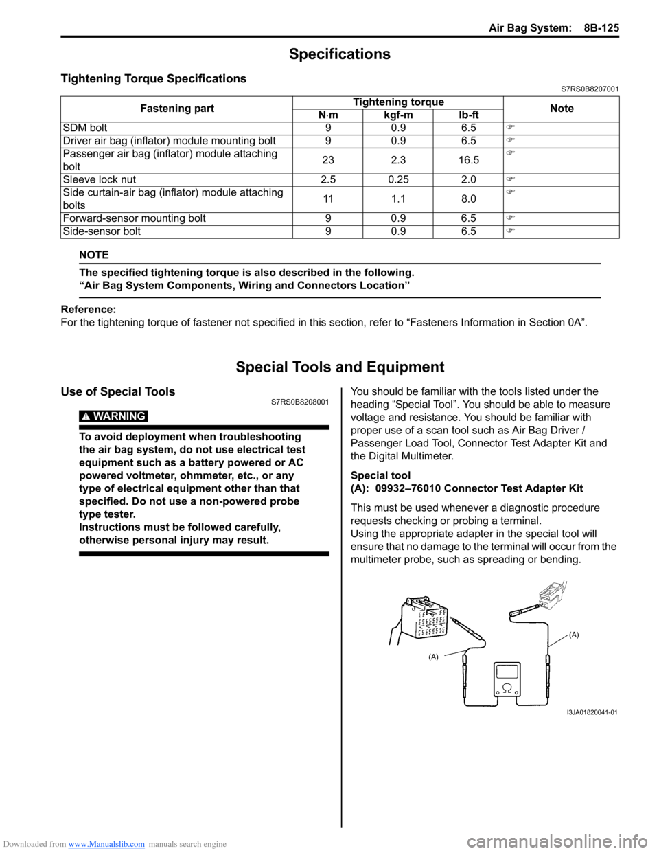
Special tool
(A): 09932–76010 Connector Test Adapter Kit
This must be used whenever a diagnostic procedure
requests checking or probing a terminal.
Using the appropriate adapter in the special tool will
ensure that no damage to the terminal will occur from the
multimeter probe, such as spreading or bending.
Fastening part
Tightening torque
Note
N ⋅mkgf-mlb-ft
SDM bolt 9 0.9 6.5 �)
Driver air bag (inflator) module mounting bolt 9 0.9 6.5 �)
Passenger air bag (inflator) module attaching
bolt 23 2.3 16.5�)
Sleeve lock nut 2.5 0.25 2.0 �)
Side curtain-air bag (inflator) module attaching
bolts 11 1.1 8.0�)
Forward-sensor mounting bolt 9 0.9 6.5 �)
Side-sensor bolt 9 0.9 6.5 �)
I3JA01820041-01
Page 1167 of 1496

Downloaded from www.Manualslib.com manuals search engine Table of Contents 9- i
9
Section 9
CONTENTS
Body, Cab and Accessories
Precautions ................................................. 9-1
Precautions............................................................. 9-1
Precautions on Body, Cab and Accessories ......... 9-1
Precautions for Body Service ................................ 9-1
Fastener Caution for Body Service ....................... 9-1
Wiring Systems............... ......................... 9A-1
Precautions........................................................... 9A-1
Cautions in Body Electrical System Servicing..... 9A-1
General Description ............................................. 9A-1 Abbreviations ...................................................... 9A-1
Wire / Connector Color Sy mbols ......................... 9A-1
Symbols and Marks ............................................ 9A-2
How to Read Connector Layout Diagram ........... 9A-4
How to Read Connector Codes and Terminal Nos.................................................................... 9A-5
How to Read Ground Point ................................. 9A-7
How to Read Power Supply Diagram.................. 9A-8
How to Read System Circuit Diagram................. 9A-8
Connector Layout Diagram . .............................. 9A-10
Connector Layout Diagram ............................... 9A-10
Engine Compartment .......... .............................. 9A-10
Instrument Panel ............................................... 9A-16
Door, Roof......................................................... 9A-20
Floor .................................................................. 9A-23
Rear .................................................................. 9A-29
Ground Point ...................................................... 9A-30 Ground (earth) Point ......................................... 9A-30
Power Supply Diagram ........ .............................. 9A-31
Power Supply Diagram ....... .............................. 9A-31
Fuses and the Protected Parts ......................... 9A-33
Fuses in Main Fuse Box (RHD) ........................ 9A-33
Fuses in Main Fuse Box (LHD) ......................... 9A-33
Individual Circuit Fuse Box No. 1 ...................... 9A-34
Individual Circuit Fuse Box No. 2 (In J/B) ......... 9A-35
Junction Block (J/B) Connector / Fuse Layout .. 9A-37
Junction Block Inner Circuit (Overview) ............ 9A-38
Junction Block Inner Circuit (Detail) .................. 9A-40
System Circuit Diagram... .................................. 9A-45
System Circuit Diagram .. .................................. 9A-45
A-1 Cranking System Circ uit Diagram .............. 9A-46
A-2 Charging System Circu it Diagram .............. 9A-47
A-3 Ignition System Circu it Diagram ................. 9A-48
A-4 Cooling System Circuit Diagram................. 9A-49 A-5 Engine and A/C Control System Circuit
Diagram........................................................... 9A-50
A-6 A/T Control System Circuit Diagram........... 9A-55
A-7 Immobilizer System Circuit Diagram .......... 9A-57
A-8 Body Control System Circuit Diagram ........ 9A-58
B-1 Windshield Wiper and Washer Circuit Diagram........................................................... 9A-62
B-2 Rear Wiper and Washer Circuit Diagram ... 9A-63
B-3 Rear Defogger Circuit Diagram .................. 9A-64
B-4 Power Window Circuit Diagram .................. 9A-65
B-5 Power Door Lock Circu it Diagram .............. 9A-67
B-6 Power Mirror Circuit Diagram ..................... 9A-69
B-7 Horn Circuit Diagram .................................. 9A-70
B-8 Seat Heater Circuit Diagram....................... 9A-71
B-9 Keyless Start System Circuit Diagram........ 9A-72
C-1 Combination Mete r Circuit Diagram
(Meter)............................................................. 9A-73
C-2 Combination Mete r Circuit Diagram
(Indicator) ........................................................ 9A-74
C-3 Combination Mete r Circuit Diagram
(Warning Light)................................................ 9A-75
D-1 Headlight System Circuit Diagram ............. 9A-77
D-2 Position, Tail and Licence Plate Light System Circuit Diagram .................................. 9A-79
D-3 Front Fog Light System Circuit Diagram .... 9A-80
D-4 Illumination Light System Circuit Diagram .. 9A-81
D-5 Interior Light System Circuit Diagram......... 9A-82
D-6 Turn Signal and Hazard Warning Light System Circuit Diagram .................................. 9A-83
D-7 Brake Light System Circuit Diagram .......... 9A-85
D-8 Back-Up Light System Circuit Diagram ...... 9A-86
D-9 Headlight Beam Leveling System Circuit Diagram........................................................... 9A-87
D-10 Rear Fog Light Circuit Diagram ................ 9A-88
E-1 Heater System Circuit Diagram .................. 9A-89
E-2 Auto A/C System Circuit Diagram .............. 9A-91
F-1 Air-Bag System Circuit Diagram ................. 9A-93
F-2 Anti-Lock Brake System Circuit Diagram.... 9A-95
F-3 Electronic Stab ility Program System
Circuit Diagram .................. ............................. 9A-97
F-4 Power Steering System Circuit Diagram .... 9A-99
G-1 Audio System Circuit Diagram ................. 9A-101
G-2 Multi Information Display / Accessory Socket System Circuit Diagram .................... 9A-102
List of Connector .............................................9A-103
Page 1168 of 1496

Downloaded from www.Manualslib.com manuals search engine 9-ii Table of Contents
List of Connectors ........................................... 9A-103
C Connector .................................................... 9A-103
D Connector (M16A engine) ........................... 9A-104
E Connector .................................................... 9A-104
G Connector .................................................... 9A-106
J Connector ..................................................... 9A-108
K Connector .................................................... 9A-109
L Connector..................................................... 9A-109
M Connector (SPORT model) ......................... 9A-111
O Connector .................................................... 9A-111
R Connector .................................................... 9A-111
Lighting Systems .................................... 9B-1
Component Location ........... ................................9B-1
Lighting System Component s Location............... 9B-1
Interior Light System Location............................. 9B-2
Diagnostic Information and Procedures ............ 9B-2 Headlight Symptom Diagnosis ............................ 9B-2
Headlight Leveling System Symptom Diagnosis (If Equipped) ..................................... 9B-2
Turn Signal and Hazard Warning Light Symptom Diagnosis .......................................... 9B-3
Clearance, Tail and License Plate Light Symptom Diagnosis .......................................... 9B-3
Back-Up Light Symptom Diagnosis..................... 9B-4
Brake Light Symptom Diagnosis ......................... 9B-4
Front Fog Light Symptom Diagnosis (If Equipped) .......................................................... 9B-4
Interior Light Symptom Diagnosis ....................... 9B-5
Repair Instructions ..............................................9B-5 Headlight Housing Removal and Installation ...... 9B-5
Headlight Bulb Replacemen t............................... 9B-6
Headlight Aiming Adjustment with Screen .......... 9B-6
Headlight Switch (in Lighting Switch) Removal and Installation ................................... 9B-8
Headlight Switch (in Lighting Switch) Inspection .......................................................... 9B-8
Hazard Warning Switch Removal and Installation ......................................................... 9B-8
Hazard Warning Switch Inspection ..................... 9B-9
Brake Light Switch Inspection ............................. 9B-9
Turn Signal Light Switch (in Lighting Switch) Removal and Installation ................................... 9B-9
Turn Signal Light Switch (in Lighting Switch) Inspection .......................................................... 9B-9
Turn Signal and Hazard Warning Relay Removal and Installation ................................... 9B-9
Turn Signal and Hazard Warning Relay Inspection ........................................................ 9B-10
License Light Removal and Installation............. 9B-10
Front Fog Light Removal and Installation (If Equipped) ........................................................ 9B-11
Front Fog Light Bulb Replacement (If Equipped) ........................................................ 9B-11
Front Fog Light Switch Inspection (If Equipped) ........................................................ 9B-11
Front Fog Light Relay Inspection (If Equipped) ........................................................ 9B-11
Front Fog Light Aiming Adjustment with Screen (If Equipped) ....................................... 9B-12 Headlight Leveling Switch Inspection (If
Equipped) ........................................................ 9B-13
Headlight Leveling Actuator Inspection (If Equipped) ........................................................ 9B-13
Instrumentation / Driver Info. / Horn ...... 9C-1
Precautions ...........................................................9C-1 Precautions in Diagnosing Troubles for Combination Meter ............................................9C-1
General Description .............................................9C-1 CAN Communication System Description...........9C-1
Auto Volume Co ntrol System Description (If
Equipped) ..........................................................9C-3
Schematic and Routing Diagram ........................9C-4 Combination Meter Circuit Diagram ....................9C-4
Component Location ............ ...............................9C-6
Audio System Component Location ....................9C-6
Diagnostic Information and Procedures ............9C-6 Speedometer and VSS Symp tom Diagnosis ......9C-6
Tachometer Symptom Diagnosis ........................9C-6
Engine Coolant Temperature (ECT) Meter Symptom Diagnosis ..........................................9C-7
Fuel Meter Symptom Diagnosis ..........................9C-7
Low Fuel Warning Light Symptom Diagnosis .....9C-7
Oil Pressure Warning Light Symptom Diagnosis ..........................................................9C-8
Brake and Parking Brake Warning Light Symptom Diagnosis ..........................................9C-8
Seat Belt Reminder Light Symptom Diagnosis (If Equipped)......................................................9C-8
A/T Shift Position Indicator Symptom Diagnosis (A/T Model).......................................9C-9
Charge Warning Light Sy mptom Diagnosis ........9C-9
Main Beam (High Beam) Indicator Symptom Diagnosis ..........................................................9C-9
Warning Buzzer Circuit Sy mptom Diagnosis ....9C-10
Cigarette Lighter Symptom Diagnosis (If Equipped) ........................................................9C-10
Horn Symptom Diagnosis .................................9C-10
Information Display Symptom Diagnosis (If Equipped) ........................................................9C-11
Clock Symptom Diagnosis (If Equipped)...........9C-12
Audio System Symptom Diagnosis (If Equipped) ........................................................9C-12
Remote Audio Control Switch Symptom Diagnosis (If Equipped) ...................................9C-13
Navigation Symptom Diagnosis (If Equipped)...9C-14
Repair Instructions ............ ................................9C-14
Ignition Switch Removal and Installation...........9C-14
Ignition Switch Inspection..................................9C-14
Combination Meter Removal and Installation ...9C-15
Fuel Level Sensor Removal and Installation .....9C-15
Fuel Level Sensor Inspection ............................9C-15
Oil Pressure Switch Remova l and Installation ..9C-15
Oil Pressure Switch Inspec tion .........................9C-16
Engine Coolant Temperature (ECT) Sensor Inspection ........................................................9C-16
Brake Fluid Level Switch Inspection .................9C-16
Parking Brake Switch Inspec tion.......................9C-16
Page 1211 of 1496
Downloaded from www.Manualslib.com manuals search engine Wiring Systems: 9A-40
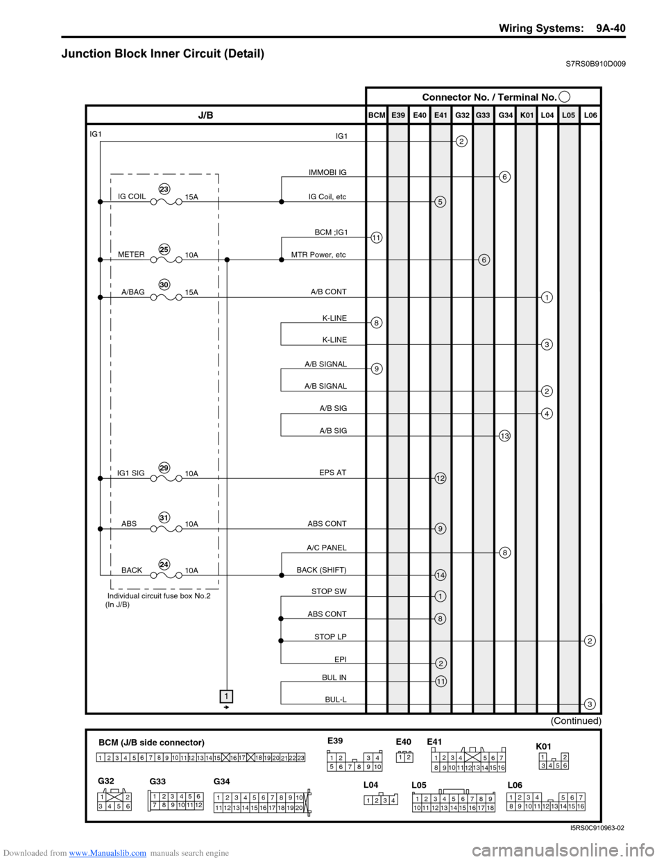
Junction Block Inner Circuit (Detail)S7RS0B910D009
BCM (J/B side connector)
34
1
2 5
15
14
12
13
10
11
9
8
6
7
17
161821 22
19
20
23
1234578 11 6
12
91034 6 52
1
G33
G32
G34
10
11 12 13 14 15 16 17 18 19 123456789
20
345612K01
23414
3
561214
11
10 157
2113 16
98
6
5
4
3
2
1
7
11
10
9
8
15
14
13
12 16
L04
L06
E41
21
123456789
15 16 17 18
1110 12 13 14
1
234
5 678 910
E39
L05
E40
IMMOBI IG
IG1
IG Coil, etc E39 E41E40
BCM G34G33G32 K01 L04 L05 L06
IG COIL
IG1
15A
METER10A
A/BAG15A
2
6
5
13
J/B Connector No. / Terminal No.
BCM ;IG1
MTR Power, etc
A/B CONT
K-LINE K-LINE
A/B SIGNAL
A/B SIGNAL
A/B SIG
A/B SIG
IG1 SIG 10AEPS AT
ABS CONT
STOP SW
ABS CONT
STOP LP EPI
BUL IN
BUL-L
BACK (SHIFT)
A/C PANEL
6
1
3
2
4
8
11
9
12
9
14
1
2
3
8
2
11
8
ABS
10A
BACK10A
1
(Continued)
Individual circuit fuse box No.2
(In J/B)
23
25
30
29
31
24
I5RS0C910963-02
Page 1212 of 1496
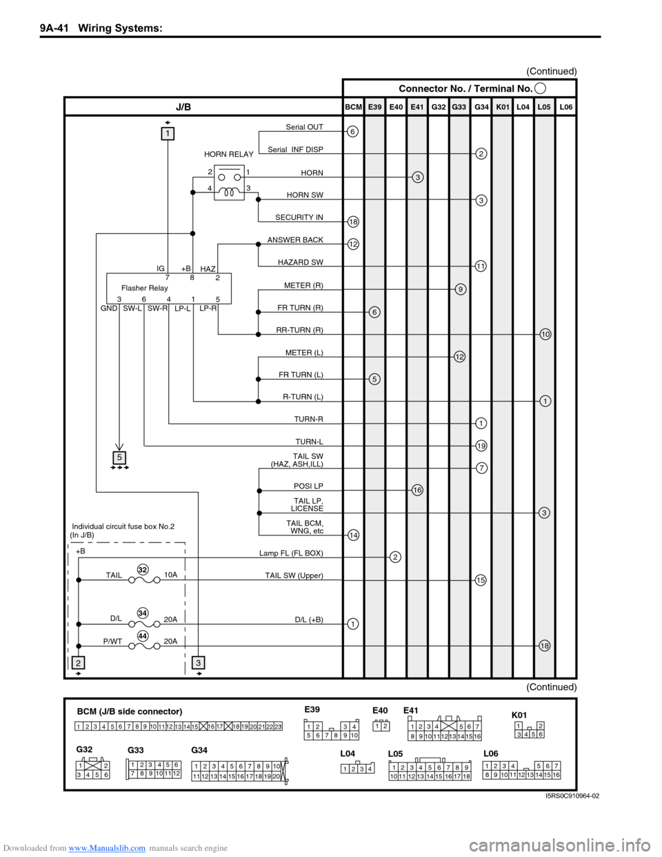
Downloaded from www.Manualslib.com manuals search engine 9A-41 Wiring Systems:
BCM (J/B side connector)
34
1
2 5
15
14
12
13
10
11
9
8
6
7
17
161821 22
19
20
23
1234578 11 6
12
91034 6 52
1
G33
G32
G34
10
11 12 13 14 15 16 17 18 19 123456789
20
345612K01
23414
3
561214
11
10 157
2113 16
98
6
5
4
3
2
1
7
11
10
9
8
15
14
13
12 16
L04
L06
E41
21
12 34 5 6 78 9
15 16 17 18
1110 12 13 14
1
234
5 678 910
E39
L05
E40
E39 E41E40
BCM G34G33G32K01 L04 L05 L06
11
J/B
Flasher Relay 78
2
5
1463
6
12
3
6
9
3
12
1
5
1
19
14
3
18
7
16
2
15
1
10
1Serial OUT
Serial INF DISP
HORN SW
HORN RELAY
GND SW-L SW-R
LP-LLP-R
IG
+B
HAZ HORN
SECURITY IN
ANSWER BACK HAZARD SW
METER (R)
FR TURN (R)
METER (L)
RR-TURN (R)
FR TURN (L) R-TURN (L)
TURN-R
TAIL SW
(HAZ, ASH,ILL) TURN-L
POSI LP TAIL LP,
LICENSE
TAIL BCM, WNG, etc
Lamp FL (FL BOX)
TAIL SW (Upper)
TAIL 10A
+B
D/L 20A
P/WT 20A D/L (+B)
32
(Continued)
Individual circuit fuse box No.2
(In J/B)
32
34
44
(Continued)
1
2
3
4
5
Connector No. / Terminal No.
2
18
I5RS0C910964-02
Page 1232 of 1496
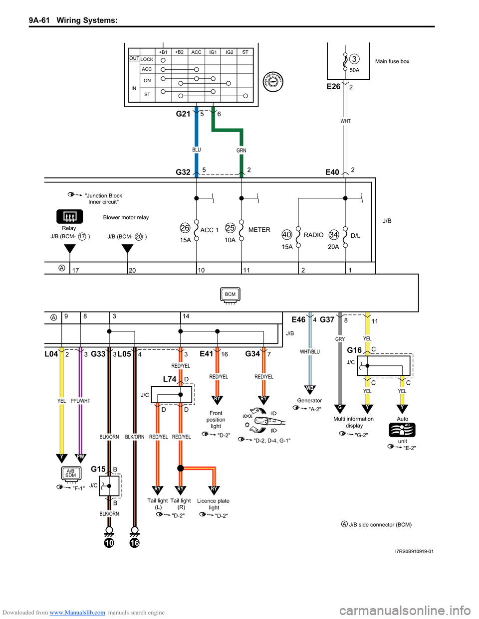
Downloaded from www.Manualslib.com manuals search engine 9A-61 Wiring Systems:
50A
3
J/B
15ARADIO
40
2
15A
ACC 1
26
10
1
20AD/L
34
11
10A
METER
25
Main fuse box
WHT
E402
20
Blower motor relay
"Junction Block Inner circuit"
Relay
J/B (BCM- 20 )J/B (BCM- 17 )
17
2L04
9
3
83
B BG33
3
4L05
10
J/C
G15
BLK/ORN
BLK/ORN
16
BLK/ORN
"F-1"
YELPPL/WHT
A/B
SDM
14
316E417G34
Front
position light
"D-2"
"D-2, D-4, G-1"
J/B
RED/YELRED/YEL
J/C
L74D
DD
Licence plate light
"D-2"
YPW
"A-2"
Generator
E464
WHT/BLU
WB
RYRY
RYRYRY
Tail light
(R)
Tail light
(L)
"D-2"
RED/YEL
RED/YEL
RED/YEL
811
C CG37
J/C
G16
YEL
GRYYEL
GY
C
YEL
Y
"G-2"
Multi information
display Auto
unit
"E-2"
A
A
J/C
2E26
+B1
LOCK
ACC
ON
ST ACC IG1 IG2
STOUT
IN
+B2
BLUGRN
G3252
56G21
J/B side connector (BCM)
A
BCM
I7RS0B910919-01