Page 1172 of 1496

Downloaded from www.Manualslib.com manuals search engine 9A-1 Wiring Systems:
Body, Cab and Accessories
Wiring Systems
Precautions
Cautions in Body Electrical System ServicingS7RS0B9100001
When servicing the electric systems, observe the cautions described in “Precautions for Electrical Circuit Service in
Section 00” to protect electrical parts and to prevent a fire.
General Description
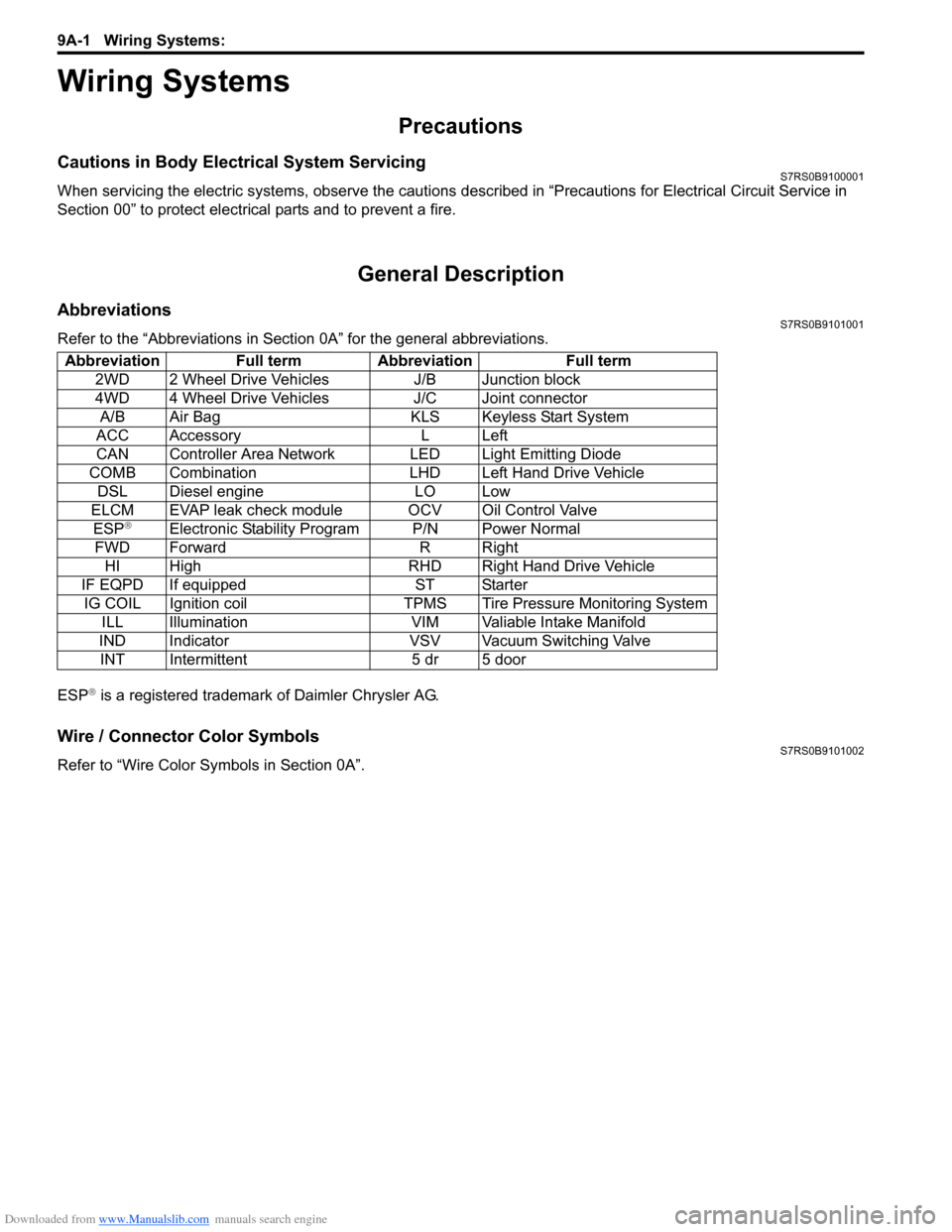
AbbreviationsS7RS0B9101001
Refer to the “Abbreviations in Sect ion 0A” for the general abbreviations.
ESP
® is a registered trademark of Daimler Chrysler AG.
Wire / Connector Color SymbolsS7RS0B9101002
Refer to “Wire Color Sy mbols in Section 0A”.
Abbreviation Full term Abbreviation Full term
2WD 2 Wheel Drive Vehicles J/B Junction block
4WD 4 Wheel Drive Vehicles J/C Joint connectorA/B Air Bag KLS Keyless Start System
ACC Accessory L Left
CAN Controller Area Network LED Light Emitting Diode
COMB Combination LHD Left Hand Drive Vehicle DSL Diesel engine LO Low
ELCM EVAP leak check module OCV Oil Control Valve ESP
®Electronic Stability Program P/N Power Normal
FWD Forward R Right HI High RHD Right Hand Drive Vehicle
IF EQPD If equipped ST Starter IG COIL Ignition coil TPMS Tire Pressure Monitoring System ILL Illumination VIM Valiable Intake Manifold
IND Indicator VSV Vacuum Switching Valve INT Intermittent 5 dr 5 door
Page 1177 of 1496

Downloaded from www.Manualslib.com manuals search engine Wiring Systems: 9A-6
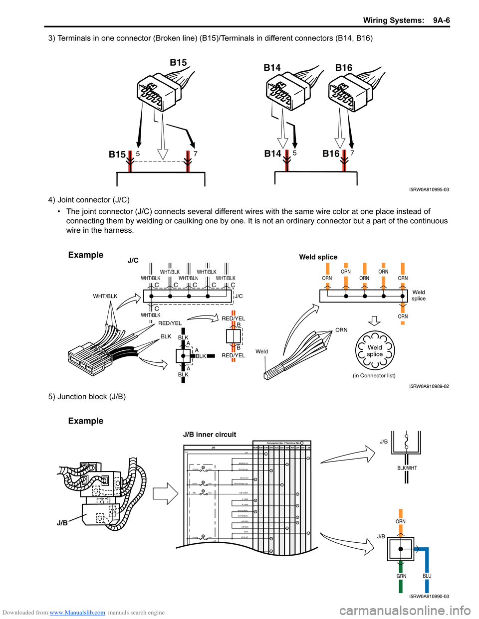
3) Terminals in one connector (Broken line) (B15)/Terminals in different connectors (B14, B16)
4) Joint connector (J/C)• The joint connector (J/C) connects several different wires with the same wire color at one place instead of
connecting them by welding or caulking one by one. It is not an ordinary connector but a part of the continuous
wire in the harness.
5) Junction block (J/B)
B15 B15
B14 B1657B14 B1657
I5RW0A910995-03
BLKBLK
A
A
A B
B
RED/YEL
WeldORN
WHT/BLK
J/C
Weld splice
BLKBLK
RED/YEL
RED/YEL
WHT/BLK
WHT/BLK
WHT/BLKWHT/BLKWHT/BLKWHT/BLKC
CCCCCWeld
splice
(in Connector list)
J/C
ORNORNORNORNORN
ORN
Weld
splice
Example
I5RW0A910989-02
IMMOBI IG IG1IG Coil, etc E39 E41E40
BCM G34
G33
G32 K01 L04 L05 L06
IG Coil
IG1
15A
MTR10A
A/B15A
2
65
13
J/B Connector No. / Terminal No.
BCM ;IG1
MTR Power, etc
A/B CONTK-LINE K-LINE
A/B SIGNAL
A/B SIGNAL
A/B SIG
A/B SIG
IG Sig 10AEPS ATMTA
4
6
1
3
24
8
11
9
12
9
11
23
25
30
29
Example
J/B
J/B
ORN
GRNBLU
J/B
J/B inner circuit
BLK/WHT
I5RW0A910990-03
Page 1202 of 1496
Downloaded from www.Manualslib.com manuals search engine 9A-31 Wiring Systems:
Power Supply Diagram
Power Supply DiagramS7RS0B910D001
Refer to “Fuses and the Protected Parts”.
Refer to “Fuses in Main Fuse Box (RHD)”.
Refer to “Individual Circuit Fuse Box No. 1”.
Refer to “Individual Circuit Fuse Box No. 2 (In J/B)”.
Refer to “Junction Block (J/B) Connector / Fuse Layout”.
Refer to “Junction Block Inner Circuit (Overview)”.
Refer to “Junction Block Inner Circuit (Detail)”.
Page 1203 of 1496
Downloaded from www.Manualslib.com manuals search engine Wiring Systems: 9A-32
G32
J/B
3
WHT/BLU
4G213
12
10
BLK
21
BLK/GRY
10A
15A30A
5647891012
E27
WHT
131416192021
BLUBLU/YEL
6
BLK/YEL
5
YEL/BLU
7
PNK
89
WHT/RED
RED
GRN
12
WHT
GRY
14
WHT/GRN
19
WHT/BLU
2021
WHT/REDWHT/BLU
16
15A
15A 30A 50A
30A
30A 30A
30A
15A15A
15A
BLK
2E261
WHT/BLU
C31 C331 1
WHT
BLK
Main fuse box
Starting motor "A-1"
Generator
"A-2"
Battery
80A
50A
50A
3
80A
47
80A
46
2
1
E401WHT
"Junction Block
Inner circuit"
J/B (E40- )
YEL
"Junction BlockInner circuit"
J/B (G32- )
2
1
"Junction BlockInner circuit"
J/B (E39- ) 7
J/B (G32- ) 4
GRN/WHT
Individual circuit fuse box
+B1
LOCK
ACC
ON
ST ACC IG1 IG2
STOUT
IN
+B2
6
GRN
J/B (G32- )
2
5BLU
J/B (G32- )5
IF EQPD
18
YEL/BLU
18
15A
M16A engine
W
B
RHD
LHDAB
A
A
B1 2AB21
B
I6RS0C910907-01
Page 1208 of 1496
Downloaded from www.Manualslib.com manuals search engine 9A-37 Wiring Systems:
Junction Block (J/B) Connector / Fuse LayoutS7RS0B910D007
BCM side
21
65 3
4
43 2
121
11
14
13
15 598 7
176
16
19 18
20 1065 43 28
1
7
10 912
11
34 6 5
2
110
11 12 13 14 15 16 17 18 19 123456789
20
G34
G33
G32
BCM (J/B side connector)
34
1
2 5
15
14
12
13
10
11
9
8
6
7
17
161821 22
19
20
23
23
2221
20
19 18
1716 15 1413
1211
10
98 76
54
3 2
1
5
11 6
12
9108
7 2
1 4
3
I4RS0A910908-01
Page 1209 of 1496
Downloaded from www.Manualslib.com manuals search engine Wiring Systems: 9A-38
Fuse side
Junction Block Inner Circuit (Overview)S7RS0B910D008
Abbreviations
123
4 5
1 2 3
4 1
2 3
4 1
2 3
4
1 23
4
Heater relay
Relay
Deicer
relay
23412112
12 34 5 6 78 9 15 16 17 18
1110 12 13 14 4
3 561214
11
10 15
721
13
16
98
1
234
5 678 910
4321
10 987 656
5
4
3
2
17
11
10
9
8
15
14
13
12 16
987654321
13 12 11 10
1718 16 15 14
13
14
15
16
9
10
11
12 8
5
6
7 2
3
4 1
321
4
E39
L05
E40 L04L06
E41
H
Relay
Relay
12 34
6
5
8
7
4 3
5
6
1214 11 10
15
7
2
1
13
16 9 8
3456
12
K01
6543
21
Flasher relay
I5RS0C910902-01
Abbreviation Full term Abbreviation Full term
AS Assistant (Front passenger) LP Lamp
CTR Center O/H Over head
DR Driver R/B Relay box
F-L Front L R-L Rear L
F-R Front R R-R Rear R
FR Front RR Rear
INP Instrument panel S/H Seat heater
LEV (Head light) leveling
Page 1211 of 1496
Downloaded from www.Manualslib.com manuals search engine Wiring Systems: 9A-40
Junction Block Inner Circuit (Detail)S7RS0B910D009
BCM (J/B side connector)
34
1
2 5
15
14
12
13
10
11
9
8
6
7
17
161821 22
19
20
23
1234578 11 6
12
91034 6 52
1
G33
G32
G34
10
11 12 13 14 15 16 17 18 19 123456789
20
345612K01
23414
3
561214
11
10 157
2113 16
98
6
5
4
3
2
1
7
11
10
9
8
15
14
13
12 16
L04
L06
E41
21
123456789
15 16 17 18
1110 12 13 14
1
234
5 678 910
E39
L05
E40
IMMOBI IG
IG1
IG Coil, etc E39 E41E40
BCM G34G33G32 K01 L04 L05 L06
IG COIL
IG1
15A
METER10A
A/BAG15A
2
6
5
13
J/B Connector No. / Terminal No.
BCM ;IG1
MTR Power, etc
A/B CONT
K-LINE K-LINE
A/B SIGNAL
A/B SIGNAL
A/B SIG
A/B SIG
IG1 SIG 10AEPS AT
ABS CONT
STOP SW
ABS CONT
STOP LP EPI
BUL IN
BUL-L
BACK (SHIFT)
A/C PANEL
6
1
3
2
4
8
11
9
12
9
14
1
2
3
8
2
11
8
ABS
10A
BACK10A
1
(Continued)
Individual circuit fuse box No.2
(In J/B)
23
25
30
29
31
24
I5RS0C910963-02
Page 1231 of 1496
Downloaded from www.Manualslib.com manuals search engine Wiring Systems: 9A-60
1817
GRN/WHTBRN
"E-1"
"E-2"
HVAC
control unit
Auto
unit
G37
Flasher relay Relay
Relay
H
12
"Junction Block
Inner circuit"
J/B (BCM- 12 )J/B (BCM- 18 )
1618
J/B (BCM- 16 )
J/B
"B-5""B-5""B-5""B-5"
11
9
L06
22
10
21
Rear
J/B
GRN
GRN
RED/BLU
RED/BLURED/BLU
RED/BLUGRNRED/BLU
GRN
110
GRN/REDRED/BLURED/BLUBLU/YEL
Rear end
L014
WHT
Rear end
door lock switch
3
"D-5"
BLK/YEL
L01
Luggage compartment light
7
6K01
Interior light
"D-5"
WHT/RED
WR
J/B side connector (BCM)
A
A
A
BY
GWB
W
BYGRRBGGRBGRBGRB
"B-5"
SolenoidMotor (R)
"B-5"
Rear
Motor (L)
"B-3"
HVAC
control unit
BCM
BLK/YEL
BY
BLK/YEL
"D-5"
Solenoid
Rear end
A
A
A
J/C
L74
I7RS0B910918-01