Page 193 of 226

5-49SERVICE AND APPEARANCE CARE
85Z14-03E
Power Windows and Other Power
OptionsCircuit breakers in the fuse block protect
the power windows and other power
accessories. When the current load is too
heavy, the circuit breaker opens, protecting
the circuit until the problem is fixed or goes
away.Fuses and Circuit BreakersThe wiring circuits in your vehicle are pro-
tected from short circuits by a combination
of fuses, circuit breakers and fusible ther-
mal links in the wiring itself.
Look at the silver-colored band inside the
fuse. If the band is broken or melted,
replace the fuse. Be sure you replace a
bad fuse with a new one of the identical
size and rating.
There are spare fuses provided in the
engine compartment fuse block. If you ever
have a problem on the road and don’t have
a spare fuse, you can borrow one that has
the same amperage. Just pick a feature of
your vehicle that you can get along without
– like the radio or cigarette lighter – and
use its fuse, if it is the correct amperage.
Replace it as soon as you can.
There are two fuse blocks in your vehicle:
the instrument panel fuse block and the
engine compartment fuse block.
There is a fuse puller located on the
engine compartment fuse block. It can beused to easily remove fuses from the fuse
block.
Instrument Panel Fuse Block
The instrument panel fuse block is located
on the end of the instrument panel on the
driver’s side of the vehicle. To access the
fuses, open the fuse panel door by pulling
the door out.
To reinstall the door, first insert the rear
edge of the fuse panel door, then push the
front of the door into the end of the instru-
ment panel to secure it.
N5U5001B
10A
AIRBAG25A
WPR10A
RADIO/CLK
10A
ECM10A
AIRBAG15A
AUX LTR
15ATRN SIG LAMPS
10A
ABS15A
LT R
10A
CLSTR
BTSI10A
BCK/UP
15A
A/C
CLK 10A
TCM10A
RKE
10A
ENG FUSE BOX
DRL
15A
HAZRD
LAMPS
20A
HVAC15A
RKE15A
RADIO
15A
S/ROOF10A
DLC10A
SPARE
Electrical System:
Page 194 of 226

5-50
SERVICE AND APPEARANCE CARE
85Z14-03E
Engine Compartment Fuse Block
The engine compartment fuse block is
located on the driver’s side of the vehicle,
near the battery. See “Engine Compart-
ment Overview” in this section for more
information on location.
To access the fuses, press in the side flaps
to release the cover.
To reinstall the cover, push until it is
secure. Fuses Usages
AIRBAG Air Bag
WPR Wiper
RADIO/CLK Radio/Clock
ECMEngine Control
Module
AIRBAGOccupation Classifi-
cation Sensor
AUX LTR Extra Jack
TRN SIG LAMPS Turn Signal Lamps
ABSAntilock Brake
System
LTR Cigar Lighter
CLSTR, BTSICluster, BTSI
Solenoid
RKERemote keyless
Entry
BCK/UP Back-up
BLANK Not Used
TCMTransmission
Control Module
Fuses Usages
ENG FUSE BOX,
DRLEngine Fuse box,
Daytime Running
Light
HAZRD LAMPS Hazard Lamps
A/C, CLK A/C Switch, Clock
HVACHeating, Ventilation
and Air Conditioning
RKERemote Keyless
Entry
RADIO Radio
S/ROOF Sunroof
DLC Data link Connector
SPARE Spare
CAUTION
When you inspect the fuse box on
your vehicle, refer to the fuse box
label. The type of fuse box varies
depending on the vehicle’s specifica-
tion.
CAUTION
When you inspect the fuse box on
your vehicle, refer to the fuse box
label. The type of fuse box varies
depending on the vehicle’s specifica-
tion.
Electrical System:
Page 195 of 226
5-51SERVICE AND APPEARANCE CARE
85Z14-03EN4U5038B
HEAD LAMPSBATT PWR
30A
ABS
60A
HVAC BLWR
30A
IGN 2
30A
IGN 1
30A
ILLUM
HORN
MAIN
HEAD LAMPS FRT FOG
A/C CMPRSR
FUEL PUMP
PWR WNDW COOL FAN LOW
DEFOG
COOL FAN HIDEFOG
30A
COOL FAN LOW
20A
PWR WNDW
20A COOL FAN HI
30A
25A
I/P FUSE
15A
DR/LCK
15A
ECM
10AFUEL PUMP
15A
MIR HTD
10A
A/C
10A
FRT FOG
15A
HORN
15A
ILLUM LT
10A
HI BEAM
15A
INJ
15A
DRIVER’S
PWR WNDW
20A
ENG SNSR
15A
STOP LAMPS
15A
LOW BEAM LT
10A
LOW BEAM RT
10A
SPARE
10A
ILLUM RT
10A
SPARE
15A
FUSE
PLR
SPARE
25A
Capacities and Specifications:
Page 196 of 226

5-52
SERVICE AND APPEARANCE CARE
85Z14-03E
Fuses Usages
HEAD LAMPS Head Lamp
ECMEngine Control
Module
I/P FUSEInstrument Panel
Fuse
FUEL PUMP Fuel Pump
A/C Air Conditioning
HORN Horn
HI BEAMHead Lamp
High-Beam
DRIVER’S PWR
WNDWDriver’s Power
Window
STOP LAMPS Stop Lamps
DR/LCK Door Lock
MIR HTD Heated Mirror
FRT FOG Front Fog
ILLUM LTLicense Plate Lamp,
Parking Lamp Left
INJ Injector
ENG SNSREVAP Canister Purge
Solenoid, HO2S,
Cooling Fan Relay,
CMP Sensor
Fuses Usages
LOW BEAM LTHead Lamp
Low-Beam Left
ILLUM RTIllumination
Circuit, Parking Lamp
Right
LOW BEAM RTHead Lamp
Low-Beam Right
SPARE Spare
SPARE Spare
SPARE Spare
BATT PWR Battery Power
ABSAntilock Brake
System
HVAC BLWR HVAC Blower
IGN 2 Ignition 2
IGN 1 Ignition 1
FUSE PLR Fuse Puller
COOL FAN LOW Cooling Fan Low
DEFOG Defog
COOL FAN HI Cooling Fan High
PWR WNDW Power Window
Relays Usages
COOL FAN LOW Cooling Fan Low
FRT FOG Front Fog
ILLUM Illumination Relay
A/C CMPRSRAir Conditioning
Compressor
HORN Horn
DEFOG Defog
FUEL PUMP Fuel Pump
MAIN Main Relay
COOL FAN HI Cooling Fan High
PWR WNDW Power Window
HEAD LAMPS Headlamp Relay
Capacities and Specifications:
Page 197 of 226

5-53SERVICE AND APPEARANCE CARE
85Z14-03E
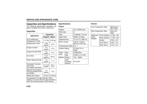
Capacities and SpecificationsThe following approximate capacities are
given in English and metric conversions. CapacitiesSpecifications
EngineChassis
ApplicationCapacities
English Metric
Air Conditioning
Refrigerant R-134a1.41 lbs 0.64 kg
Brake/Clutch Fluid 0.53
quarts0.5 L
Engine Coolant 7.9
quarts7.4 L
Engine Oil with Filter 4.2
quarts4.0 L
Fuel Tank 14.5
gallons55.0 L
Power Steering Fluid 1.2
quarts1.1 L
Automatic Transmis-
sion Fluid
(Complete Overhaul)7.3 ± 0.2
quarts6.9 ±
0.2 L
Manual Transmission
Fluid (Complete Drain
and Refill)1.9
quarts1.8 L
Wheel Nut Torque 81 lb-ft 110 N.m
All capacities are approximate. When
adding, be sure to fill to the approximately
level, as recommended in this manual. Engine 2.0 L DOHC (L6)
VIN Code Z
Type 4-Cylinder / In-Line
Valve Train DOHC 16 Valve
Displacement 121.9 in
3 (1,998 cc)
Bore x stroke 3.39 in x 3.39 in
(86 mm x 86 mm)
Compression Ratio 9.6 : 1
Octane Rating 87 (Ron 91) or
higher
Spark
plugType FLR8LDCU
Gap 0.039 in (1.0 mm)
Battery Rating 12V – 55AH
Cold
Cranking
Ampere610 CCA
Front Suspension Type McPherson
Strut Type
Rear Suspension Type Dual Link
Ty p e
Alignment
(Curb
Weight)Front Camber –0°33’ ± 45’
Rear Camber –1°00’ ± 45’
Caster 4°00’ ± 45’
Front Toe-in 0°00’ ± 10’
Rear Toe-in 0°12’ ± 10’
Page 198 of 226
5-54
SERVICE AND APPEARANCE CARE
85Z14-03E
Dimension Weight
Overall Length 169.1 in (4,295 mm)
Overall Width 67.9 in (1,725 mm)
Overall Height 56.9 in (1,445 mm)
Wheel Base 102.4 in (2,600 mm)
Tread Front 58.3 in (1,480 mm)
Rear 58.3 in (1,480 mm)
Minimum Ground
Clearance6.3 in (160 mm)
Gross Vehicle
Weight RatingSee the safety certifica-
tion label and the tire
information label which
are located on the
driver’s door lock pillar.
Page 199 of 226
5-55SERVICE AND APPEARANCE CARE
85Z14-03E
MEMO
Page 200 of 226
MAINTENANCE SCHEDULE
6
85Z14-03E
MAINTENANCE SCHEDULEGeneral Information ............................................................ 6-1
Maintenance ........................................................................ 6-2