2008 SUBARU OUTBACK window
[x] Cancel search: windowPage 186 of 444
4-8Climate control
Automatic climate control
system (if equipped) NOTE .Operate the automatic climate con-
trol system when the engine is running. . The blower fan rotates at a low
speed when the engine coolant tem-
perature is low.
For efficient defogging or dehumidify-
ing in cold weather, press the “A/C ”
button.. Even when cooling is not necessary,
setting the temperature much lower
than the current outlet air temperature
turns on the air conditioner compres-
sor automatically and the “A/C ”indi-
cator light on the control panel comeson.
The automatic climate control system
automatically controls outlet air tempera-
ture, fan speed, air flow distribution air-
inlet control, and air conditioner compres-
sor operation. It activates when the“ AUTO ”button is pressed, and is used to
maintain a constant, comfortable climate
within the passenger compartment.
The temperature can be set within a range
of 65 to 85 8F (18 to 32 8C). &
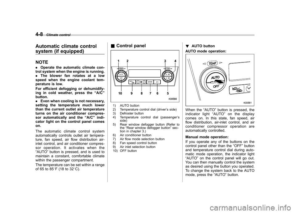
Control panel
1) AUTO button
2) Temperature control dial (driver ’s side)
3) Defroster button
4) Temperature control dial (passenger ’s
side)
5) Rear window defogger button (Refer to the“Rear window defogger button ”sec-
tion in chapter 3.)
6) Air conditioner button
7) Air flow mode selection button
8) Fan speed control button
9) Air inlet selection button
10) OFF button !
AUTO button
AUTO mode operation:
When the “AUTO ”button is pressed, the
indicator light “AUTO ”on the display
comes on. In this state, fan speed, air
flow distribution, air-inlet control, and air
conditioner compressor operation are
automatically controlled.
Manual mode operation:
If you operate any of the buttons on the
control panel other than the “OFF ”button
and temperature control dial during auto-
matic mode operation, the indicator light“ AUTO ”on the control panel will go out.
You can then manually control the system
as desired using the button you operated.
To change the system back to the AUTO
mode, press the “AUTO ”button.
Page 187 of 444
!OFF button
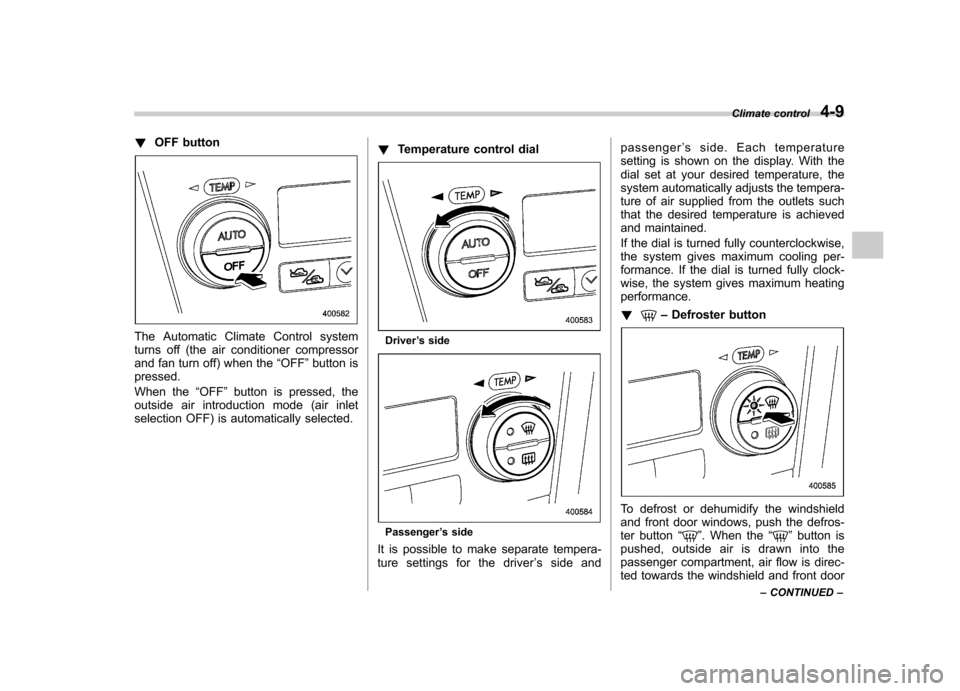
The Automatic Climate Control system
turns off (the air conditioner compressor
and fan turn off) when the “OFF ”button is
pressed.
When the “OFF ”button is pressed, the
outside air introduction mode (air inlet
selection OFF) is automatically selected. !
Temperature control dialDriver ’s side
Passenger ’s side
It is possible to make separate tempera-
ture settings for the driver ’ssideand passenger
’s side. Each temperature
setting is shown on the display. With the
dial set at your desired temperature, the
system automatically adjusts the tempera-
ture of air supplied from the outlets such
that the desired temperature is achieved
and maintained.
If the dial is turned fully counterclockwise,
the system gives maximum cooling per-
formance. If the dial is turned fully clock-
wise, the system gives maximum heatingperformance. !
– Defroster button
To defrost or dehumidify the windshield
and front door windows, push the defros-
ter button “
”. When the “”button is
pushed, outside air is drawn into the
passenger compartment, air flow is direc-
ted towards the windshield and front door Climate control
4-9
– CONTINUED –
Page 188 of 444
4-10Climate control
windows, and the indicator light on the
button comes on.
After eliminating the fogging from the
windshield, return the climate control
system to the AUTO mode by pushingthe “AUTO ”button or turn off by pushing
the “OFF ”button.
Alternatively, push the “
”button again
to return the system to the setting that was
selected before you activated the defros-
ter. ! Fan speed control button
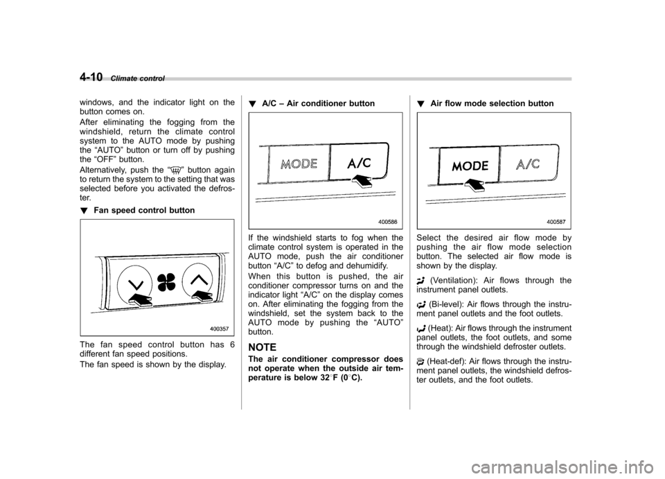
The fan speed control button has 6
different fan speed positions.
The fan speed is shown by the display. !
A/C –Air conditioner button
If the windshield starts to fog when the
climate control system is operated in the
AUTO mode, push the air conditionerbutton “A/C ”to defog and dehumidify.
When this button is pushed, the air
conditioner compressor turns on and the
indicator light “A/C ”on the display comes
on. After eliminating the fogging from the
windshield, set the system back to the
AUTO mode by pushing the “AUTO ”
button.
NOTE
The air conditioner compressor does
not operate when the outside air tem-
perature is below 32 8F(0 8C). !
Air flow mode selection buttonSelect the desired air flow mode by
pushing the air flow mode selection
button. The selected air flow mode is
shown by the display.
(Ventilation): Ai r flows through the
instrument panel outlets.
(Bi-level): Air flows through the instru-
ment panel outlets and the foot outlets.
(Heat): Air flows through the instrument
panel outlets, the foot outlets, and some
through the windshield defroster outlets.
(Heat-def): Air flows through the instru-
ment panel outlets, the windshield defros-
ter outlets, and the foot outlets.
Page 189 of 444

!Air inlet selection button
Select air flow by pushing the air inlet
selection button “/”.
The selected air inlet setting is shown on
the control panel.
(Recirculation): Interior air recirculates
inside the passenger compartment. Use
this position when quickly cooling down
the passenger compartment or to prevent
outside air from entering the passenger
compartment. When the recirculation
mode is selected, a “
”indicator light
appears on the display.
(Outside air): Outside air is drawn into
the passenger compartment. When the
climate control system is operated in the“ AUTO ”mode, this position is selected
automatically. (There is one exception: When the temperature control dial is
turned fully counterclockwise, the recircu-
lation mode is automatically selected.)
When the outside air mode is selected, a“
”
indicator light appears on the dis-
play.
WARNING
Continued operation in the “
”
position may fog up the windows.
Switch to the “
”position as soon
as the outside dusty condition clears.
NOTE
When driving on a dusty road or behind
a vehicle that emits unpleasant exhaust
gases, set the air inlet selection button
to the “
”position.
From time to time, return the air inlet
selection button to the “
”position
to draw outside air into the passenger compartment. &
Temperature sensors
1) Solar sensor
2) Interior air temperature sensor
The automatic climate control system
employs several sensors. These sensors
are delicate. If they are treated incorrectly
and become damaged, the system may
not be able to control the interior tempera-
ture correctly. To avoid damaging the
sensors, observe the following precau-tions: – Do not subject the sensors to impact.
– Keep water away from the sensors.
– Do not cover the sensors.
The sensors are located as follows:– Solar sensor: beside windshield
defroster grille Climate control
4-11
– CONTINUED –
Page 190 of 444

4-12Climate control
–Interior air temperature sensor: on the
side of the driver-side part of the center panel – Outside temperature sensor: behind
front grille. Operating tips for heater and
air conditioner &
Cleaning ventilator grille
Always keep the front ventilator inlet grille
free of snow, leaves, or other obstructions
to ensure efficient heating and defrosting.
Since the condenser is located in front of
the radiator, this area should be kept clean
because cooling performance is impaired
by any accumulation of insects and leaves
on the condenser. &Efficient cooling after parking
in direct sunlight
After parking in direct sunlight, drive with
the windows open for a few minutes to
allow outside air to circulate into the heated interior. This results in quicker
cooling by the air conditioner. Keep the
windows closed during the operation of
the air conditioner for maximum cooling
efficiency. &
Lubrication oil circulation in
the refrigerant circuit
Operate the air conditioner compressor at
a low engine speed (at idle or low driving
speeds) a few minutes each month during
the off-season to circulate its oil. & Checking air conditioning
system before summer sea-son
Check the air conditioner unit for refriger-
ant leaks, hose conditions, and proper
operation each spring. Have your
SUBARU dealer perform this check. & Cooling and dehumidifying in
high humidity and low tem-
perature weather condition
Under certain weather conditions (high
relative humidity, low temperatures, etc.) a
small amount of water vapor emission
from the air outlets may be noticed. This
condition is normal and does not indicate
any problem with the air conditioningsystem.
Page 193 of 444
5-2Audio
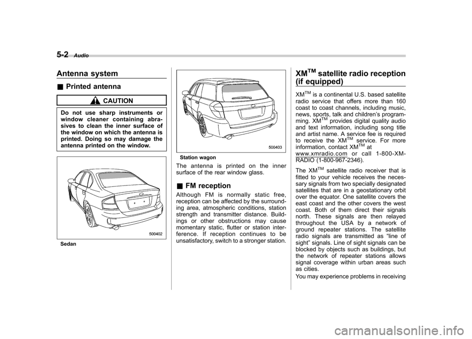
Antenna system &Printed antenna
CAUTION
Do not use sharp instruments or
window cleaner containing abra-
sives to clean the inner surface of
the window on which the antenna is
printed. Doing so may damage the
antenna printed on the window.
Sedan
Station wagon
The antenna is printed on the inner
surface of the rear window glass. & FM reception
Although FM is normally static free,
reception can be affected by the surround-
ing area, atmospheric conditions, station
strength and transmitter distance. Build-
ings or other obstructions may cause
momentary static, flutter or station inter-
ference. If reception continues to be
unsatisfactory, switch to a stronger station. XM
TMsatellite radio reception
(if equipped)
XM
TMis a continental U.S. based satellite
radio service that offers more than 160
coast to coast channels, including music,
news, sports, talk and children ’s program-
ming. XM
TMprovides digital quality audio
and text information, including song title
and artist name. A service fee is required
to receive the XM
TMservice. For more
information, contact XMTMatwww.xmradio.com or call 1-800-XM-
RADIO (1-800-967-2346).
The XM
TMsatellite radio receiver that is
fitted to your vehicle receives the neces-
sary signals from two specially designated
satellites that are in a geostationary orbit
over the equator. One satellite covers the
east coast and the other covers the west
coast. Both of them direct their signals
north. These signals are then relayed
throughout the USA by a network of
ground repeater stations. The satellite
radio signals are transmitted as “line of
sight ”signals. Line of sight signals can be
blocked by objects such as buildings, but
the network of repeater stations allows
signal coverage within urban areas such
as cities.
You may experience problems in receiving
Page 223 of 444
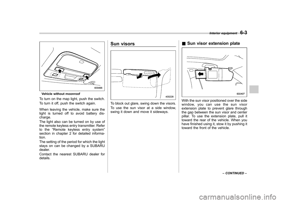
Vehicle without moonroof
To turn on the map light, push the switch.
To turn it off, push the switch again.
When leaving the vehicle, make sure the
light is turned off to avoid battery dis-charge.
The light also can be turned on by use of
the remote keyless entry transmitter. Refer
to the “Remote keyless entry system ”
section in chapter 2 for detailed informa-tion.
The setting of the period for which the light
stays on can be changed by a SUBARU
dealer.
Contact the nearest SUBARU dealer for details. Sun visors
To block out glare, swing down the visors.
To use the sun visor at a side window,
swing it down and move it sideways.
&
Sun visor extension plateWith the sun visor positioned over the side
window, you can use the sun visor
extension plate to prevent glare through
the gap between the sun visor and center
pillar. To use the extension plate, pull it
toward the rear of the vehicle. When you
have finished using it, stow it by pushing it
toward the front of the vehicle. Interior equipment
6-3
– CONTINUED –
Page 249 of 444
7-8Starting and operating
not properly operating or there is one or
more diagnostic trouble codes stored invehicle ’s computer with the “CHECK
ENGINE ”warning light/MIL illuminated.
. A state emission inspection may reject
(not pass or fail) a vehicle if the number of
OBD system readiness monitors “Not
Ready ”is greater than one. Under this
condition, the vehicle operator should be
instructed to drive his/her vehicle for a few
days to set the monitors and return for an
emission re-inspection. . Owners of rejected or failing vehicles
should contact their SUBARU Dealer for service. Preparing to drive
You should perform the following checks
and adjustments every day before you
start driving.
1. Check that all windows, mirrors, and
lights are clean and unobstructed.
2. Check the appearance and condition
of the tires. Also check tires for properinflation.
3. Look under the vehicle for any sign of leaks.
4. Check that the hood, trunk (Sedan)
and rear gate (Station wagon) are fullyclosed.
5. Check the adjustment of the seat.
6. Check the adjustment of the inside
and outside mirrors.
7. Fasten your seatbelt. Check that your
passengers have fastened their seatbelts.
8. Check the operation of the warning
and indicator lights when the ignition
switch is turned to the
“ON ”position.
9. Check the gauges, indicator and warn-
ing lights after starting the engine. NOTE
Engine oil, engine coolant, brake fluid,
washer fluid and other fluid levels
should be checked daily, weekly or at
fuel stops.