Page 374 of 444
11-28Maintenance and service
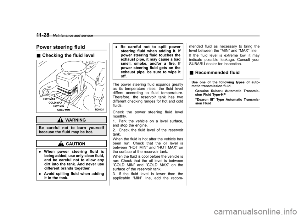
Power steering fluid &Checking the fluid level
WARNING
Be careful not to burn yourself
because the fluid may be hot.
CAUTION
. When power steering fluid is
being added, use only clean fluid,
and be careful not to allow any
dirt into the tank. And never use
different brands together.
. Avoid spilling fluid when adding
it in the tank. .
Be careful not to spill power
steering fluid when adding it. If
power steering fluid touches the
exhaust pipe, it may cause a bad
smell, smoke, and/or a fire. If
power steering fluid gets on the
exhaust pipe, be sure to wipe itoff.
The power steering fluid expands greatly
as its temperature rises; the fluid level
differs according to fluid temperature.
Therefore, the reservoir tank has two
different checking ranges for hot and coldfluids.
Check the power steering fluid level
monthly.
1. Park the vehicle on a level surface,
and stop the engine.
2. Check the fluid level of the reservoir tank.
When the fluid is hot after the vehicle has
been run: Check that the oil level isbetween “HOT MIN ”and “HOT MAX ”on
the surface of the reservoir tank.
When the fluid is cool before the vehicle is
run: Check that the oil level is between“ COLD MIN ”and “COLD MAX ”on the
surface of the reservoir tank.
3. If the fluid level is lower than the
applicable “MIN ”line, add the recom- mended fluid as necessary to bring the
level between the
“MIN ”and “MAX ”line.
If the fluid level is extreme low, it may
indicate possible leakage. Consult your
SUBARU dealer for inspection.
& Recommended fluid
Use one of the following types of auto-
matic transmission fluid. Genuine Subaru Automatic Transmis-
sion Fluid Type-HP “Dexron III ”Type Automatic Transmis-
sion Fluid
Page 377 of 444
Brake booster
If the brake booster does not operate as
described in the following, have it checked
by your SUBARU dealer.
1. With the engine off, depress the brake
pedal several times, applying the same
pedal force each time. The distance the
pedal travels should not vary.
2. With the brake pedal depressed, start
the engine. The pedal should move
slightly down to the floor.
3. With the brake pedal depressed, stop
the engine and keep the pedal depressed
for 30 seconds. The pedal height should
not change.
4. Start the engine again and run for
approximately one minute then turn it off.
Depress the brake pedal several times to
check the brake booster. The brake
booster operates properly if the pedal
stroke decreases with each depression.Brake pedal
Check the brake pedal free play and
reserve distance according to the main-
tenance schedule in the
“Warranty and
Maintenance Booklet ”.
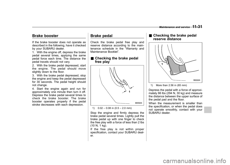
& Checking the brake pedal
free play
1) 0.02 –0.08 in (0.5 –2.0 mm)
Stop the engine and firmly depress the
brake pedal several times. Lightly pull the
brake pedal up with one finger to check
the free play with a force of less than 2 lbs
(10 N, 1 kg).
If the free play is not within proper
specification, contact your SUBARU deal-
er. &
Checking the brake pedal
reserve distance
1) More than 2.56 in (65 mm)
Depress the pedal with a force of approxi-
mately 66 lbs (294 N, 30 kg) and measure
the distance between the upper surface of
the pedal pad and the floor.
When the measurement is smaller than
the specification, or when the pedal does
not operate smoothly, contact with your
SUBARU dealer. Maintenance and service
11-31
Page 378 of 444
11-32Maintenance and service
Clutch pedal (MT models)
Check the clutch pedal free play and
reserve distance according to the main-
tenance schedule in the “Warranty and
Maintenance Booklet ”.
& Checking the clutch function
Check the clutch engagement and disen-gagement.
1. With the engine idling, check that there
are no abnormal noises when the clutch
pedal is depressed, and that shifting into
1st or reverse feels smooth.
2. Start the vehicle by releasing the pedal
slowly to check that the engine and
transmission smoothly couple without
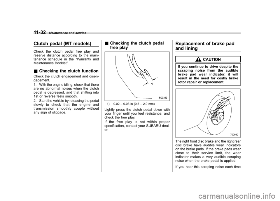
any sign of slippage. &
Checking the clutch pedal
free play
1) 0.02 –0.08 in (0.5 –2.0 mm)
Lightly press the clutch pedal down with
your finger until you feel resistance, and
check the free play.
If the free play is not within proper
specification, contact your SUBARU deal-
er. Replacement of brake pad
and lining
CAUTION
If you continue to drive despite the
scraping noise from the audible
brake pad wear indicator, it will
result in the need for costly brake
rotor repair or replacement.
The right front disc brake and the right rear
disc brake have audible wear indicators
on the brake pads. If the brake pads wear
close to their service limit, the wear
indicator makes a very audible scraping
noise when the brake pedal is applied.
If you hear this scraping noise each time
Page 387 of 444
WARNING
Use only those wheels that are
specified for your vehicle. Wheels
not meeting specifications could
interfere with brake caliper opera-
tion and may cause the tires to rub
against the wheel well housing dur-
ing turns. The resulting loss of
vehicle control could lead to anaccident. Aluminum wheels
Aluminum wheels can be scratched and
damaged easily. Handle them carefully to
maintain their appearance, performance,
and safety. .
When any of the wheels is removed
and replaced for tire rotation or to change
a flat, always check the tightness of the
wheel nuts after driving approximately 600
miles (1,000 km). If any nut is loose,
tighten it to the specified torque. . Never apply oil to the threaded parts,
wheel nuts, or tapered surface of the wheel. . Never let the wheel rub against sharp
protrusions or curbs.. Be sure to fit tire chains on uniformly
and completely around the tire, otherwise
the chains may scratch the wheel. . When wheel nuts, balance weights, or
the center cap is replaced, be sure to
replace them with genuine SUBARU parts
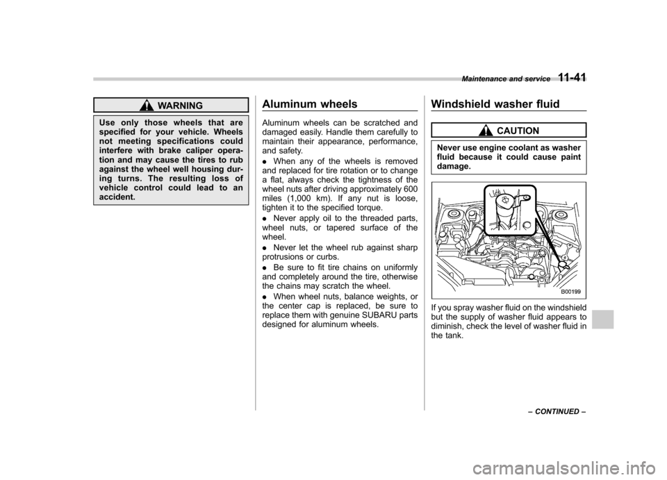
designed for aluminum wheels. Windshield washer fluid
CAUTION
Never use engine coolant as washer
fluid because it could cause paintdamage.
If you spray washer fluid on the windshield
but the supply of washer fluid appears to
diminish, check the level of washer fluid in
the tank. Maintenance and service
11-41
– CONTINUED –
Page 394 of 444
11-48Maintenance and service
Fuses
CAUTION
Never replace a fuse with one hav-
ing a higher rating or with material
other than a fuse because serious
damage or a fire could result.
The fuses are designed to melt during an
overload to prevent damage to the wiring
harness and electrical equipment. The
fuses are located in two fuse boxes. One
is located under the instrument panel
behind the fuse box cover on the driver ’s
seat side.
Open the lid that is located above the
hood release knob and pull it toward you
to remove it.
The other one is housed in the engine compartment.
The spare fuses are stored in the main
fuse box cover in the engine compart-ment.
The fuse puller is stored in the main fuse
box in the engine compartment.
Page 407 of 444
Specifications..................................................... 12-2
Dimensions ........................................................ 12-2
Engine ............................................................... 12-3
Electrical system ................................................ 12-3
Capacities .......................................................... 12-4
Tires .................................................................. 12-5
Wheel alignment ................................................ 12-5 Fuses and circuits
............................................. 12-6
Fuse panel located in the passenger compartment ................................................... 12-6
Fuse panel located in the engine compartment ................................................... 12-8
Bulb chart ........................................................... 12-9
Vehicle identification ....................................... 12-11Specifications
12
Page 409 of 444
&Engine
Engine model EJ253
(2.5-liter, SOHC, non-turbo) EJ255
(2.5-liter, DOHC, turbo) EZ30D
(3.0-liter, DOHC, non-turbo)
Engine type Horizontally opposed, liquid cooled 4 cylinder,
4 stroke gasoline engine Horizontally opposed, liquid cooled 6 cylinder,
4 stroke gasoline engine
Displacement cu-in (cc) 150 (2,457) 183 (3,000)
Bore 6Stroke in (mm) 3.92 63.11 (99.5 679.0) 3.51 63.15 (89.2 680.0)
Compression ratio 10.0 : 1 8.4 : 1 10.7 : 1
Firing order 1– 3–2 – 4 1
–6– 3–2– 5–4
& Electrical system
Battery type and capacity (5HR) 2.5-liter models
MT 55D23L (12V-48AH)
AT 75D23L (12V-52AH)
3.0-liter models 75D23L (12V-52AH)
Alternator 12V-110A
Spark plugs 2.5-liter non-turbo models
FR5AP-11 (NGK)
2.5-liter turbo models SILFR6A (NGK)
3.0-liter models ILFR6B (NGK)Specifications
12-3
– CONTINUED –
Page 410 of 444
12-4Specifications
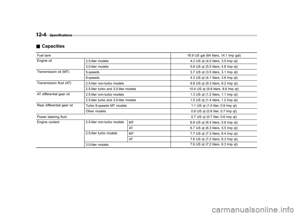
&Capacities
Fuel tank 16.9 US gal (64 liters, 14.1 Imp gal)
Engine oil 2.5-liter models 4.2 US qt (4.0 liters, 3.5 Imp qt)
3.0-liter models 5.8 US qt (5.5 liters, 4.8 Imp qt)
Transmission oil (MT) 5-speeds 3.7 US qt (3.5 liters, 3.1 Imp qt)
6-speeds 4.3 US qt (4.1 liters, 3.6 Imp qt)
Transmission fluid (AT) 2.5-liter non-turbo models 9.8 US qt (9.3 liters, 8.2 Imp qt)
2.5-liter turbo and 3.0-liter models 10.4 US qt (9.8 liters, 8.6 Imp qt)
AT differential gear oil 2.5-liter non-turbo models 1.3 US qt (1.2 liters, 1.1 Imp qt)
2.5-liter turbo and 3.0-liter models 1.5 US qt (1.4 liters, 1.2 Imp qt)
Rear differential gear oil Turbo 6-speeds MT models 1.1 US qt (1.0 liter, 0.9 Imp qt)
Other models 0.8 US qt (0.8 liter, 0.7 Imp qt)
Power steering fluid 0.7 US qt (0.7 liter, 0.6 Imp qt)
Engine coolant 2.5-liter non-turbo models MT6.8 US qt (6.4 liters, 5.6 Imp qt)
AT 6.7 US qt (6.3 liters, 5.5 Imp qt)
2.5-liter turbo models MT 7.7 US qt (7.3 liters, 6.4 Imp qt)
AT 7.6 US qt (7.2 liters, 6.3 Imp qt)
3.0-liter models 7.6 US qt (7.2 liters, 6.3 Imp qt)