2008 Seat Ibiza 5D heater
[x] Cancel search: heaterPage 51 of 260
Cockpit49
Safety First
Operating instructions
Practical tips
Te c h n i c a l D a t a
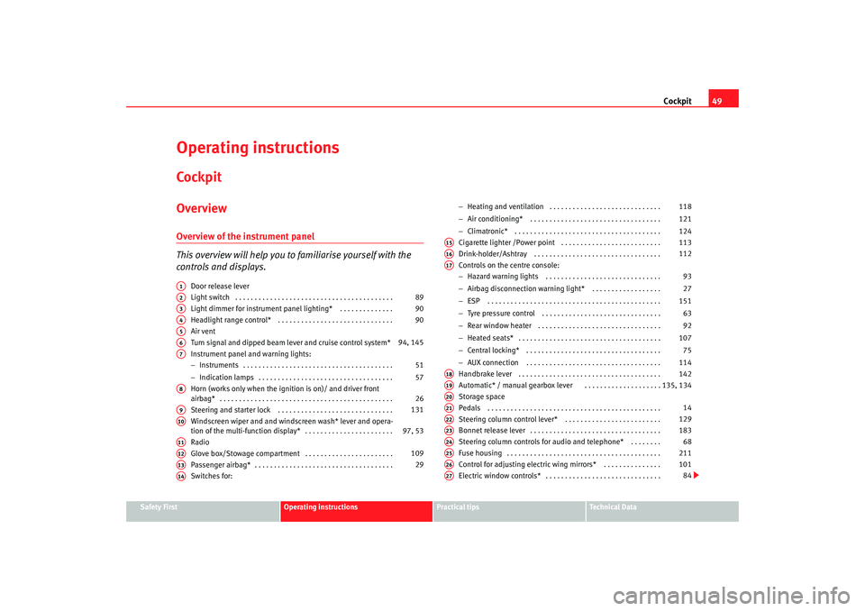
Operating instructionsCockpitOverviewOverview of the instrument panel
This overview will help you to familiarise yourself with the
controls and displays.
Door release lever
Light switch . . . . . . . . . . . . . . . . . . . . . . . . . . . . . . . . . . . . . . . . .
Light dimmer for instrument panel ligh ting* . . . . . . . . . . . . . .
Headlight range control* . . . . . . . . . . . . . . . . . . . . . . . . . . . . . .
Air vent
Turn signal and dipped beam lever and cruise control system*
Instrument panel an d warning lights:
− Instruments . . . . . . . . . . . . . . . . . . . . . . . . . . . . . . . . . . . . . . .
− Indication lamps . . . . . . . . . . . . . . . . . . . . . . . . . . . . . . . . . . .
Horn (works only when the igni tion is on)/ and driver front
airbag* . . . . . . . . . . . . . . . . . . . . . . . . . . . . . . . . . . . . . . . . . . . . .
Steering and starter lock . . . . . . . . . . . . . . . . . . . . . . . . . . . . . .
Windscreen wiper and and windscreen wash* lever and opera-
tion of the multi-function display* . . . . . . . . . . . . . . . . . . . . . . .
Radio
Glove box/Stowage compartment . . . . . . . . . . . . . . . . . . . . . . .
Passenger airbag* . . . . . . . . . . . . . . . . . . . . . . . . . . . . . . . . . . . .
Switches for: −
Heating and ventilation . . . . . . . . . . . . . . . . . . . . . . . . . . . . .
− Air conditioning* . . . . . . . . . . . . . . . . . . . . . . . . . . . . . . . . . .
− Climatronic* . . . . . . . . . . . . . . . . . . . . . . . . . . . . . . . . . . . . . .
Cigarette lighter /Power point . . . . . . . . . . . . . . . . . . . . . . . . . .
Drink-holder/Ashtray . . . . . . . . . . . . . . . . . . . . . . . . . . . . . . . . .
Controls on the centre console:
− Hazard warning lights . . . . . . . . . . . . . . . . . . . . . . . . . . . . . .
− Airbag disconnection warni ng light* . . . . . . . . . . . . . . . . . .
− ESP . . . . . . . . . . . . . . . . . . . . . . . . . . . . . . . . . . . . . . . . . . . . .
− Tyre pressure control . . . . . . . . . . . . . . . . . . . . . . . . . . . . . . .
− Rear window heater . . . . . . . . . . . . . . . . . . . . . . . . . . . . . . . .
− Heated seats* . . . . . . . . . . . . . . . . . . . . . . . . . . . . . . . . . . . . .
− Central locking* . . . . . . . . . . . . . . . . . . . . . . . . . . . . . . . . . . .
− AUX connection . . . . . . . . . . . . . . . . . . . . . . . . . . . . . . . . . . .
Handbrake lever . . . . . . . . . . . . . . . . . . . . . . . . . . . . . . . . . . . . .
A utomatic* / manual gearbox lever
. . . . . . . . . . . . . .
. . . . . .
Storage space
Pedals . . . . . . . . . . . . . . . . . . . . . . . . . . . . . . . . . . . . . . . . . . . . .
Steering column control lever* . . . . . . . . . . . . . . . . . . . . . . . . .
Bonnet release lever . . . . . . . . . . . . . . . . . . . . . . . . . . . . . . . . . .
Steering column controls for audio and telephone* . . . . . . . .
Fuse housing . . . . . . . . . . . . . . . . . . . . . . . . . . . . . . . . . . . . . . . .
Control for adjusting electric wing mirrors* . . . . . . . . . . . . . . .
Electric window controls* . . . . . . . . . . . . . . . . . . . . . . . . . . . . . .
A1A2
89
A3
90
A4
90
A5A6
94, 145
A7
51
57
A8
26
A9
131
A10
97, 53
A11A12
109
A13
29
A14
118
121
124
A15
113
A16
112
A17
93
27
151 63
92
107 75
114
A18
142
A19
135, 134
A20A21
14
A22
129
A23
183
A24
68
A25
211
A26
101
A27
84
Ibiza250_angles Seite 49 Dienstag, 5. August 2008 1:11 13
Page 94 of 260
Lights and visibility
92
– Push the light lever to the main beam position
.
– Dipped headlights come on when the door is opened.
You have 2 mins. from when the key is take n out of the ignition switch to when
the lights flash; after this, the Coming ho me function will not activate. To acti-
vate it again, repeat the operation.
When the system is activated, dipped headlights remain on for 30 secs. after
closing the door. If the door is open for more than 3 mins., the system will not
remain active after the 3 mins., which means that the dipped lights will not
light up.
Note
•
If the vehicle is often used during th e night for short trips and the Coming
home function is used, this will discharge the battery considerably. To avoid
this, make longer journeys whenever possible.
•
Observe all relevant statutory requirements when using the lighting
systems described here.
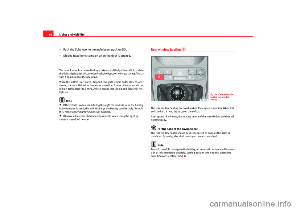
Rear window heating
The rear window heating only works when the engine is running. When it is
switched on, a lamp lights up on the switch.
After approx. 8 minutes, the heating device of the rear window switches off
automatically.
For the sake of the environment
The rear window heater should be disconnected as soon as the glass is
demisted. By saving electrical power you can also save fuel.
Note
To avoid possible damage to the battery, an automatic temporary disconnec-
tion of this function is possible, coming back on when normal operating
conditions are reestablished.
Fig. 54 Centre console:
heated rear window
switch
Ibiza250_angles Seite 92 Dienstag, 5. August 2008 1:11 13
Page 183 of 260
Checking and refilling levels181
Safety First
Operating instructions
Practical tips
Te c h n i c a l D a t a
In countries with different climatic conditions the diesel fuel generally sold
has different temperature characteristics. Check with an Authorised Service
Centre or filling stations in the country concerned regarding the type of diesel
fuels available.
Filter pre-heater
Your vehicle is fitted with a fuel filter pre-heater, making it well equipped for
operation in winter. This ensures that the fuel system remains operational to
approx. -24°C, provided you use winter-grade diesel which is safe to -15°C.
However, if the fuel has waxed to such an extent that the engine will not start
at temperatures of under -24°C, simply place the vehicle in a warm place for
a while.
Caution
Do not mix fuel additives (“thinners”,
or similar additives) with diesel fuel.Working in the engine compartmentSafety instructions on working in the engine compartment
Any work carried out in the engine compartment or on the
engine must be carried out cautiously.Before starting any work on the engine or in the engine compart-
ment:
1. Switch off the engine and remove the key from the ignition.
2. Apply the handbrake.
3. Move the gear stick to neutral or the selector lever to position P. 4. Wait for the engine to cool down.
5. Keep children away from the vehicle.
6. Raise the bonnet
⇒page 183.
You should not do any work in the engine compartment unless you know
exactly how to carry out the jobs and have the correct tools! Have the work
carried out by a qualified workshop if you are uncertain.
All service fluids and consumables, e.g. coolant, engine oil, spark plugs and
batteries, are being constantly developed. SEAT provides a constant flow of
information to the Authorised Service Centres concerning modifications. For
this reason, we recommend you to have service fluids and consumables
replaced by an Authorised Service Centre. Please observe the relevant
instructions ⇒page 173. The engine compartment of any motor vehicle is a
hazardous area ⇒ .
WARNING
All work on the engine or in the en gine compartment, e.g. checking and
refilling fluids, involves the danger of injury and scalding as well as the risk
of accident or fire.•
Never open the bonnet if you see steam, smoke or coolant escaping
from the engine compartment. Otherwise, there is a risk of sustaining
burns. Wait until no more steam or coolant is emitted, then allow the
engine to cool before carefully opening the bonnet.
•
Switch off the engine and remo ve the key from the ignition.
•
Apply the handbrake and move the gear stick to neutral or selector
lever to position P.
•
Keep children away from the vehicle.
•
Never touch hot engine parts. There is a risk of burns.
•
Never spill liquids on a hot engine or on a hot exhaust gas system. This
is a fire hazard.
Ibiza250_angles Seite 181 Dienstag, 5. August 2008 1:11 13
Page 190 of 260
Checking and refilling levels
188•
Before opening the bonnet, read and observe the warnings
⇒ page 181, “Safety instructions on wo rking in the engine compartment”.
•
Wait for the engine to cool down. Hot oil may cause burn injuries.
•
Wear eye protection to avoid injuries caused by splashes of oil.
•
When removing the oil drain plug with your fingers, keep your arm hori-
zontal to help prevent oil from running down your arm.
•
Wash your skin thoroughly if it comes into contact with engine oil.
•
Engine oil is poisonous! Used oil must be stored in a safe place out of
the reach of children until it is disposed of.Caution
No additives should be used with engine oil. This could result in engine
damage. Any damage caused by the use of such additives would not be
covered by the factory warranty.
For the sake of the environment
•
Because of the disposal problems, the necessary special tools and
specialist knowledge required, we recommend that you have the engine oil
and filter changed by an Authorised Service Centre.
•
Never pour oil down drains or into the ground.
•
Use a suitable container when draining the used oil. It has to be large
enough to hold all the engine oil.
CoolantCoolant specifications
Coolant is a mixture of water and at least 40% coolant addi-
tive.The cooling system must be filled with a mixture of water and at least 40% of
our coolant additive G 12++ or an additive with the specification TT-VW 774 G
(recognised by its purple colour). T his mixture gives the necessary frost
protection down to -25°C and protects the alloy parts of the cooling system
against corrosion. It also prevents scal ing and raises the boiling point of the
coolant.
The concentration of coolant must always be at least 40% - even if frost
protection is not required.
If greater frost protection is required in very cold climates, the proportion of
the antifreeze additive G 12++ can be increased. However, the percentage of
coolant additives should not exceed 60%, as this would reduce the frost
protection. It would also reduce the cooling effect. A mixture with 60%
coolant additive will give frost protection to approx. -40°C.
WARNING
•
The coolant additive is toxic. Ther e is a toxic risk. Always keep the
coolant additive in the original container which should be stored out of the
reach of children. The same applies to coolant which you have drained off.
•
The coolant additive G 12++ must be added in sufficient quantities to
provide anti-freeze protection at the coldest ambient temperatures that
can be expected. At extremely cold ambient temperatures, the coolant
could freeze, causing the vehicle to breakdown. As the heater would also
not work in this situation, there is a risk of suffering exposure!
WARNING (continued)
Ibiza250_angles Seite 188 Dienstag, 5. August 2008 1:11 13
Page 216 of 260
If and when
214
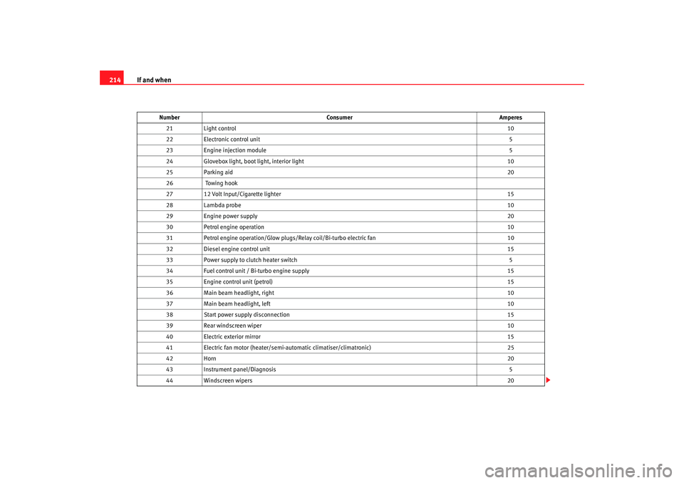
21 Light control 10
22 Electronic control unit 5
23 Engine injection module 5
24 Glovebox light, boot light, interior light 10
25 Parking aid 20
26 Towing hook
27 12 Volt Input/Cigarette lighter 15
28 Lambda probe 10
29 Engine power supply 20
30 Petrol engine operation 10
31 Petrol engine operation/Glow plugs/Relay coil/Bi-turbo electric fan 10
32 Diesel engine control unit 15
33 Power supply to clutch heater switch 5
34 Fuel control unit / Bi-turbo engine supply 15
35 Engine control unit (petrol) 15
36 Main beam headlight, right 10
37 Main beam headlight, left 10
38 Start power supply disconnection 15
39 Rear windscreen wiper 10
40 Electric exterior mirror 15
41 Electric fan motor (heater/semi-automatic climatiser/climatronic) 25
42 Horn 20
43 Instrument panel/Diagnosis 5
44 Windscreen wipers 20
Number
Consumer Amperes
Ibiza250_angles Seite 214 Dienstag, 5. August 2008 1:11 13
Page 217 of 260
If and when215
Safety First
Operating instructions
Practical tips
Te c h n i c a l D a t a
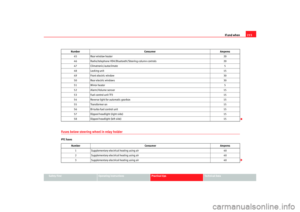
Fuses below steering wheel in relay holderPTC fuses45
Rear window heater 20
46 Radio/telephone VDA/Bluetooth/Steering column controls 20
47 Climatronic/autoclimate 5
48 Locking unit 15
49 Front electric window 30
50 Rear electric windows 30
51 Mirror heater 5
52 Alarm/Volume sensor 15
53 Fuel control unit TF3 15
54 Reverse light for automatic gearbox 15
55 Transformer on 15
56 Bi-turbo fuel control unit 15
57 Dipped headlight (right side) 15
58 Dipped headlight (left side) 15
Number Consumer Amperes
1 Supplementary electrical heating using air 40
2 Supplementary electrical heating using air 40
3 Supplementary electrical heating using air 40
Number
Consumer Amperes
Ibiza250_angles Seite 215 Dienstag, 5. August 2008 1:11 13
Page 219 of 260
If and when217
Safety First
Operating instructions
Practical tips
Te c h n i c a l D a t a
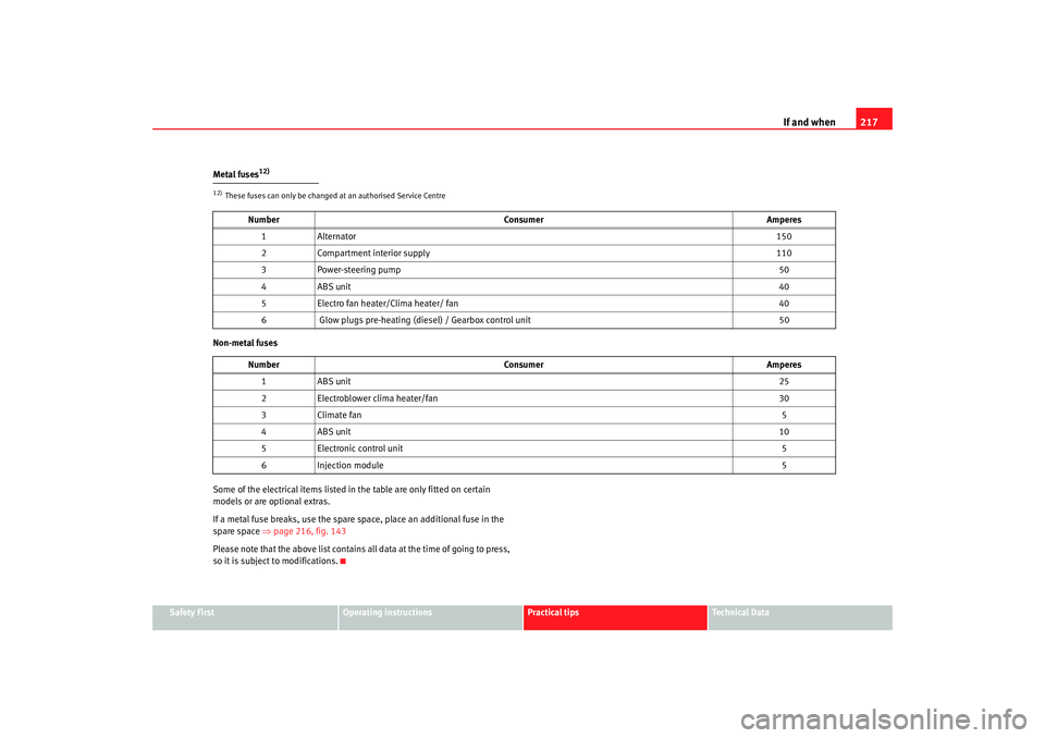
Metal fuses
12)
Non-metal fuses
Some of the electrical items listed in
the table are only fitted on certain
models or are optional extras.
If a metal fuse breaks, use the spare space, place an additional fuse in the
spare space ⇒page 216, fig. 143
Please note that the above list contains all data at the time of going to press,
so it is subject to modifications.12)These fuses can only be changed at an authorised Service Centre
Number Consumer Amperes
1A lt e rn ato r 150
2 Compartment interior supply 110
3 Power-steering pump 50
4A BS u nit 40
5 Electro fan heater/Clima heater/ fan 40
6 Glow plugs pre-heating (diesel) / Gearbox control unit 50
Number Consumer Amperes
1A BS u nit 25
2 Electroblower clima heater/fan 30
3 Climate fan 5
4A BS u nit 10
5 Electronic control unit 5
6 Injection module 5
Ibiza250_angles Seite 217 Dienstag, 5. August 2008 1:11 13
Page 229 of 260
If and when227
Safety First
Operating instructions
Practical tips
Te c h n i c a l D a t a
Jump leads
Jump leads must comply with the standard
DIN 72553 (see manufacturer's
documentation). The wire cross section must be at least 25 mm
2 for petrol
engines and at least 35 mm
2 for diesel engines.
Note
•
The vehicles must not touch each other, otherwise electricity could flow as
soon as the positive terminals are connected.
•
The discharged battery must be properly connected to the vehicle elec-
trical system.
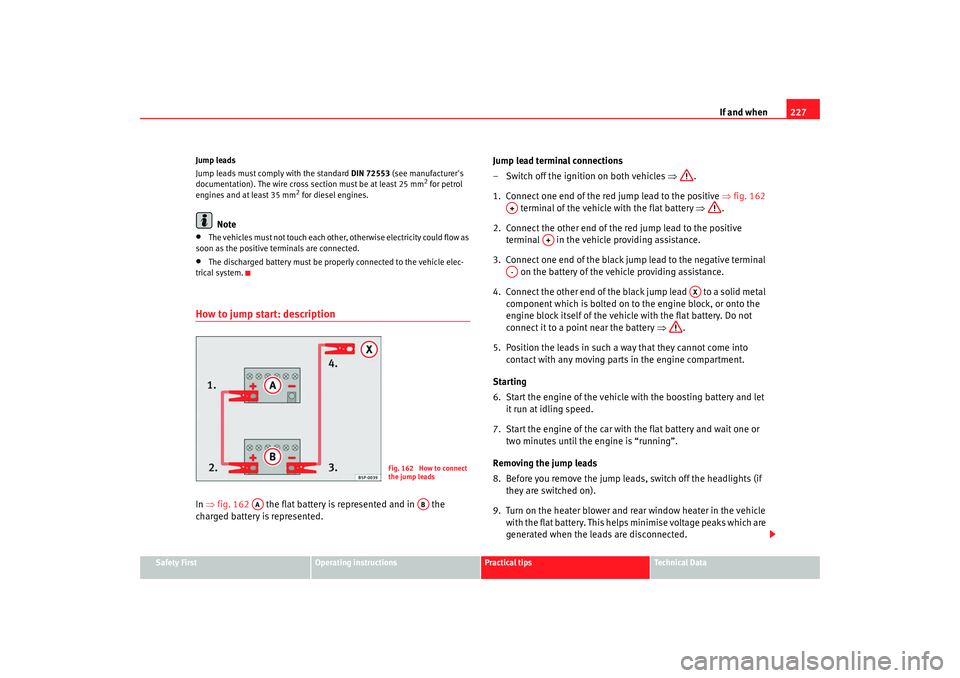
How to jump start: descriptionIn ⇒ fig. 162 the flat battery is represented and in the
charged battery is represented. Jump lead terminal connections
– Switch off the ignition on both vehicles
⇒.
1. Connect one end of the red jump lead to the positive ⇒fig. 162
terminal of the vehicle with the flat battery ⇒.
2. Connect the other end of the red jump lead to the positive terminal in the vehicle providing assistance.
3. Connect one end of the black jump lead to the negative terminal on the battery of the vehicle providing assistance.
4. Connect the other end of the black jump lead to a solid metal component which is bolted on to the engine block, or onto the
engine block itself of the vehicle with the flat battery. Do not
connect it to a point near the battery ⇒.
5. Position the leads in such a way that they cannot come into contact with any moving parts in the engine compartment.
Starting
6. Start the engine of the vehicle with the boosting battery and let
it run at idling speed.
7. Start the engine of the car with the flat battery and wait one or two minutes until the engine is “running”.
Removing the jump leads
8. Before you remove the jump leads, switch off the headlights (if they are switched on).
9. Turn on the heater blower and rear window heater in the vehicle with the flat battery. This helps minimise voltage peaks which are
generated when the leads are disconnected.
Fig. 162 How to connect
the jump leads
AA
AB
A+
A+
A-
AX
Ibiza250_angles Seite 227 Dienstag, 5. August 2008 1:11 13