2008 RENAULT SCENIC ignition
[x] Cancel search: ignitionPage 3 of 94

ENGINE COMPARTMENT CONNECTION UNIT
Fault finding - Introduction87G
87G - 3V7 MR-372-J84-87G050$055.mif
UPC
Vdiag No.: 48, 4C
3. REMINDER
PROCEDURE
To run fault finding on the vehicle's computers, switch on the ignition in fault finding mode (forced + after ignition
feed). Run the self-test procedure for the UPC internal relays and fuses using AC016 Electrical supply circuit
test.
Depending on the type of vehicle equipment, proceed as follows:
To cut off the + after ignition feed, proceed as follows:
Faults
Faults are declared as either present or stored (depending on whether they appeared in a certain context and have
disappeared since, or whether they remain present but have not been diagnosed within the current context).
The present or stored status of faults should be taken into consideration when the diagnostic tool is used following
the + after ignition supply being switched on (without operating the system components).
For a present fault, apply the procedure described in the Interpretation of faults section.
For a stored fault, note the faults displayed and apply the instructions in the Notes section.
If the fault is confirmed when the instructions in the Notes section are applied, the fault is present. Deal with the fault
If the fault is not confirmed, check:
–the electrical lines which correspond to the fault,
–the connectors on these lines (corrosion, bent pins, etc.),
–the resistance of the component detected as faulty,
–the condition of the wires (melted or split insulation, wear). WARNING
Switch off all unnecessary consumers:
–Radio navigation system.
–Switch the passenger compartment ventilation speed to 0.
–Switch off the interior lights (forced off).
With the vehicle card in the card reader, press and hold the start button (+ 5 seconds) outside starting conditions,
connect the diagnostic tool and carry out the required operations.
Press the start button twice briefly (less than 3 seconds); check that the + after ignition feed has cut (computer
indicator lights on the instrument panel go out).
Page 8 of 94

ENGINE COMPARTMENT CONNECTION UNIT
Fault finding - System operation87G
87G-8V7 MR-372-J84-87G050$110.mif
UPC
Vdiag No.: 48, 4CENGINE COMPARTMENT CONNECTION UNIT
Fault finding - System operation
General operation
The Protection and Switching Unit is involved in the following functions:
–Access - Safety.
–Air conditioning.
–Lighting.
–Wipers.
–Charging circuit.
–Oil pressure detection.
–Electric power distribution.
1 - Electric power distribution
The main function of the Protection and Switching Unit is to switch and distribute the power supply to the vehicle's
systems, actuators or computers.
Part of this function is handled within the unit, but it is not electronically controlled by the computer.
+ 12 V battery feed
The Protection and Switching Unit receives energy from the battery via the Busbar and MM connectors (tracks 6 and
4) and redistributes the + 12 V feed.
+ 12 V after ignition
The UCH sends the Protection and Switching Unit the + 12 V after ignition feed request via the multiplex network.
When the Protection and Switching Unit receives this request, it actuates the after ignition relay unconditionally. The
signal is distributed to the sensors, actuators and computers.
2 - Charge circuit
One of the main functions of the Protection and Switching Unit is managing the charge circuit.
Purpose and components:
The main function of the charging circuit is to produce and distribute the electrical energy required to operate the
various electrical consumers on the vehicle (computers, lights, etc.).
It is also used to start the engine.
The main components are a battery, an alternator and a starter motor.
MR-372-J84-87G050$110.mif
Page 9 of 94

ENGINE COMPARTMENT CONNECTION UNIT
Fault finding - System operation87G
87G-9V7 MR-372-J84-87G050$110.mif
UPC
Vdiag No.: 48, 4C
a) Battery
The principal purpose of the battery is to provide the powerful current briefly required by the starter motor to start the
engine. For optimum starting, the current supplied by the battery must be sent to the starter motor with minimum
loss. To achieve this, the electrical connections (wires, terminals, connectors, etc.) must be in good condition.
When the engine is not running, the battery must feed the accessories that operate constantly, even with the ignition
switched off, such as the alarm, radio codes, computers, etc.
–PR004 Battery voltage represents the supply voltage of the Protection and Switching Unit.
–PR008 Battery voltage after rest represents the battery charge status. If PR008 is less than 12.1 V
(battery discharged) during the first few miles, a "Charge battery" message is displayed on the instrument panel.
The Protection and Switching Unit determines what the voltage across the battery terminals should be, based on the
battery charge status, the operating phase and the battery temperature.
To obtain this voltage, the Protection and Switching Unit actuates the alternator.
b) Alternator
The alternator only operates when the engine is running. Its function is to recharge the battery, and at the same time
to supply the electrical power required to operate all the electrical accessories on the vehicle.
The Protection and Switching Unit is linked to the alternator by a serial connection. The Protection and Switching
Unit and the alternator communicate via this connection.
Alternator management is therefore completely new in relation to previous Renault vehicles.
The Protection and Switching Unit intelligently manages the alternator regulation voltage according to the engine
phase, the battery charge and the temperature.
The alternator sends the Protection and Switching Unit the following signals:
–Type of alternator: the Protection and Switching Unit configures itself according to the alternator specifications.
The Protection and Switching Unit can detect electrical or communication faults on this connection and signal them
using fault DF007 UPC - Alternator connection.
When the battery charge and PR008 Battery voltage after rest decline, the Protection and Switching Unit can
temporarily increase the alternator voltage by 1 V for a duration of 30 minutes after starting.
Before the engine is started and during starting, the alternator voltage is fixed at 10.6 V.
A maximum of 30 seconds after the engine is started, the Protection and Switching Unit sets the alternator voltage
at the optimum calculated value.Note:
A battery must always be fully charged, even when stored.
Page 13 of 94

ENGINE COMPARTMENT CONNECTION UNIT
Fault finding - Replacement of components87G
87G - 13V7 MR-372-J84-87G050$165.mif
UPC
Vdiag No.: 48, 4CENGINE COMPARTMENT CONNECTION UNIT
Fault finding - Replacement of components
To remove and refit the UPC computer:
–Mégane (see MR 364, Mechanical, 87G, Engine compartment connection unit: Removal - Refitting).
–Scénic (see MR 370, Mechanical, 87G, Engine compartment connection unit: Removal - Refitting).
Once this operation is complete, run VP004 Vehicle parameters (see Configurations and programming).
Switch the ignition off and on again for the configurations to be recognised.
IMPORTANT
Removing or replacing the Protection and Switching Unit computer relays is forbidden.
MR-372-J84-87G050$165.mif
Page 14 of 94

ENGINE COMPARTMENT CONNECTION UNIT
Fault finding - Configurations and programming87G
87G-14V7 MR-372-J84-87G050$220.mif
UPC
Vdiag No.: 48, 4CENGINE COMPARTMENT CONNECTION UNIT
Fault finding - Configurations and programming
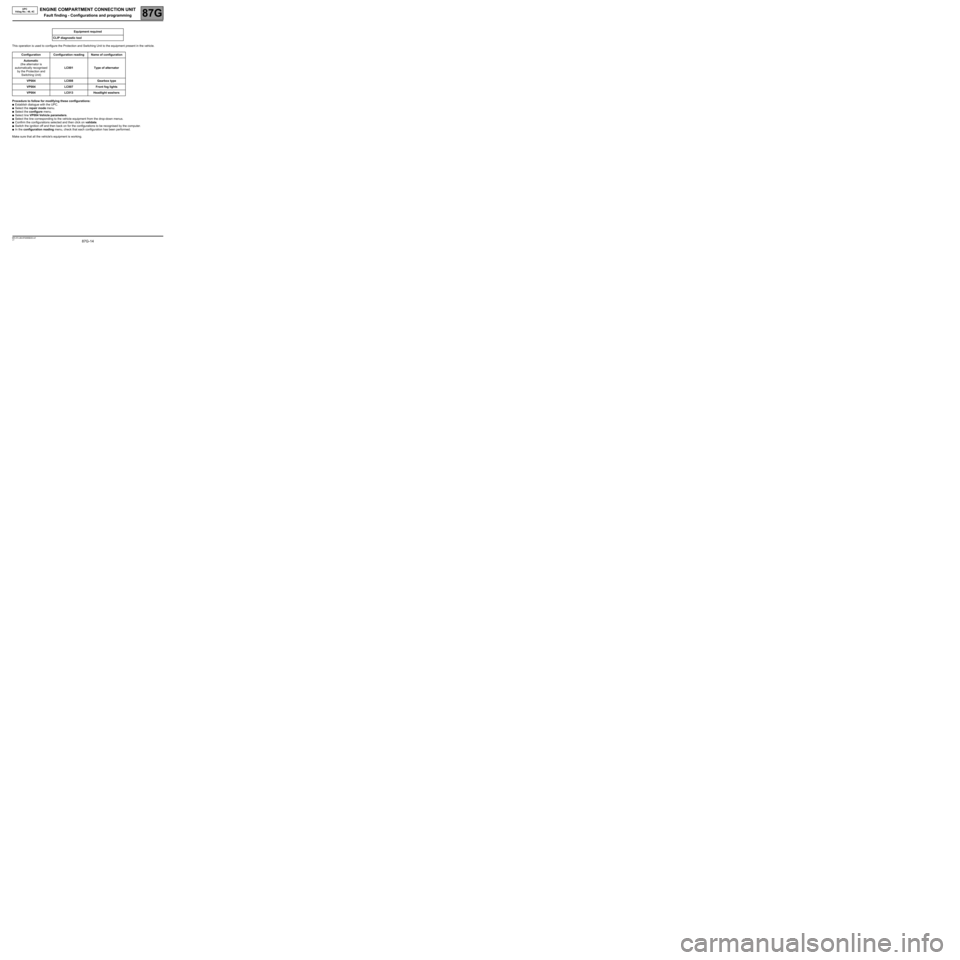
This operation is used to configure the Protection and Switching Unit to the equipment present in the vehicle.
Procedure to follow for modifying these configurations:
●Establish dialogue with the UPC.
●Select the repair mode menu.
●Select the configure menu.
●Select line VP004 Vehicle parameters.
●Select the line corresponding to the vehicle equipment from the drop-down menus.
●Confirm the configurations selected and then click on validate.
●Switch the ignition off and then back on for the configurations to be recognised by the computer.
●In the configuration reading menu, check that each configuration has been performed.
Make sure that all the vehicle's equipment is working.Equipment required
CLIP diagnostic tool
Configuration Configuration reading Name of configuration
Automatic
(the alternator is
automatically recognised
by the Protection and
Switching Unit)LC001 Type of alternator
VP004 LC008 Gearbox type
VP004 LC007 Front fog lights
VP004 LC013 Headlight washers
MR-372-J84-87G050$220.mif
Page 15 of 94

ENGINE COMPARTMENT CONNECTION UNIT
87G
87G - 15V7 MR-372-J84-87G050$275.mif
UPC
Vdiag No.: 48, 4CENGINE COMPARTMENT CONNECTION UNIT
Fault finding - Fault summary table
Summary of faults on which fault finding can be performed by the Protection and Switching Unit.
(With corresponding design office codes).
Tool fault Associated DTC Diagnostic tool title
DF006 920E COMPUTER
DF007 9211 UPC - ALTERNATOR CONNECTION
DF009 9214 + AFTER IGNITION FEED CIRCUIT (Vdiag 4C only)
DF012 9210 ALTERNATOR
DF013 920F VOLTAGE REGULATION
DF014 9217 LEFT-HAND SIDE LIGHT CIRCUIT
DF015 9218 RIGHT-HAND SIDE LIGHT CIRCUIT
DF016 9215 LEFT-HAND DIPPED HEADLIGHT CIRCUIT
DF017 9216 RIGHT-HAND DIPPED HEADLIGHT CIRCUIT
DF018 921B LEFT-HAND MAIN BEAM HEADLIGHT CIRCUIT
DF019 921C RIGHT-HAND MAIN BEAM HEADLIGHT CIRCUIT
DF020 921D FRONT FOG LIGHT CIRCUIT
DF021 9226 REVERSING LIGHT(S) CIRCUIT
DF022 921E REAR SCREEN DE-ICER CIRCUIT
DF023 921A WINDSCREEN WIPER CIRCUIT
DF024 9222 GAS COMPUTER SUPPLY
DF025 9223 ELECTRIC POWER ASSISTED STEERING/AIRBAG
SUPPLY
DF026 9224 AUTOMATIC GEARBOX SUPPLY
DF027 9225 ACCESSORIES SUPPLY
DF029 9221 INJECTION/STEERING COLUMN LOCK SUPPLY
DF030 9219 CLIMATE CONTROL COMPRESSOR SUPPLY CIRCUIT
DF031 921F HEADLIGHT WASHER SUPPLY CIRCUIT
DF032 9227 +12 V RELAY SUPPLY CIRCUIT
DF033 9229 FAN ASSEMBLY SUPPLY CIRCUIT
DF034 9212 ALTERNATOR TYPE
DF035 9213 COMPUTER SUPPLY VOLTAGE
DF036 9220 STEERING COLUMN LOCK SUPPLY CIRCUIT
MR-372-J84-87G050$275.mif
Page 16 of 94

ENGINE COMPARTMENT CONNECTION UNIT
Fault finding - Interpretation of faults87G
87G-16V7 MR-372-J84-87G050$330.mif
UPC
Vdiag No.: 48, 4CENGINE COMPARTMENT CONNECTION UNIT
Fault finding - Interpretation of faults
DF006
PRESENT
OR
STOREDCOMPUTER
1.DEF: Internal electrical fault
NOTESConditions for applying the fault finding procedure to stored faults
The fault is declared present after the ignition is switched off and back on.
If the fault is present, contact Techline.
AFTER REPAIRErase the faults from the computer memory, switch the + after ignition supply off and
back on again and run another check using the diagnostic tool.
USM_V48_DF006/USM_V4C_DF006
MR-372-J84-87G050$330.mif
Page 17 of 94

ENGINE COMPARTMENT CONNECTION UNIT
Fault finding - Interpretation of faults87G
87G-17V7 MR-372-J84-87G050$330.mif
UPC
Vdiag No.: 48, 4C
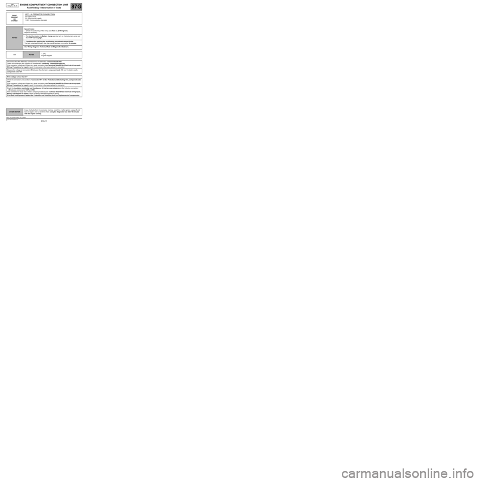
DF007
PRESENT
OR
STOREDUPC - ALTERNATOR CONNECTION
CO: Open circuit
CC: Short circuit to earth
1.DEF: Communication disrupted
NOTESSpecial notes:
–Check the conformity of the wiring (see Test no. 2 Wiring test).
Repair if necessary.
–The fault illuminates the Battery charge warning light on the instrument panel and
the STOP warning light.
–Conditions for applying the fault finding procedure to stored faults:
The fault is declared present after the engine has been running for 10 minutes.
Use Wiring Diagrams Technical Note for Mégane II or Scénic II.
CO
NOTES+ APC.
Engine stopped.
Disconnect the UPC-Alternator connection for the alternator component code 103.
Check the connection and condition of the alternator connector, component code 103.
If the connector is faulty and if there is a repair procedure (see Technical Note 6015A, Electrical wiring repair,
Wiring: Precautions for repair), repair the connector, otherwise replace the connector.
Measure the voltage on connection 2N between the alternator, component code 103 and the battery earth,
component code 107.
If the voltage is less than 3 V
Check the connection and condition of connector MT1 for the Protection and Switching Unit, component code
1337.
If the connector is faulty and if there is a repair procedure (see Technical Note 6015A, Electrical wiring repair,
Wiring: Precautions for repair), repair the connector, otherwise replace the connector.
Check the insulation, continuity and the absence of interference resistance on the following connection:
–2N between components 1337 and 103.
If the connection is faulty and if there is a repair procedure (see Technical Note 6015A, Electrical wiring repair,
Wiring: Precautions for repair), repair the wiring otherwise replace the wiring.
If the fault is still present, replace the Protection and Switching Unit (see Replacement of components).
AFTER REPAIRErase the faults from the computer memory, switch the + after ignition supply off and
back on again, and run another check using the diagnostic tool after 10 minutes
with the engine running.
USM_V48_DF007/USM_V4C_DF007