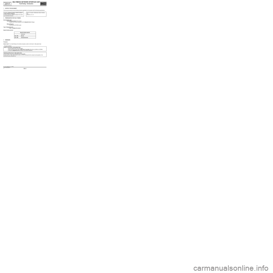
Page 2 of 46

86D-2
MR-372-J84-86D000$056.mif
V2
86D
MULTIMEDIA NETWORK INTERFACE UNIT
Fault finding - Introduction
1. SCOPE OF THIS DOCUMENT
This document presents the fault finding procedure applicable to all computers with the following specifications:
2. PREREQUISITES FOR FAULT FINDING
Documentation type
Fault finding procedure (this manual):
–Assisted fault finding (integrated into the diagnostic tool), Dialogys.
Wiring Diagrams:
–Visu-Schéma (CD-ROM), paper.
Type of diagnostic tools
–CLIP + multiplex line sensor
Special tooling required
3. REMINDERS
Procedure
Scénic II ph2: To run fault finding on the vehicle computers, switch on the forced + after ignition feed.
Proceed as follows: Vehicle(s): Espace IV phase 2, Scénic II phase 2,
Trafic II phase 2, Kangoo 2
Function concerned: Interface between the vehicle
and multimedia networksName of computer: Multimedia network interface
unit
VDIAG No.: 04, 14
Special tooling required
Multimeter
Elé. 1481 Bornier
Elé. 1681 Universal bornier
Switch on the forced + after ignition feed:
–with the vehicle card in the card reader,
–press and hold the Start button (longer than 5 seconds) with start-up conditions not fulfilled,
–connect the diagnostic tool and perform the required operations.
Switching off the forced + after ignition feed:
Press the Start button twice briefly (less than 3 seconds).
Ensure that the + after ignition feed has been cut off by checking that the computer warning lights on the
instrument panel have gone out.
BIC_V04_PRELI/BIC_V14_PRELI
Multimedia network
interface unit
Vdiag No.: 04, 14
MR-372-J84-86D000$056.mif
Page 33 of 46

86D-33
MR-372-J84-86D000$784.mif
V2
MULTIMEDIA NETWORK INTERFACE UNIT
Fault finding - Interpretation of parameters
Multimedia network
interface unit
Vdiag No.: 04, 14
86D
PR004
EXTERNAL TEMPERATURE
NOTESThere must be no present or stored faults.
Engine stopped, ignition on.
Use the wiring diagrams Technical Note for Scénic II ph2, Espace IV ph2, Trafic II
ph2 or Kangoo 2.
Carry out a fault finding procedure on the computer sending the exterior temperature signal:
–Scénic II ph2, Kangoo2, see 87B, Passenger compartment connection unit
–Espace IV ph2, see 83A, Instrument panel
For Trafic II ph2, check the condition and connection of the connector of component 1714 and the connector of
component 240.
If the connector(s) is faulty and if there is a repair procedure (see Technical Note 6015A, Repairing electrical
wiring, W iring: Precautions for repair), repair the connector, otherwise replace the wiring.
Check the insulation, continuity and the absence of interference resistance of the following connections:
–connection code 47C,
–connection code 47D,
between components 1714 and 240.
If the connection or connections are faulty and there is a repair procedure (see Technical Note 6015A, Electrical
wiring repair, Wiring: Precautions for repair), repair the wiring, otherwise replace it.
If the temperature measured by the sensor does not correspond to the exterior temperature, measure the
resistance of the sensor between connections 47C and 47D.
The resistance should be approximately 3000 Ω ± 300 Ω at 20˚C.
Replace the sensor if it is not correct (see MR 408 (TRAFIC), Mechanical, 84A, Control - Signals, Temperature
sensor: Removal - Refitting).
If the fault is still present, contact the techline.
AFTER REPAIRRepeat the conformity check from the start.
BIC_V04_PR004/BIC_V14_PR004
Page 45 of 46

86D-45
MR-372-J84-86D000$952.mif
V2
MULTIMEDIA NETWORK INTERFACE UNIT
Fault finding - Fault Finding Chart
Multimedia network
interface unit
Vdiag No.: 04, 14
86D
ALP 5 Exterior temperature display fault
NOTESSwitch on the + after ignition feed to enter fault finding mode with the computer.
Use the W iring Diagrams Technical Note, Trafic II ph2.
Carry out a fault finding procedure on the computer sending the exterior temperature signal:
–Scénic II ph2, Kangoo 2, see 87B, Passenger compartment connection unit.
–Espace IV ph2, see 83A, Instrument panel.
For Trafic II ph2, check the condition and connection of the connector of component 1714 and the connector of
component 240.
If the connector(s) is faulty and if there is a repair procedure (see Technical Note 6015A, Repairing electrical
wiring, W iring: Precautions for repair), repair the connector, otherwise replace the wiring.
Check the insulation, continuity and the absence of interference resistance of the following connections:
–connection code 47C,
–connection code 47D,
between components 1714 and 240.
If the connection or connections are faulty and there is a repair procedure (see Technical Note 6015A, Electrical
wiring repair, Wiring: Precautions for repair), repair the wiring, otherwise replace it.
If the temperature measured by the sensor does not correspond to the external temperature, measure the sensor
resistance between connections 47C and 47D.
The resistance should be approximately 3000 Ω ± 300 Ω at 20˚C.
Replace the sensor if it is not correct (see MR 408, TRAFIC, Mechanical, 84A, Control - Signals, Temperature
sensor: Removal - Refitting).
If the fault is still present, contact the techline.
AFTER REPAIRCarry out a complete check with the diagnostic tool.
BIC_V04_ALP5/BIC_V14_ALP5