2008 NISSAN TITAN warning
[x] Cancel search: warningPage 382 of 408
TOWING SAFETY
Trailer hitch
Your vehicle may be equipped with an optional
trailer tow package. The trailer tow package in-
cludes a receiver-type frame mounted hitch. This
hitch is rated for the maximum towing capacity of
this vehicle when the proper towing equipment is
used. Choose a proper ball mount and hitch ball
that is rated for the trailer to be towed. Genuine
Nissan ball mounts and hitch balls are available
from your NISSAN dealer.
If your vehicle is not equipped with the optional
trailer tow package, check the towing capacity of
your bumper hitch or receiver-type frame
mounted hitch. Choose a proper hitch for your
vehicle and trailer. A genuine Nissan trailer hitch
is available from your NISSAN dealer. Make sure
the trailer hitch is securely attached to the vehicle
to help avoid personal injury or property damage
due to sway caused by crosswinds, rough road
surfaces or passing trucks.
A hitch used for towing 5th wheel and gooseneck
trailers can also be installed on your vehicle.
Contact a professional supplier of towing equip-
ment to purchase and have a 5th wheel or goose-
neck hitch installed.
WARNING
Trailer hitch components have specific
weight ratings. Your vehicle may be ca-
pable of towing a trailer heavier than the
weight rating of the hitch components.
Never exceed the weight rating of the
hitch components. Doing so can cause
serious personal injury or property
damage.
Hitch ball
Choose a hitch ball of the proper size and weight
rating for your trailer:
cThe required hitch ball size is stamped on
most trailer couplers. Most hitch balls also
have the size printed on the top of the ball.
cChoose the proper class hitch ball based on
the trailer weight.
cThe diameter of the threaded shank of the
hitch ball must be matched to the ball mount
hole diameter. The hitch ball shank should
be no more than 1/16” smaller than the hole
in the ball mount.
cThe threaded shank of the hitch ball must be
long enough to be properly secured to the
ball mount. There should be at least 2
threads showing beyond the lock washer
and nut.
Ball mount
The hitch ball is attached to the ball mount and
the ball mount is inserted into the hitch receiver.
Choose a proper class ball mount based on the
trailer weight. Additionally, the ball mount should
be chosen to keep the trailer tongue level with the
ground.
9-32Technical and consumer information
ZREVIEW COPYÐ2008 Titan(tzw)
Owners ManualÐUSA_English(nna)
03/06/07Ðtbrooks
X
Page 383 of 408
Bumper towing
The genuine NISSAN step bumper has provi-
sions to install a trailer hitch ball and is designed
to tow trailers of a maximum weight of 5,000 lb
(2,268 kg) .
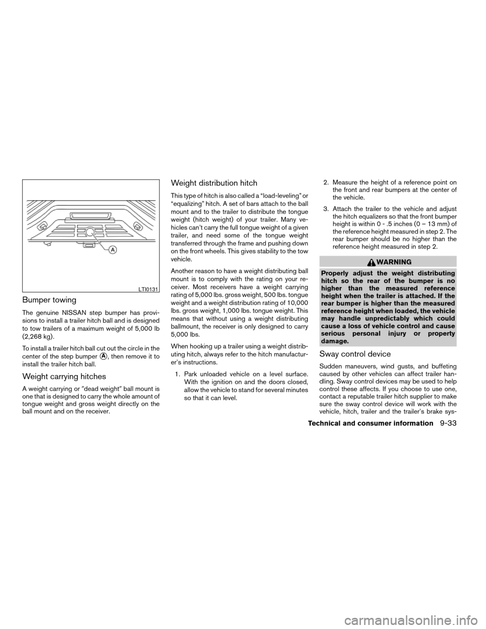
To install a trailer hitch ball cut out the circle in the
center of the step bumper
sA, then remove it to
install the trailer hitch ball.
Weight carrying hitches
A weight carrying or9dead weight9ball mount is
one that is designed to carry the whole amount of
tongue weight and gross weight directly on the
ball mount and on the receiver.
Weight distribution hitch
This type of hitch is also called a “load-leveling” or
“equalizing” hitch. A set of bars attach to the ball
mount and to the trailer to distribute the tongue
weight (hitch weight) of your trailer. Many ve-
hicles can’t carry the full tongue weight of a given
trailer, and need some of the tongue weight
transferred through the frame and pushing down
on the front wheels. This gives stability to the tow
vehicle.
Another reason to have a weight distributing ball
mount is to comply with the rating on your re-
ceiver. Most receivers have a weight carrying
rating of 5,000 lbs. gross weight, 500 lbs. tongue
weight and a weight distribution rating of 10,000
lbs. gross weight, 1,000 lbs. tongue weight. This
means that without using a weight distributing
ballmount, the receiver is only designed to carry
5,000 lbs.
When hooking up a trailer using a weight distrib-
uting hitch, always refer to the hitch manufactur-
er’s instructions.
1. Park unloaded vehicle on a level surface.
With the ignition on and the doors closed,
allow the vehicle to stand for several minutes
so that it can level.2. Measure the height of a reference point on
the front and rear bumpers at the center of
the vehicle.
3. Attach the trailer to the vehicle and adjust
the hitch equalizers so that the front bumper
height is within0-.5inches (0 – 13 mm) of
the reference height measured in step 2. The
rear bumper should be no higher than the
reference height measured in step 2.
WARNING
Properly adjust the weight distributing
hitch so the rear of the bumper is no
higher than the measured reference
height when the trailer is attached. If the
rear bumper is higher than the measured
reference height when loaded, the vehicle
may handle unpredictably which could
cause a loss of vehicle control and cause
serious personal injury or property
damage.
Sway control device
Sudden maneuvers, wind gusts, and buffeting
caused by other vehicles can affect trailer han-
dling. Sway control devices may be used to help
control these affects. If you choose to use one,
contact a reputable trailer hitch supplier to make
sure the sway control device will work with the
vehicle, hitch, trailer and the trailer’s brake sys-
LTI0131
Technical and consumer information9-33
ZREVIEW COPYÐ2008 Titan(tzw)
Owners ManualÐUSA_English(nna)
03/06/07Ðtbrooks
X
Page 385 of 408
cWhen towing a 5th wheel trailer, do not
make sharp turns while driving or back-
ing. The trailer may contact the vehicle
and cause damage to both the trailer
and vehicle.
Tire pressures
cWhen towing a trailer, inflate the ve-
hicle tires to the recommended cold
tire pressure indicated on the Tire
and Loading Information label.
cTrailer tire condition, size, load rating
and proper inflation pressure should
be in accordance with the trailer and
tire manufacturer’s specifications.
Safety chains
Always use suitable safety chains between your
vehicle and the trailer. The safety chains should
be crossed and should be attached to the hitch,
not to the vehicle bumper or axle. The safety
chains can be attached to the bumper if the hitch
ball is mounted to the bumper. Be sure to leave
enough slack in the chains to permit turning
corners.
Trailer lights
CAUTION
When splicing into the vehicle electrical
system, a commercially available power-
type module/converter must be used to
provide power for all trailer lighting. This
unit uses the vehicle battery as a direct
power source for all trailer lights while
using the vehicle tail light, stoplight and
turn signal circuits as a signal source. The
module/converter must draw no more
that 15 milliamps from the stop and tail
lamp circuits. Using a module/converter
that exceeds these power requirements
may damage the vehicle’s electrical sys-
tem. See a reputable trailer dealer to ob-
tain the proper equipment and to have it
installed.
Trailer lights should comply with federal and/or
local regulations. For assistance in hooking up
trailer lights, contact a NISSAN dealer or repu-
table trailer dealer. Vehicles equipped with the
optional trailer tow package are equipped with a
7-pin trailer harness connector. If your trailer is
equipped with a flat 4-pin connector, an adapter
will be needed to connect the trailer lights to the
vehicle. Adapters are available at NISSAN deal-
ers as well as auto parts stores and hitch retail-
ers.
Trailer brakes
If your trailer is equipped with a braking system,
make sure it conforms to federal and/or local
regulations and that it is properly installed.
WARNING
Never connect a trailer brake system di-
rectly to the vehicle brake system.
Technical and consumer information9-35
ZREVIEW COPYÐ2008 Titan(tzw)
Owners ManualÐUSA_English(nna)
03/06/07Ðtbrooks
X
Page 388 of 408
Pre-towing tips
cBe certain your vehicle maintains a level
position when a loaded and/or unloaded
trailer is hitched. Do not drive the vehicle if it
has an abnormal nose-up or nose-down
condition; check for improper tongue load,
overload, worn suspension or other possible
causes of either condition.
cAlways secure items in the trailer to prevent
load shift while driving.
c
Keep the cargo load as low as possible in the
trailer to keep the trailer center of gravity low.
cLoad the trailer so approximately 60% of the
trailer load is in the front half and 40% is in
the back half. Also make sure the load is
balanced side to side.
cCheck your hitch, trailer tire pressure, ve-
hicle tire pressure, trailer light operation, and
trailer wheel lug nuts every time you attach a
trailer to the vehicle.
cBe certain your rearview mirrors conform to
all federal, state or local regulations. If not,
install any mirrors required for towing before
driving the vehicle.
cDetermine the overall height of the vehicle
and trailer so the required clearance is
known.
Trailer towing tips
In order to gain skill and an understanding of the
vehicle’s behavior, you should practice turning,
stopping and backing up in an area which is free
from traffic. Steering stability and braking perfor-
mance will be somewhat different than under
normal driving conditions.
cAlways secure items in the trailer to prevent
load shift while driving.
cLock the trailer hitch coupler with a pin or
lock to prevent the coupler from inadvert-
ently becoming unlatched.
cAvoid abrupt starts, acceleration or stops.
cAvoid sharp turns or lane changes.
cAlways drive your vehicle at a moderate
speed.
cWhen backing up, hold the bottom of the
steering wheel with one hand. Move your
hand in the direction in which you want the
trailer to go. Make small corrections and
back up slowly. If possible, have someone
guide you when you are backing up.
Always block the wheels on both vehicle and
trailer when parking. Parking on a slope is not
recommended; however, if you must do so:
CAUTION
If you move the shift selector lever to the P
(Park) position before blocking the
wheels and applying the parking brake,
transmission damage could occur.
1. Apply and hold the brake pedal.
2. Have someone place blocks on the downhill
side of the vehicle and trailer wheels.
3. After the wheel blocks are in place, slowly
release the brake pedal until the blocks ab-
sorb the vehicle load.
4. Apply the parking brake.
5. Shift the transmission into P (Park) .
6. Make sure the
indicator light (if so
equipped) indicates the transfer case is in
4H, 4L, or 2H and that the ATP light is off. If
the
indicator light is flashing, or the
ATP light is ON, make sure the transmission
is in P (Park) (AT) and turn the 4WD switch
to 2WD or 4H. See9Automatic transmission
park warning light9in the9Instruments and
controls9section and9Using four wheel
drive9in the9Starting and driving9section.
7. Turn off the engine.
9-38Technical and consumer information
ZREVIEW COPYÐ2008 Titan(tzw)
Owners ManualÐUSA_English(nna)
03/06/07Ðtbrooks
X
Page 391 of 408
cFor emergency towing procedures refer
to “Towing recommended by NISSAN”
in the “In case of emergency” section of
this manual.
Automatic Transmission
To tow a vehicle equipped with an automatic
transmission, an appropriate vehicle dollyMUST
be placed under the towed vehicle’s drive
wheels.Alwaysfollow the dolly manufacturer’s
recommendations when using their product.
WARNING
Do not use this vehicle for snowplowing.
Installing a snowplow may affect vehicle
handling. This may cause the driver to lose
control of the vehicle and could result in
serious vehicle damage or personal injury.DOT (Department of Transportation) Quality
Grades: All passenger car tires must conform to
federal safety requirements in addition to these
grades.
Quality grades can be found where applicable on
the tire sidewall between tread shoulder and
maximum section width. For example:
Treadwear 200 Traction AA Temperature A
Treadwear
The treadwear grade is a comparative rating
based on the wear rate of the tire when tested
under controlled conditions on a specified gov-
ernment test course. For example, a tire graded
150 would wear one and one-half (1 1/2) times
as well on the government course as a tire graded
100. The relative performance of tires depends
upon the actual conditions of their use, however,
and may depart significantly from the norm due to
variations in driving habits, service practices and
differences in road characteristics and climate.
Traction AA, A, B and C
The traction grades, from highest to lowest, are
AA, A, B, and C. Those grades represent the
tire’s ability to stop on wet pavement as mea-
sured under controlled conditions on specified
government test surfaces of asphalt and con-
crete. A tire marked C may have poor traction
performance.
SNOW PLOW UNIFORM TIRE QUALITY GRADING
Technical and consumer information9-41
ZREVIEW COPYÐ2008 Titan(tzw)
Owners ManualÐUSA_English(nna)
03/06/07Ðtbrooks
X
Page 392 of 408
WARNING
The traction grade assigned to this tire is
based on straight-ahead braking traction
tests, and does not include acceleration,
cornering, hydroplaning, or peak traction
characteristics.
Temperature A, B and C
The temperature grades are A (the highest) , B,
and C, representing the tire’s resistance to the
generation of heat, and its ability to dissipate heat
when tested under controlled conditions on a
specified indoor laboratory test wheel. Sustained
high temperature can cause the material of the
tire to degenerate and reduce tire life, and exces-
sive temperature can lead to sudden tire failure.
The grade C corresponds to a level of perfor-
mance which all passenger car tires must meet
under the Federal Motor Safety Standard No.
109. Grades B and A represent higher levels of
performance on the laboratory test wheel than
the minimum required by law.
WARNING
The temperature grade for this tire is es-
tablished for a tire that is properly inflated
and not overloaded. Excessive speed,
under-inflation, or excessive loading, ei-
ther separately or in combination, can
cause heat build-up and possible tire
failure.Your NISSAN vehicle is covered by the following
emission warranties:
For USA
1. Emission Defects Warranty
2. Emissions Performance Warranty
Details of these warranties may be found with
other vehicle warranties in your Warranty Infor-
mation Booklet which comes with your NISSAN
vehicle. If you did not receive a Warranty Informa-
tion Booklet, or it is lost, you may obtain a re-
placement by writing to:
cNissan North America, Inc.
Consumer Affairs Department
P.O. Box 685003
Franklin, TN 37068-5003
For Canada
Emission Control System Warranty
Details of these warranties may be found with
other vehicle warranties in your Warranty Infor-
mation Booklet which comes with your NISSAN
vehicle. If you did not receive a Warranty Informa-
tion Booklet, or it is lost, you may obtain a re-
placement by writing to:
cNissan Canada Inc.
5290 Orbitor Drive
Mississauga, Ontario, L4W 4Z5
EMISSION CONTROL SYSTEM
WARRANTY
9-42Technical and consumer information
ZREVIEW COPYÐ2008 Titan(tzw)
Owners ManualÐUSA_English(nna)
03/06/07Ðtbrooks
X
Page 393 of 408
If you believe that your vehicle has a de-
fect which could cause a crash or could
cause injury or death, you should immedi-
ately inform the National Highway Traffic
Safety Administration (NHTSA) in addi-
tion to notifying NISSAN.
If NHTSA receives similar complaints, it
may open an investigation, and if it finds
that a safety defect exists in a group of
vehicles, it may order a recall and remedy
campaign. However, NHTSA cannot be-
come involved in individual problems be-
tween you, your dealer, or NISSAN.
To contact NHTSA, you may call the Ve-
hicle Safety Hotline toll-free at 1-888-
327-4236 (TTY: 1-800-424-9153); go
to http://www.safercar.gov; or write to:
Administrator, NHTSA, 400 Seventh
Street, SW., Washington, D.C. 20590.
You can also obtain other information
about motor vehicle safety from
http://www.safercar.gov.
You may notify NISSAN by contacting our
Consumer Affairs Department, toll-free, at
1-800-NISSAN-1.Due to legal requirements in some states and
Canadian Provinces, your vehicle may be re-
quired to be in what is called the “ready condi-
tion” for an Inspection/Maintenance (I/M) test of
the emission control system.
The vehicle is set to the “ready condition” when it
is driven through certain driving patterns. Usually,
the ready condition can be obtained by ordinary
usage of the vehicle.
If a powertrain system component is repaired or
the battery is disconnected, the vehicle may be
reset to a “not ready” condition. Before taking the
I/M test, check the vehicle’s
inspection/maintenance test readiness condi-
tion. Turn the ignition switch ON without starting
the engine. If the Malfunction Indicator Light
(MIL) comes on steady for 20 seconds and then
blinks for 10 seconds , the I/M test condition is
9not ready9. If the MIL does not blink after 20
seconds, the I/M test condition is9ready.9If the
MIL indicates the vehicle is in a9not ready9con-
dition, drive the vehicle through the following
pattern to set the vehicle to the ready condition. If
you cannot or do not want to perform the driving
pattern, a NISSAN dealer can conduct it for you.WARNING
Always drive the vehicle in a safe and
prudent manner according to traffic con-
ditions and obey all traffic laws.
1. Start the engine when the engine coolant
temperature gauge needle points to C. Al-
low the engine to idle until the gauge needle
points between the C and H (normal oper-
ating temperature) .
2. Accelerate the vehicle to 55 MPH (88
km/h) , then quickly release the accelerator
pedal completely and keep it released for at
least 10 seconds.
3. Quickly depress the accelerator pedal for a
moment, then drive the vehicle at a speed of
53 - 60 MPH (86 - 96 km/h) for at least 9
minutes.
4. Stop the vehicle.
5. Accelerate the vehicle to 35 MPH (55 km/h)
and maintain the speed for 20 seconds.
6. Repeat steps 4 through 5 at least 10 times.
7. Accelerate the vehicle to 55 MPH (88 km/h)
and maintain the speed for at least 3 min-
utes.
REPORTING SAFETY DEFECTS (US
only)READINESS FOR INSPECTION/
MAINTENANCE (I/M) TEST
Technical and consumer information9-43
ZREVIEW COPYÐ2008 Titan(tzw)
Owners ManualÐUSA_English(nna)
03/06/07Ðtbrooks
X
Page 397 of 408

10 Index
4WD warning light...............2-15
A
Active brake limited slip (ABLS) system
(if so equipped).................5-30
Active Head Restraint..............1-7
Adjusting pedal position............3-12
Air bag (See supplemental restraint
system).....................1-45
Air bag system
Front (See supplemental front impact
air bag system)...............1-52
Air bag warning labels.............1-60
Air bag warning light...........1-60, 2-17
Air cleaner housing filter............8-17
Air conditioner
Air conditioner operation . . .4-16, 4-23, 4-30
Air conditioner service...........4-37
Air conditioner specification label.....9-12
Air conditioner system refrigerant and
oil recommendations.............9-7
Heater and air conditioner controls. . . .4-13,
4-20, 4-27, 4-35
Servicing air conditioner..........4-37
Air flow charts...........4-17, 4-24, 4-31
Alarm system
(See vehicle security system).........2-27
Anchor point locations.............1-27
Antenna.....................4-61Anti-lock brake warning light......2-13, 2-14
Anti-lock Braking System (ABS)........5-29
Audible reminders................2-20
Audio system..................4-37
Compact Disc (CD) changer.......4-55
Compact disc (CD) player.........4-46
FM/AM radio with compact disc (CD)
player....................4-44
FM/AM/SAT radio with compact disc (CD)
changer...................4-52
Radio....................4-37
Rear audio controls.............4-60
Audio System
Settings...................4-52
Audio system
Steering wheel audio control switch. . . .4-58
Autolight switch.................2-32
Automatic
Automatic drive positioner.........3-21
Automatic power window switch.....2-52
Automatic transmission position
indicator light................2-26
Driving with automatic transmission. . . .5-11,
5-12
Transmission selector lever lock
release....................5-16
Automatic transmission fluid temperature
gauge.......................2-8
AUX jack.....................4-57B
Back button....................4-3
Battery......................8-13
Charge warning light............2-15
Before starting the engine...........5-10
Belt (See drive belt)..............8-15
Block heater
Engine....................5-34
BluetoothThands-free phone system.....4-72
Booster seats..................1-40
Brake
Anti-lock Braking System (ABS)......5-29
Brake fluid..................8-12
Brake light (See stop light).........8-27
Brake system................5-28
Brake warning light.............2-14
Brake wear indicators........2-20, 8-20
Parking brake operation..........5-18
Self-adjusting brakes............8-20
Brakes......................8-20
Break-in schedule................5-20
Brightness control
Instrument panel..............2-34
Brightness/contrast button...........4-12
Bulb check/instrument panel..........2-13
Bulb replacement................8-27
ZREVIEW COPYÐ2008 Titan(tzw)
Owners ManualÐUSA_English(nna)
03/06/07Ðtbrooks
X