Page 1489 of 2771

DTC P1217 ENGINE OVER TEMPERATURE
EC-415
< SERVICE INFORMATION >
C
D
E
F
G
H
I
J
K
L
MA
EC
N
P O
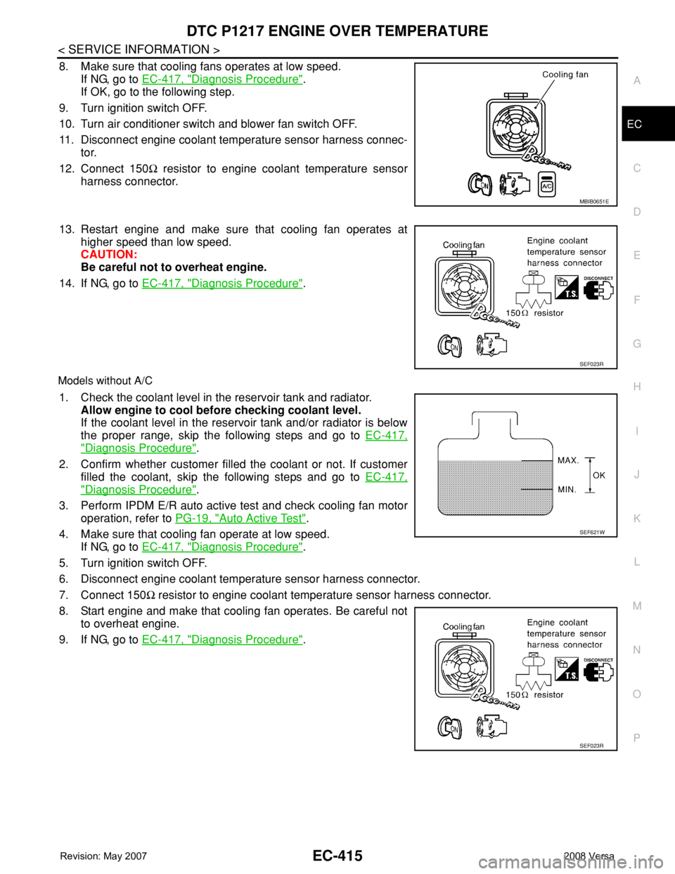
8. Make sure that cooling fans operates at low speed.
If NG, go to EC-417, "
Diagnosis Procedure".
If OK, go to the following step.
9. Turn ignition switch OFF.
10. Turn air conditioner switch and blower fan switch OFF.
11. Disconnect engine coolant temperature sensor harness connec-
tor.
12. Connect 150Ω resistor to engine coolant temperature sensor
harness connector.
13. Restart engine and make sure that cooling fan operates at
higher speed than low speed.
CAUTION:
Be careful not to overheat engine.
14. If NG, go to EC-417, "
Diagnosis Procedure".
Models without A/C
1. Check the coolant level in the reservoir tank and radiator.
Allow engine to cool before checking coolant level.
If the coolant level in the reservoir tank and/or radiator is below
the proper range, skip the following steps and go to EC-417,
"Diagnosis Procedure".
2. Confirm whether customer filled the coolant or not. If customer
filled the coolant, skip the following steps and go to EC-417,
"Diagnosis Procedure".
3. Perform IPDM E/R auto active test and check cooling fan motor
operation, refer to PG-19, "
Auto Active Test".
4. Make sure that cooling fan operate at low speed.
If NG, go to EC-417, "
Diagnosis Procedure".
5. Turn ignition switch OFF.
6. Disconnect engine coolant temperature sensor harness connector.
7. Connect 150Ω resistor to engine coolant temperature sensor harness connector.
8. Start engine and make that cooling fan operates. Be careful not
to overheat engine.
9. If NG, go to EC-417, "
Diagnosis Procedure".
MBIB0651E
SEF023R
SEF621W
SEF023R
Page 1492 of 2771

EC-418
< SERVICE INFORMATION >
DTC P1217 ENGINE OVER TEMPERATURE
No >> GO TO 4.
2.CHECK COOLING FAN LOW SPEED OPERATION
With CONSULT-II
1. Turn ignition switch ON.
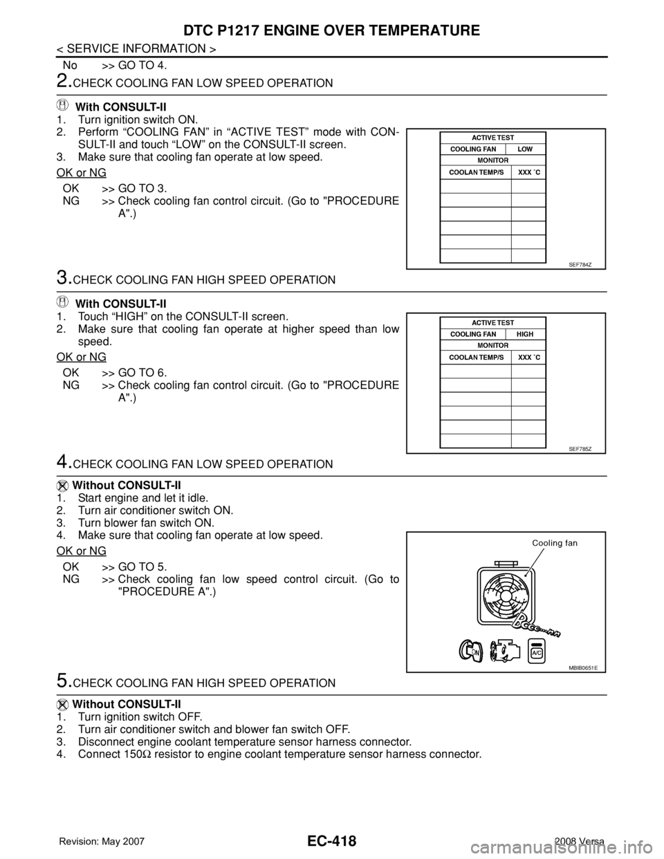
2. Perform “COOLING FAN” in “ACTIVE TEST” mode with CON-
SULT-II and touch “LOW” on the CONSULT-II screen.
3. Make sure that cooling fan operate at low speed.
OK or NG
OK >> GO TO 3.
NG >> Check cooling fan control circuit. (Go to "PROCEDURE
A".)
3.CHECK COOLING FAN HIGH SPEED OPERATION
With CONSULT-II
1. Touch “HIGH” on the CONSULT-II screen.
2. Make sure that cooling fan operate at higher speed than low
speed.
OK or NG
OK >> GO TO 6.
NG >> Check cooling fan control circuit. (Go to "PROCEDURE
A".)
4.CHECK COOLING FAN LOW SPEED OPERATION
Without CONSULT-II
1. Start engine and let it idle.
2. Turn air conditioner switch ON.
3. Turn blower fan switch ON.
4. Make sure that cooling fan operate at low speed.
OK or NG
OK >> GO TO 5.
NG >> Check cooling fan low speed control circuit. (Go to
"PROCEDURE A".)
5.CHECK COOLING FAN HIGH SPEED OPERATION
Without CONSULT-II
1. Turn ignition switch OFF.
2. Turn air conditioner switch and blower fan switch OFF.
3. Disconnect engine coolant temperature sensor harness connector.
4. Connect 150Ω resistor to engine coolant temperature sensor harness connector.
SEF784Z
SEF785Z
MBIB0651E
Page 1493 of 2771

DTC P1217 ENGINE OVER TEMPERATURE
EC-419
< SERVICE INFORMATION >
C
D
E
F
G
H
I
J
K
L
MA
EC
N
P O
5. Restart engine and make sure that cooling fan operate at higher
speed than low speed.
OK or NG
OK >> GO TO 6.
NG >> Check cooling fan high speed control circuit. (Go to
"PROCEDURE A".)
6.CHECK COOLING SYSTEM FOR LEAK
Refer to CO-8
.
OK or NG
OK >> GO TO 8.
NG >> GO TO 7.
7.DETECT MALFUNCTIONING PART
Check the following for leak.
•Hose
• Radiator
• Water pump (Refer to CO-16
.)
>> Repair or replace.
8.CHECK RADIATOR CAP
Refer to CO-11
.
OK or NG
OK >> GO TO 9.
NG >> Replace radiator cap.
9.CHECK COMPONENT PARTS
Check the following;.
• Thermostat. (Refer to CO-16
.)
• Water control valve. (Refer to CO-19
.)
• Engine coolant temperature sensor. (Refer to EC-191, "
Component Inspection".)
OK or NG
OK >> GO TO 10.
NG >> Replace malfunctioning component.
10.CHECK MAIN 13 CAUSES
If the cause cannot be isolated, go to EC-424, "
Main 13 Causes of Overheating".
>>INSPECTION END
PROCEDURE A
1.CHECK POWER SUPPLY CIRCUIT
1. Turn ignition switch OFF.
2. Disconnect IPDM E/R harness connector E44.
SEF023R
Page 1496 of 2771

EC-422
< SERVICE INFORMATION >
DTC P1217 ENGINE OVER TEMPERATURE
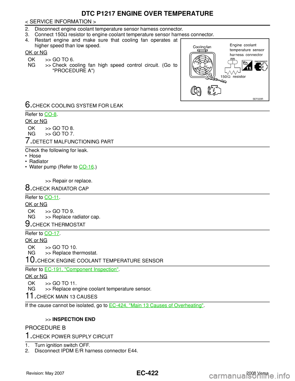
2. Disconnect engine coolant temperature sensor harness connector.
3. Connect 150Ω resistor to engine coolant temperature sensor harness connector.
4. Restart engine and make sure that cooling fan operates at
higher speed than low speed.
OK or NG
OK >> GO TO 6.
NG >> Check cooling fan high speed control circuit. (Go to
"PROCEDURE A")
6.CHECK COOLING SYSTEM FOR LEAK
Refer to CO-8
.
OK or NG
OK >> GO TO 8.
NG >> GO TO 7.
7.DETECT MALFUNCTIONING PART
Check the following for leak.
•Hose
• Radiator
• Water pump (Refer to CO-16
.)
>> Repair or replace.
8.CHECK RADIATOR CAP
Refer to CO-11
.
OK or NG
OK >> GO TO 9.
NG >> Replace radiator cap.
9.CHECK THERMOSTAT
Refer to CO-17
.
OK or NG
OK >> GO TO 10.
NG >> Replace thermostat.
10.CHECK ENGINE COOLANT TEMPERATURE SENSOR
Refer to EC-191, "
Component Inspection".
OK or NG
OK >> GO TO 11.
NG >> Replace engine coolant temperature sensor.
11 .CHECK MAIN 13 CAUSES
If the cause cannot be isolated, go to EC-424, "
Main 13 Causes of Overheating".
>>INSPECTION END
PROCEDURE B
1.CHECK POWER SUPPLY CIRCUIT
1. Turn ignition switch OFF.
2. Disconnect IPDM E/R harness connector E44.
SEF023R
Page 1622 of 2771

EC-548
< SERVICE INFORMATION >
SERVICE DATA AND SPECIFICATIONS (SDS)
SERVICE DATA AND SPECIFICATIONS (SDS)
Fuel PressureINFOID:0000000001703081
Idle Speed and Ignition TimingINFOID:0000000001703082
*: Under the following conditions:
• Air conditioner switch: OFF
• Electric load: OFF (Lights, heater fan & rear window defogger)
• Steering wheel: Kept in straight-ahead position
Calculated Load ValueINFOID:0000000001703083
Mass Air Flow SensorINFOID:0000000001703084
*: Engine is warmed up to normal operating temperature and running under no load.
Intake Air Temperature SensorINFOID:0000000001703085
Engine Coolant Temperature SensorINFOID:0000000001703086
Fuel pressure at idle
Approximately 350 kPa (3.57 kg/cm2, 51 psi)
Target idle speedA/T No load* (in P or N position)
700 ± 50 rpm CVT No load* (In P or N position)
M/T No load* (in Neutral position)
Air conditioner: ONA/T In P or N position
850 rpm or more CVT In P or N position
M/T In Neutral position
Ignition timingA/T In P or N position
13 ± 5° BTDC CVT In P or N position
M/T In Neutral position
Calculated load value% (Using CONSULT-II or GST)
At idle10 - 35
At 2,500 rpm10 - 35
Supply voltageBattery voltage (11 - 14V)
Output voltage at idle1.0 - 1.3*V
Mass air flow (Using CONSULT-II or GST)1.0 - 4.0 g·m/sec at idle*
2.0 - 10.0 g·m/sec at 2,500 rpm*
Temperature °C (°F) Resistance kΩ
25 (77)1.800 - 2.200
Temperature °C (°F) Resistance kΩ
20 (68)2.1 - 2.9
50 (122)0.68 - 1.00
90 (194)0.236 - 0.260
Page 1898 of 2771

TERMINOLOGY
GI-47
< SERVICE INFORMATION >
C
D
E
F
G
H
I
J
K
L
MB
GI
N
O
PTERMINOLOGY
SAE J1930 Terminology ListINFOID:0000000001702459
All emission related terms used in this publication in accordance with SAE J1930 are listed. Accordingly, new
terms, new acronyms/abbreviations and old terms are listed in the following chart.
NEW TERMNEW ACRONYM /
ABBREVIATIONOLD TERM
Air cleaner ACL Air cleaner
Barometric pressure BARO ***
Barometric pressure sensor-BCDD BAROS-BCDD BCDD
Camshaft position CMP ***
Camshaft position sensor CMPS Crank angle sensor
Canister *** Canister
Carburetor CARB Carburetor
Charge air cooler CAC Intercooler
Closed loop CL Closed loop
Closed throttle position switch CTP switch Idle switch
Clutch pedal position switch CPP switch Clutch switch
Continuous fuel injection system CFI system ***
Continuous trap oxidizer system CTOX system ***
Crankshaft position CKP ***
Crankshaft position sensor CKPS ***
Data link connector DLC ***
Data link connector for CONSULT-III DLC for CONSULT-III Diagnostic connector for CONSULT-III
Diagnostic test mode DTM Diagnostic mode
Diagnostic test mode selector DTM selector Diagnostic mode selector
Diagnostic test mode I DTM I Mode I
Diagnostic test mode II DTM II Mode II
Diagnostic trouble code DTC Malfunction code
Direct fuel injection system DFI system ***
Distributor ignition system DI system Ignition timing control
Early fuel evaporation-mixture heater EFE-mixture heater Mixture heater
Early fuel evaporation system EFE system Mixture heater control
Electrically erasable programmable read
only memoryEEPROM ***
Electronic ignition system EI system Ignition timing control
Engine control EC ***
Engine control module ECM ECCS control unit
Engine coolant temperature ECT Engine temperature
Engine coolant temperature sensor ECTS Engine temperature sensor
Engine modification EM ***
Engine speed RPM Engine speed
Erasable programmable read only memory EPROM ***
Evaporative emission canister EVAP canister Canister
Evaporative emission system EVAP system Canister control solenoid valve
Exhaust gas recirculation valve EGR valve EGR valve
Page 2015 of 2771
![NISSAN TIIDA 2008 Service Repair Manual LAN-24
< FUNCTION DIAGNOSIS >[CAN]
CAN COMMUNICATION SYSTEM
Engine coolant temperature signal T R
Engine speed signal T R R
Engine status signal T R
Fuel consumption monitor signal T R
Malfunction ind NISSAN TIIDA 2008 Service Repair Manual LAN-24
< FUNCTION DIAGNOSIS >[CAN]
CAN COMMUNICATION SYSTEM
Engine coolant temperature signal T R
Engine speed signal T R R
Engine status signal T R
Fuel consumption monitor signal T R
Malfunction ind](/manual-img/5/57399/w960_57399-2014.png)
LAN-24
< FUNCTION DIAGNOSIS >[CAN]
CAN COMMUNICATION SYSTEM
Engine coolant temperature signal T R
Engine speed signal T R R
Engine status signal T R
Fuel consumption monitor signal T R
Malfunction indicator lamp signal T R
Wide open throttle position signal T R R
A/C switch signal R T
Blower fan motor switch signal R T
Buzzer output signalTR
TR
Day time running light request signal
*3TR R
Door lock/unlock status signal T R
Door switch signal T R R R
Front wiper request signal T R
High beam request signal T R R
Horn chirp signal T R
Ignition switch signal T R
Low beam request signal T R
Position lights request signal T R R
Rear window defogger switch signal T R
Sleep/wake up signalRT
TRR R
Theft warning horn request signal T R
Tire pressure signal
*4TR
Trunk open/close status signal T R
Turn indicator signal T R
EPS operation signal R T
EPS warning lamp signal T R
Door lock/unlock/trunk open request signal R T
Hazard request signal R T
Ignition knob switch signal R T
KEY warning lamp signal T R
LOCK warning lamp signal T R
Panic alarm request signal R T
Fuel level sensor signal R T
Overdrive control switch signal T R R
P/N range signal T R
Stop lamp switch signal T R R
Vehicle speed signalRRR T
RRRT R
R
*5R*5T*5
ABS warning lamp signal R TSignal name/Connecting unit
ECM
BCM
EPS
I-KEY
M&A
ABS
TCM
*1
TCM
*2
IPDM-E
Page 2391 of 2771

TROUBLE DIAGNOSIS
MTC-53
< SERVICE INFORMATION >
C
D
E
F
G
H
I
K
L
MA
B
MTC
N
O
P
NO >> Adjust or replace air mix door cable. Refer to MTC-64, "Air Mix Door Cable Adjustment" .
6.CHECK AIR DUCTS
Check ducts for air leaks.
OK or NG
OK >> GO TO 7.
NG >> Repair air leaks.
7.CHECK HEATER HOSE TEMPERATURES
1. Start engine and warm it up to normal operating temperature.
2. Touch both the inlet and outlet heater hoses.
Is the inlet hose hot and the outlet hose warm?
YES >> GO TO 8.
NO >> Both hoses warm: GO TO 9.
8.CHECK ENGINE COOLANT TEMPERATURE SENSOR
Check engine control temperature sensor. Refer to EC-187
.
OK or NG
OK >> System OK.
NG >> Repair or replace as necessary. Retest.
9.CHECK HEATER HOSES
Check heater hoses for proper installation.
OK or NG
OK >> GO TO 10.
NG >> Repair /replace as necessary. Retest GO TO 7.
10.BACK FLUSH HEATER CORE
1. Back flush heater core.
2. Drain the water from the system.
3. Refill system with new engine coolant. Refer to CO-8, "
Changing Engine Coolant" .
4. Start engine and warm it up to normal operating temperature.
5. Touch both the inlet and outlet heater hoses.
Is the inlet hose hot and the outlet hose warm? YES or NO
YES >> System OK.
NO >> Replace heater core and refill engine coolant. Refer to MTC-67
.
NoiseINFOID:0000000001704308
SYMPTOM: Noise
INSPECTION FLOW