2008 NISSAN TIIDA diagnostic
[x] Cancel search: diagnosticPage 1195 of 2771
TROUBLE DIAGNOSIS
EC-121
< SERVICE INFORMATION >
C
D
E
F
G
H
I
J
K
L
MA
EC
N
P O
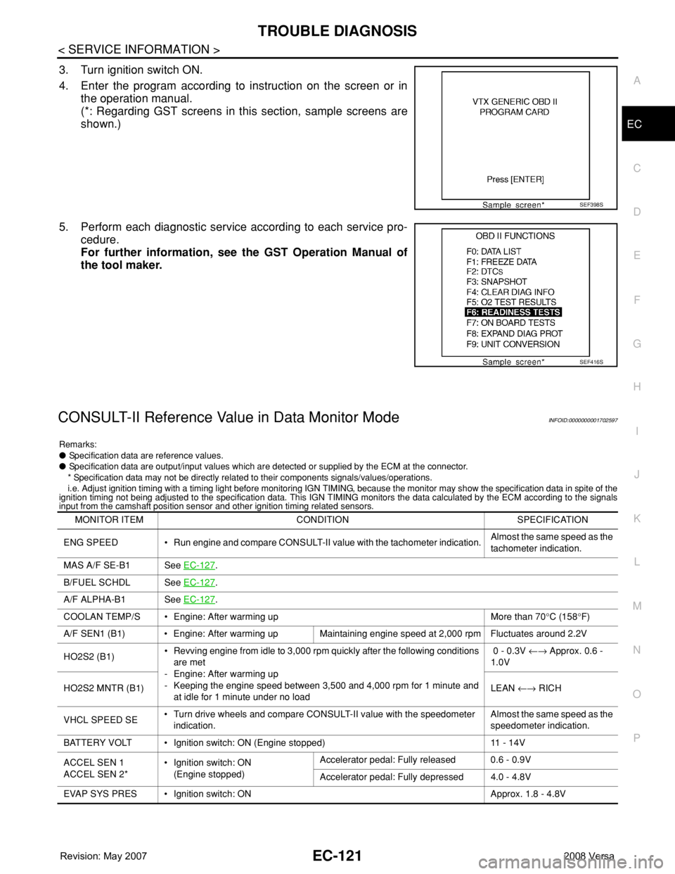
3. Turn ignition switch ON.
4. Enter the program according to instruction on the screen or in
the operation manual.
(*: Regarding GST screens in this section, sample screens are
shown.)
5. Perform each diagnostic service according to each service pro-
cedure.
For further information, see the GST Operation Manual of
the tool maker.
CONSULT-II Reference Value in Data Monitor ModeINFOID:0000000001702597
Remarks:
● Specification data are reference values.
● Specification data are output/input values which are detected or supplied by the ECM at the connector.
* Specification data may not be directly related to their components signals/values/operations.
i.e. Adjust ignition timing with a timing light before monitoring IGN TIMING, because the monitor may show the specification data in spite of the
ignition timing not being adjusted to the specification data. This IGN TIMING monitors the data calculated by the ECM according to the signals
input from the camshaft position sensor and other ignition timing related sensors.
SEF398S
SEF416S
MONITOR ITEM CONDITION SPECIFICATION
ENG SPEED • Run engine and compare CONSULT-II value with the tachometer indication.Almost the same speed as the
tachometer indication.
MAS A/F SE-B1 See EC-127
.
B/FUEL SCHDL See EC-127
.
A/F ALPHA-B1 See EC-127
.
COOLAN TEMP/S • Engine: After warming up More than 70°C (158°F)
A/F SEN1 (B1) • Engine: After warming up Maintaining engine speed at 2,000 rpm Fluctuates around 2.2V
HO2S2 (B1)• Revving engine from idle to 3,000 rpm quickly after the following conditions
are met
- Engine: After warming up
- Keeping the engine speed between 3,500 and 4,000 rpm for 1 minute and
at idle for 1 minute under no load 0 - 0.3V ←→ Approx. 0.6 -
1.0V
HO2S2 MNTR (B1)LEAN ←→ RICH
VHCL SPEED SE• Turn drive wheels and compare CONSULT-II value with the speedometer
indication.Almost the same speed as the
speedometer indication.
BATTERY VOLT • Ignition switch: ON (Engine stopped) 11 - 14V
ACCEL SEN 1
ACCEL SEN 2*• Ignition switch: ON
(Engine stopped)Accelerator pedal: Fully released 0.6 - 0.9V
Accelerator pedal: Fully depressed 4.0 - 4.8V
EVAP SYS PRES • Ignition switch: ON Approx. 1.8 - 4.8V
Page 1206 of 2771
EC-132
< SERVICE INFORMATION >
TROUBLE DIAGNOSIS - SPECIFICATION VALUE
12.CHECK A/F SENSOR 1 FUNCTION
Perform all DTC Confirmation Procedure related with A/F sensor 1.
• For DTC P0130, refer to EC-206, "
DTC Confirmation Procedure".
• For DTC P0131, refer to EC-213, "
DTC Confirmation Procedure".
• For DTC P0132, refer to EC-219, "
DTC Confirmation Procedure".
• For DTC P0133, refer to EC-225, "
DTC Confirmation Procedure".
• For DTC P2A00, refer to EC-500, "
DTC Confirmation Procedure".
OK or NG
OK >> GO TO 15.
NG >> GO TO 13.
13.CHECK A/F SENSOR 1 CIRCUIT
Perform Diagnostic Procedure according to corresponding DTC.
>> GO TO 14.
14.CHECK “A/F ALPHA-B1”
1. Start engine.
2. Select “A/F ALPHA-B1” in “DATA MONITOR (SPEC)” mode, and make sure that the indication is within
the SP value.
OK or NG
OK >>INSPECTION END
NG >> GO TO 15.
15.DISCONNECT AND RECONNECT ECM HARNESS CONNECTOR
1. Stop the engine.
2. Disconnect ECM harness connector. Check pin terminal and connector for damage, and then reconnect it.
>> GO TO 16.
16.CHECK “A/F ALPHA-B1”
1. Start engine.
2. Select “A/F ALPHA-B1” in “DATA MONITOR (SPEC)” mode, and make sure that the indication is within
the SP value.
OK or NG
OK >>INSPECTION END
NG >> Detect malfunctioning part according to EC-88, "
Symptom Matrix Chart".
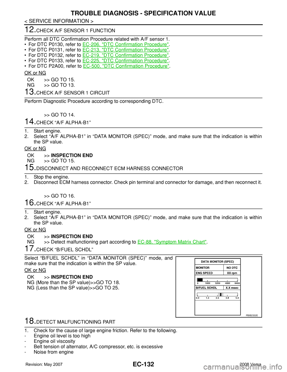
17.CHECK “B/FUEL SCHDL”
Select “B/FUEL SCHDL” in “DATA MONITOR (SPEC)” mode, and
make sure that the indication is within the SP value.
OK or NG
OK >>INSPECTION END
NG (More than the SP value)>>GO TO 18.
NG (Less than the SP value)>>GO TO 25.
18.DETECT MALFUNCTIONING PART
1. Check for the cause of large engine friction. Refer to the following.
- Engine oil level is too high
- Engine oil viscosity
- Belt tension of alternator, A/C compressor, etc. is excessive
- Noise from engine
PBIB2332E
Page 1210 of 2771
EC-136
< SERVICE INFORMATION >
TROUBLE DIAGNOSIS FOR INTERMITTENT INCIDENT
TROUBLE DIAGNOSIS FOR INTERMITTENT INCIDENT
DescriptionINFOID:0000000001702603
Intermittent incidents may occur. In many cases, the malfunction resolves itself (the part or circuit function
returns to normal without intervention). It is important to realize that the symptoms described in the customer's
complaint often do not recur on (1st trip) DTC visits. Realize also that the most frequent cause of Intermittent
Incidents occurrences is poor electrical connections. Because of this, the conditions under which the incident
occurred may not be clear. Therefore, circuit checks made as part of the standard diagnostic procedure may
not indicate the specific malfunctioning area.
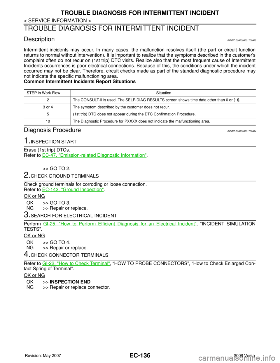
Common Intermittent Incidents Report Situations
Diagnosis ProcedureINFOID:0000000001702604
1.INSPECTION START
Erase (1st trip) DTCs.
Refer to EC-47, "
Emission-related Diagnostic Information".
>> GO TO 2.
2.CHECK GROUND TERMINALS
Check ground terminals for corroding or loose connection.
Refer to EC-142, "
Ground Inspection".
OK or NG
OK >> GO TO 3.
NG >> Repair or replace.
3.SEARCH FOR ELECTRICAL INCIDENT
Perform GI-25, "
How to Perform Efficient Diagnosis for an Electrical Incident", “INCIDENT SIMULATION
TESTS”.
OK or NG
OK >> GO TO 4.
NG >> Repair or replace.
4.CHECK CONNECTOR TERMINALS
Refer to GI-22, "
How to Check Terminal", “HOW TO PROBE CONNECTORS”, “How to Check Enlarged Con-
tact Spring of Terminal”.
OK or NG
OK >>INSPECTION END
NG >> Repair or replace connector.
STEP in Work Flow Situation
2 The CONSULT-II is used. The SELF-DIAG RESULTS screen shows time data other than 0 or [1t].
3 or 4 The symptom described by the customer does not recur.
5 (1st trip) DTC does not appear during the DTC Confirmation Procedure.
10 The Diagnostic Procedure for PXXXX does not indicate the malfunctioning area.
Page 1304 of 2771
EC-230
< SERVICE INFORMATION >
DTC P0133 A/F SENSOR 1
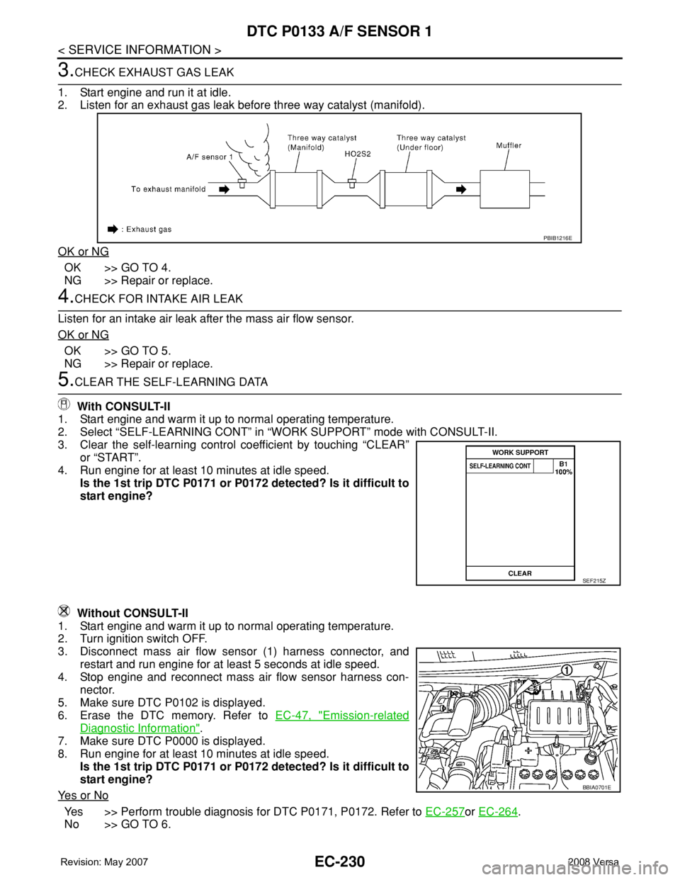
3.CHECK EXHAUST GAS LEAK
1. Start engine and run it at idle.
2. Listen for an exhaust gas leak before three way catalyst (manifold).
OK or NG
OK >> GO TO 4.
NG >> Repair or replace.
4.CHECK FOR INTAKE AIR LEAK
Listen for an intake air leak after the mass air flow sensor.
OK or NG
OK >> GO TO 5.
NG >> Repair or replace.
5.CLEAR THE SELF-LEARNING DATA
With CONSULT-II
1. Start engine and warm it up to normal operating temperature.
2. Select “SELF-LEARNING CONT” in “WORK SUPPORT” mode with CONSULT-II.
3. Clear the self-learning control coefficient by touching “CLEAR”
or “START”.
4. Run engine for at least 10 minutes at idle speed.
Is the 1st trip DTC P0171 or P0172 detected? Is it difficult to
start engine?
Without CONSULT-II
1. Start engine and warm it up to normal operating temperature.
2. Turn ignition switch OFF.
3. Disconnect mass air flow sensor (1) harness connector, and
restart and run engine for at least 5 seconds at idle speed.
4. Stop engine and reconnect mass air flow sensor harness con-
nector.
5. Make sure DTC P0102 is displayed.
6. Erase the DTC memory. Refer to EC-47, "
Emission-related
Diagnostic Information".
7. Make sure DTC P0000 is displayed.
8. Run engine for at least 10 minutes at idle speed.
Is the 1st trip DTC P0171 or P0172 detected? Is it difficult to
start engine?
Ye s o r N o
Yes >> Perform trouble diagnosis for DTC P0171, P0172. Refer to EC-257or EC-264.
No >> GO TO 6.
PBIB1216E
SEF215Z
BBIA0701E
Page 1311 of 2771
DTC P0137 HO2S2
EC-237
< SERVICE INFORMATION >
C
D
E
F
G
H
I
J
K
L
MA
EC
N
P O
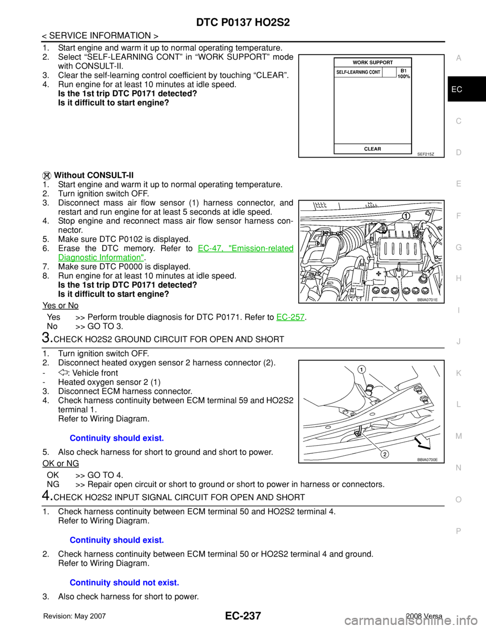
1. Start engine and warm it up to normal operating temperature.
2. Select “SELF-LEARNING CONT” in “WORK SUPPORT” mode
with CONSULT-II.
3. Clear the self-learning control coefficient by touching “CLEAR”.
4. Run engine for at least 10 minutes at idle speed.
Is the 1st trip DTC P0171 detected?
Is it difficult to start engine?
Without CONSULT-II
1. Start engine and warm it up to normal operating temperature.
2. Turn ignition switch OFF.
3. Disconnect mass air flow sensor (1) harness connector, and
restart and run engine for at least 5 seconds at idle speed.
4. Stop engine and reconnect mass air flow sensor harness con-
nector.
5. Make sure DTC P0102 is displayed.
6. Erase the DTC memory. Refer to EC-47, "
Emission-related
Diagnostic Information".
7. Make sure DTC P0000 is displayed.
8. Run engine for at least 10 minutes at idle speed.
Is the 1st trip DTC P0171 detected?
Is it difficult to start engine?
Ye s o r N o
Yes >> Perform trouble diagnosis for DTC P0171. Refer to EC-257.
No >> GO TO 3.
3.CHECK HO2S2 GROUND CIRCUIT FOR OPEN AND SHORT
1. Turn ignition switch OFF.
2. Disconnect heated oxygen sensor 2 harness connector (2).
- : Vehicle front
- Heated oxygen sensor 2 (1)
3. Disconnect ECM harness connector.
4. Check harness continuity between ECM terminal 59 and HO2S2
terminal 1.
Refer to Wiring Diagram.
5. Also check harness for short to ground and short to power.
OK or NG
OK >> GO TO 4.
NG >> Repair open circuit or short to ground or short to power in harness or connectors.
4.CHECK HO2S2 INPUT SIGNAL CIRCUIT FOR OPEN AND SHORT
1. Check harness continuity between ECM terminal 50 and HO2S2 terminal 4.
Refer to Wiring Diagram.
2. Check harness continuity between ECM terminal 50 or HO2S2 terminal 4 and ground.
Refer to Wiring Diagram.
3. Also check harness for short to power.
SEF215Z
BBIA0701E
Continuity should exist.
BBIA0700E
Continuity should exist.
Continuity should not exist.
Page 1320 of 2771
EC-246
< SERVICE INFORMATION >
DTC P0138 HO2S2
OK or NG
OK >> GO TO 2.
NG >> Repair or replace ground connections.
2.CLEAR THE SELF-LEARNING DATA
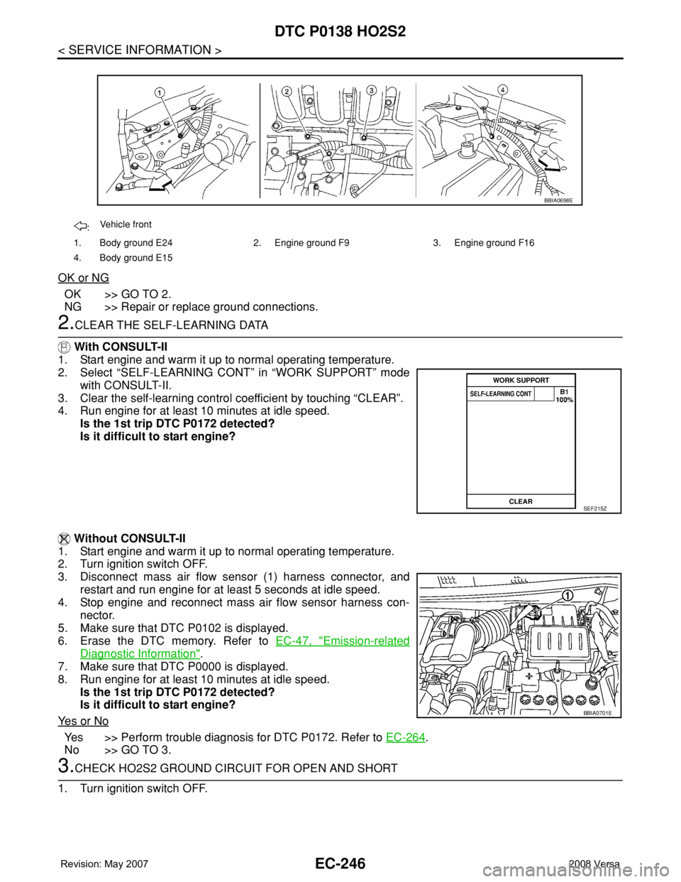
With CONSULT-II
1. Start engine and warm it up to normal operating temperature.
2. Select “SELF-LEARNING CONT” in “WORK SUPPORT” mode
with CONSULT-II.
3. Clear the self-learning control coefficient by touching “CLEAR”.
4. Run engine for at least 10 minutes at idle speed.
Is the 1st trip DTC P0172 detected?
Is it difficult to start engine?
Without CONSULT-II
1. Start engine and warm it up to normal operating temperature.
2. Turn ignition switch OFF.
3. Disconnect mass air flow sensor (1) harness connector, and
restart and run engine for at least 5 seconds at idle speed.
4. Stop engine and reconnect mass air flow sensor harness con-
nector.
5. Make sure that DTC P0102 is displayed.
6. Erase the DTC memory. Refer to EC-47, "
Emission-related
Diagnostic Information".
7. Make sure that DTC P0000 is displayed.
8. Run engine for at least 10 minutes at idle speed.
Is the 1st trip DTC P0172 detected?
Is it difficult to start engine?
Ye s o r N o
Yes >> Perform trouble diagnosis for DTC P0172. Refer to EC-264.
No >> GO TO 3.
3.CHECK HO2S2 GROUND CIRCUIT FOR OPEN AND SHORT
1. Turn ignition switch OFF.
:Vehicle front
1. Body ground E24 2. Engine ground F9 3. Engine ground F16
4. Body ground E15
BBIA0698E
SEF215Z
BBIA0701E
Page 1328 of 2771
EC-254
< SERVICE INFORMATION >
DTC P0139 HO2S2
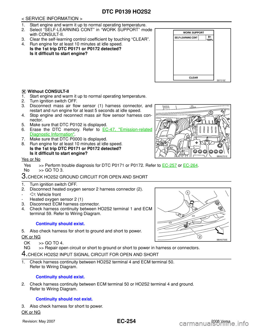
1. Start engine and warm it up to normal operating temperature.
2. Select “SELF-LEARNING CONT” in “WORK SUPPORT” mode
with CONSULT-II.
3. Clear the self-learning control coefficient by touching “CLEAR”.
4. Run engine for at least 10 minutes at idle speed.
Is the 1st trip DTC P0171 or P0172 detected?
Is it difficult to start engine?
Without CONSULT-II
1. Start engine and warm it up to normal operating temperature.
2. Turn ignition switch OFF.
3. Disconnect mass air flow sensor (1) harness connector, and
restart and run engine for at least 5 seconds at idle speed.
4. Stop engine and reconnect mass air flow sensor harness con-
nector.
5. Make sure that DTC P0102 is displayed.
6. Erase the DTC memory. Refer to EC-47, "
Emission-related
Diagnostic Information".
7. Make sure that DTC P0000 is displayed.
8. Run engine for at least 10 minutes at idle speed.
Is the 1st trip DTC P0171 or P0172 detected?
Is it difficult to start engine?
Ye s o r N o
Yes >> Perform trouble diagnosis for DTC P0171 or P0172. Refer to EC-257 or EC-264.
No >> GO TO 3.
3.CHECK HO2S2 GROUND CIRCUIT FOR OPEN AND SHORT
1. Turn ignition switch OFF.
2. Disconnect heated oxygen sensor 2 harness connector (2).
- : Vehicle front
- Heated oxygen sensor 2 (1)
3. Disconnect ECM harness connector.
4. Check harness continuity between HO2S2 terminal 1 and ECM
terminal 59. Refer to Wiring Diagram.
5. Also check harness for short to ground and short to power.
OK or NG
OK >> GO TO 4.
NG >> Repair open circuit or short to ground or short to power in harness or connectors.
4.CHECK HO2S2 INPUT SIGNAL CIRCUIT FOR OPEN AND SHORT
1. Check harness continuity between HO2S2 terminal 4 and ECM terminal 50.
Refer to Wiring Diagram.
2. Check harness continuity between ECM terminal 50 or HO2S2 terminal 4 and ground.
Refer to Wiring Diagram.
3. Also check harness for short to power.
OK or NG
SEF215Z
BBIA0701E
Continuity should exist.
BBIA0700E
Continuity should exist.
Continuity should not exist.
Page 1363 of 2771
DTC P0300 - P0304 MULTIPLE CYLINDER MISFIRE, NO. 1 - 4 CYLINDER MIS-
FIRE
EC-289
< SERVICE INFORMATION >
C
D
E
F
G
H
I
J
K
L
MA
EC
N
P O
6. Also check harness for short to power.
OK or NG
OK >> GO TO 14.
NG >> Repair open circuit or short to ground or short to power in harness or connectors.
14.CHECK AIR FUEL RATIO (A/F) SENSOR 1 HEATER
Refer to EC-154, "
Component Inspection".
OK or NG
OK >> GO TO 16.
NG >> GO TO 15.
15.REPLACE AIR FUEL RATIO (A/F) SENSOR 1
Replace air fuel ratio (A/F) sensor 1.
CAUTION:
• Discard any A/F sensor which has been dropped from a height of more than 0.5 m (19.7 in) onto a
hard surface such as a concrete floor; use a new one.
• Before installing new A/F sensor, clean exhaust system threads using Oxygen Sensor Thread
Cleaner tool J-43897-18 or J-43897-12 and approved anti-seize lubricant.
>>INSPECTION END
16.CHECK MASS AIR FLOW SENSOR
With CONSULT-II
1. Start engine and warm it up to normal operating temperature.
2. Check mass air flow sensor signal in “DATA MONITOR” mode with CONSULT-II.
With GST
1. Start engine and warm it up to normal operating temperature.
2. Check mass air flow sensor signal in Service $01 with GST.
OK or NG
OK >> GO TO 17.
NG >> Check connectors for rusted terminals or loose connections in the mass air flow sensor circuit or
ground. Refer to EC-167
.
17.CHECK SYMPTOM MATRIX CHART
Check items on the rough idle symptom in EC-88, "
Symptom Matrix Chart".
OK or NG
OK >> GO TO 18.
NG >> Repair or replace.
18.ERASE THE 1ST TRIP DTC
Some tests may cause a 1st trip DTC to be set.
Erase the 1st trip DTC from the ECM memory after performing the tests. Refer to EC-47, "
Emission-related
Diagnostic Information".
>> GO TO 19.
19.CHECK INTERMITTENT INCIDENT
Refer to EC-136
. Continuity should not exist.
at idling : 1.0 - 4.0 g·m/sec
at 2,500 rpm : 2.0 - 10.0 g·m/sec
at idling : 1.0 - 4.0 g·m/sec
at 2,500 rpm : 2.0 - 10.0 g·m/sec