Page 1690 of 2771
DRIVE BELTS
EM-13
< SERVICE INFORMATION >
C
D
E
F
G
H
I
J
K
L
MA
EM
N
P O
DRIVE BELTS
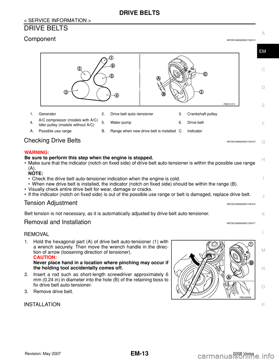
ComponentINFOID:0000000001702474
Checking Drive BeltsINFOID:0000000001702475
WARNING:
Be sure to perform this step when the engine is stopped.
• Make sure that the indicator (notch on fixed side) of drive belt auto-tensioner is within the possible use range
(A).
NOTE:
• Check the drive belt auto-tensioner indication when the engine is cold.
• When new drive belt is installed, the indicator (notch on fixed side) should be within the range (B).
• Visually check entire drive belt for wear, damage or cracks.
• If the indicator (notch on fixed side) is out of the possible use range or belt is damaged, replace drive belt.
Tension AdjustmentINFOID:0000000001702476
Belt tension is not necessary, as it is automatically adjusted by drive belt auto-tensioner.
Removal and InstallationINFOID:0000000001702477
REMOVAL
1. Hold the hexagonal part (A) of drive belt auto-tensioner (1) with
a wrench securely. Then move the wrench handle in the direc-
tion of arrow (loosening direction of tensioner).
CAUTION:
Never place hand in a location where pinching may occur if
the holding tool accidentally comes off.
2. Insert a rod such as short-length screwdriver approximately 6
mm (0.24 in) in diameter into the hole (B) of the retaining boss to
fix drive belt auto-tensioner.
3. Remove drive belt.
INSTALLATION
1. Generator 2. Drive belt auto–tensioner 3. Crankshaft pulley
4.A/C compressor (models with A/C)
Idler pulley (models without A/C)5. Water pump 6. Drive belt
A. Possible use range B. Range when new drive belt is installed C. Indicator
PBIC3137J
PBIC3936E
Page 1691 of 2771
EM-14
< SERVICE INFORMATION >
DRIVE BELTS
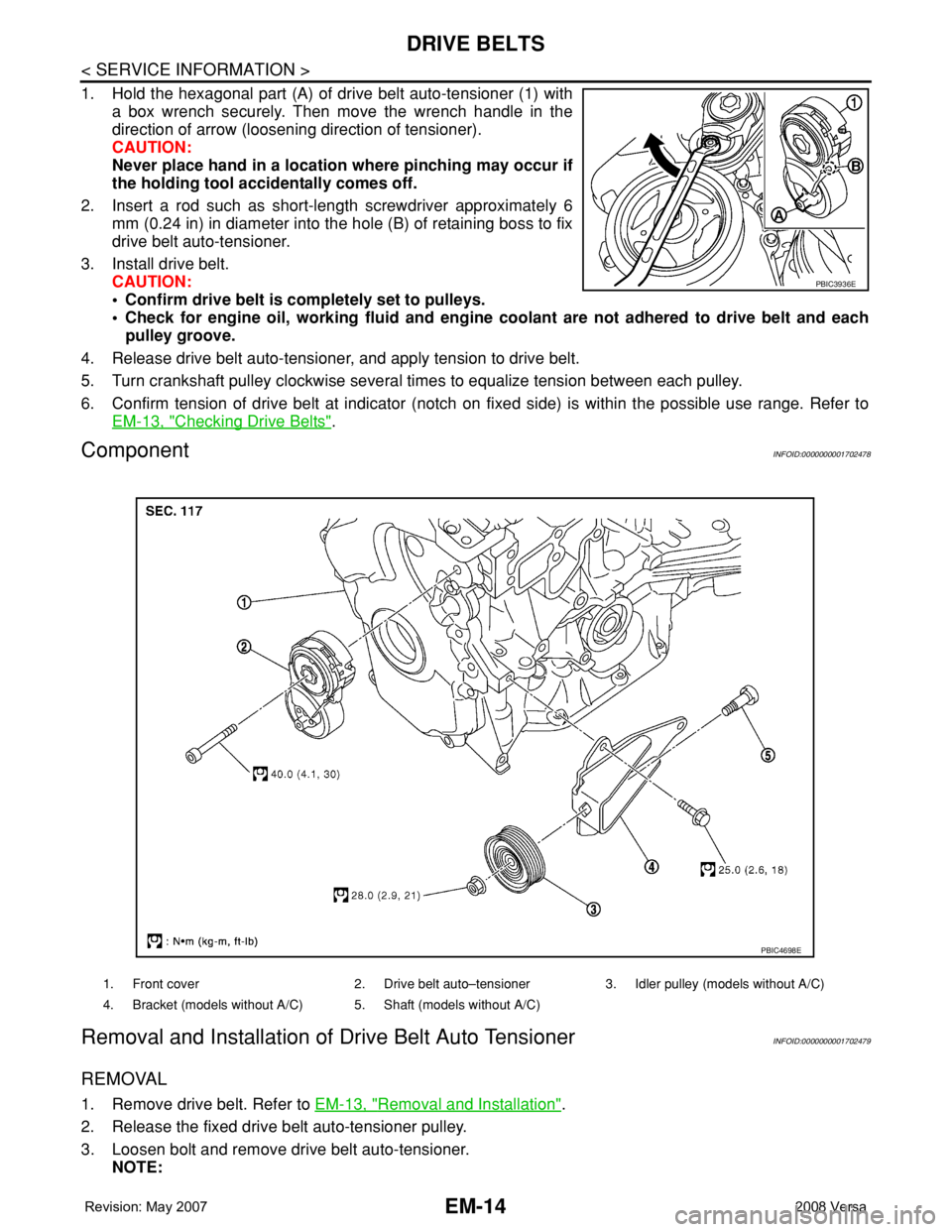
1. Hold the hexagonal part (A) of drive belt auto-tensioner (1) with
a box wrench securely. Then move the wrench handle in the
direction of arrow (loosening direction of tensioner).
CAUTION:
Never place hand in a location where pinching may occur if
the holding tool accidentally comes off.
2. Insert a rod such as short-length screwdriver approximately 6
mm (0.24 in) in diameter into the hole (B) of retaining boss to fix
drive belt auto-tensioner.
3. Install drive belt.
CAUTION:
• Confirm drive belt is completely set to pulleys.
• Check for engine oil, working fluid and engine coolant are not adhered to drive belt and each
pulley groove.
4. Release drive belt auto-tensioner, and apply tension to drive belt.
5. Turn crankshaft pulley clockwise several times to equalize tension between each pulley.
6. Confirm tension of drive belt at indicator (notch on fixed side) is within the possible use range. Refer to
EM-13, "
Checking Drive Belts".
ComponentINFOID:0000000001702478
Removal and Installation of Drive Belt Auto TensionerINFOID:0000000001702479
REMOVAL
1. Remove drive belt. Refer to EM-13, "Removal and Installation".
2. Release the fixed drive belt auto-tensioner pulley.
3. Loosen bolt and remove drive belt auto-tensioner.
NOTE:
PBIC3936E
1. Front cover 2. Drive belt auto–tensioner 3. Idler pulley (models without A/C)
4. Bracket (models without A/C) 5. Shaft (models without A/C)
PBIC4698E
Page 1694 of 2771
AIR CLEANER AND AIR DUCT
EM-17
< SERVICE INFORMATION >
C
D
E
F
G
H
I
J
K
L
MA
EM
N
P O
• Align marks.
• Attach each joint securely.
• Screw clamps firmly.
Changing Air Cleaner FilterINFOID:0000000001702482
REMOVAL
1. Push the tabs (A) of both ends of the air cleaner cover (1) into
the inside (B).
2. Pull up the air cleaner cover forward (C) and remove it.
3. Remove the air cleaner filter (1) and holder (2) assembly from
the air cleaner case.
4. Remove the air cleaner filter from the holder.
INSPECTION AFTER REMOVAL
It is necessary to replace it at the recommended intervals, more often under dusty driving conditions. Refer to
MA-6
.
INSTALLATION
Installation is in the reverse order of removal.
• Install the air cleaner cover (1) in the direction shown.
• Air cleaner filter (2)
• Holder (3)
PBIC3557J
PBIC3558J
PBIC3559J
Page 1713 of 2771
EM-36
< SERVICE INFORMATION >
FUEL INJECTOR AND FUEL TUBE
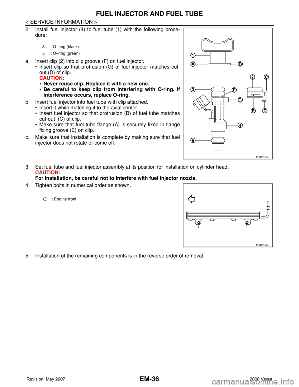
2. Install fuel injector (4) to fuel tube (1) with the following proce-
dure:
a. Insert clip (2) into clip groove (F) on fuel injector.
• Insert clip so that protrusion (G) of fuel injector matches cut-
out (D) of clip.
CAUTION:
• Never reuse clip. Replace it with a new one.
• Be careful to keep clip from interfering with O-ring. If
interference occurs, replace O-ring.
b. Insert fuel injector into fuel tube with clip attached.
• Insert it while matching it to the axial center.
• Insert fuel injector so that protrusion (B) of fuel tube matches
cut-out (C) of clip.
• Make sure that fuel tube flange (A) is securely fixed in flange
fixing groove (E) on clip.
c. Make sure that installation is complete by making sure that fuel
injector does not rotate or come off.
3. Set fuel tube and fuel injector assembly at its position for installation on cylinder head.
CAUTION:
For installation, be careful not to interfere with fuel injector nozzle.
4. Tighten bolts in numerical order as shown.
5. Installation of the remaining components is in the reverse order of removal.
3 : O–ring (black)
5 : O–ring (green)
PBIC3155J
: Engine front
PBIC3154J
Page 1718 of 2771
TIMING CHAIN
EM-41
< SERVICE INFORMATION >
C
D
E
F
G
H
I
J
K
L
MA
EM
N
P O
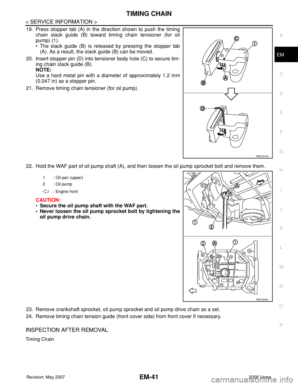
19. Press stopper tab (A) in the direction shown to push the timing
chain slack guide (B) toward timing chain tensioner (for oil
pump) (1).
• The slack guide (B) is released by pressing the stopper tab
(A). As a result, the slack guide (B) can be moved.
20. Insert stopper pin (D) into tensioner body hole (C) to secure tim-
ing chain slack guide (B).
NOTE:
Use a hard metal pin with a diameter of approximately 1.2 mm
(0.047 in) as a stopper pin.
21. Remove timing chain tensioner (for oil pump).
22. Hold the WAF part of oil pump shaft (A), and then loosen the oil pump sprocket bolt and remove them.
CAUTION:
• Secure the oil pump shaft with the WAF part.
• Never loosen the oil pump sprocket bolt by tightening the
oil pump drive chain.
23. Remove crankshaft sprocket, oil pump sprocket and oil pump drive chain as a set.
24. Remove timing chain tension guide (front cover side) from front cover if necessary.
INSPECTION AFTER REMOVAL
Timing Chain
PBIC5314E
1 : Oil pan (upper)
2: Oil pump
: Engine front
PBIC3539J
Page 1720 of 2771
TIMING CHAIN
EM-43
< SERVICE INFORMATION >
C
D
E
F
G
H
I
J
K
L
MA
EM
N
P O
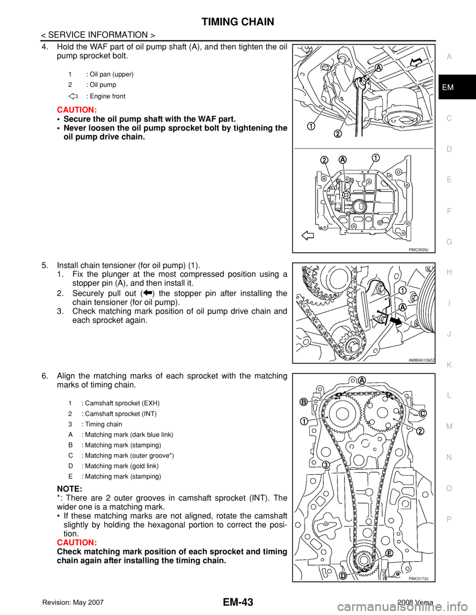
4. Hold the WAF part of oil pump shaft (A), and then tighten the oil
pump sprocket bolt.
CAUTION:
• Secure the oil pump shaft with the WAF part.
• Never loosen the oil pump sprocket bolt by tightening the
oil pump drive chain.
5. Install chain tensioner (for oil pump) (1).
1. Fix the plunger at the most compressed position using a
stopper pin (A), and then install it.
2. Securely pull out ( ) the stopper pin after installing the
chain tensioner (for oil pump).
3. Check matching mark position of oil pump drive chain and
each sprocket again.
6. Align the matching marks of each sprocket with the matching
marks of timing chain.
NOTE:
*: There are 2 outer grooves in camshaft sprocket (INT). The
wider one is a matching mark.
• If these matching marks are not aligned, rotate the camshaft
slightly by holding the hexagonal portion to correct the posi-
tion.
CAUTION:
Check matching mark position of each sprocket and timing
chain again after installing the timing chain.
1 : Oil pan (upper)
2 : Oil pump
: Engine front
PBIC3539J
AWBIA0139ZZ
1 : Camshaft sprocket (EXH)
2 : Camshaft sprocket (INT)
3: Timing chain
A : Matching mark (dark blue link)
B : Matching mark (stamping)
C : Matching mark (outer groove*)
D : Matching mark (gold link)
E : Matching mark (stamping)
PBIC3172J
Page 1721 of 2771
EM-44
< SERVICE INFORMATION >
TIMING CHAIN
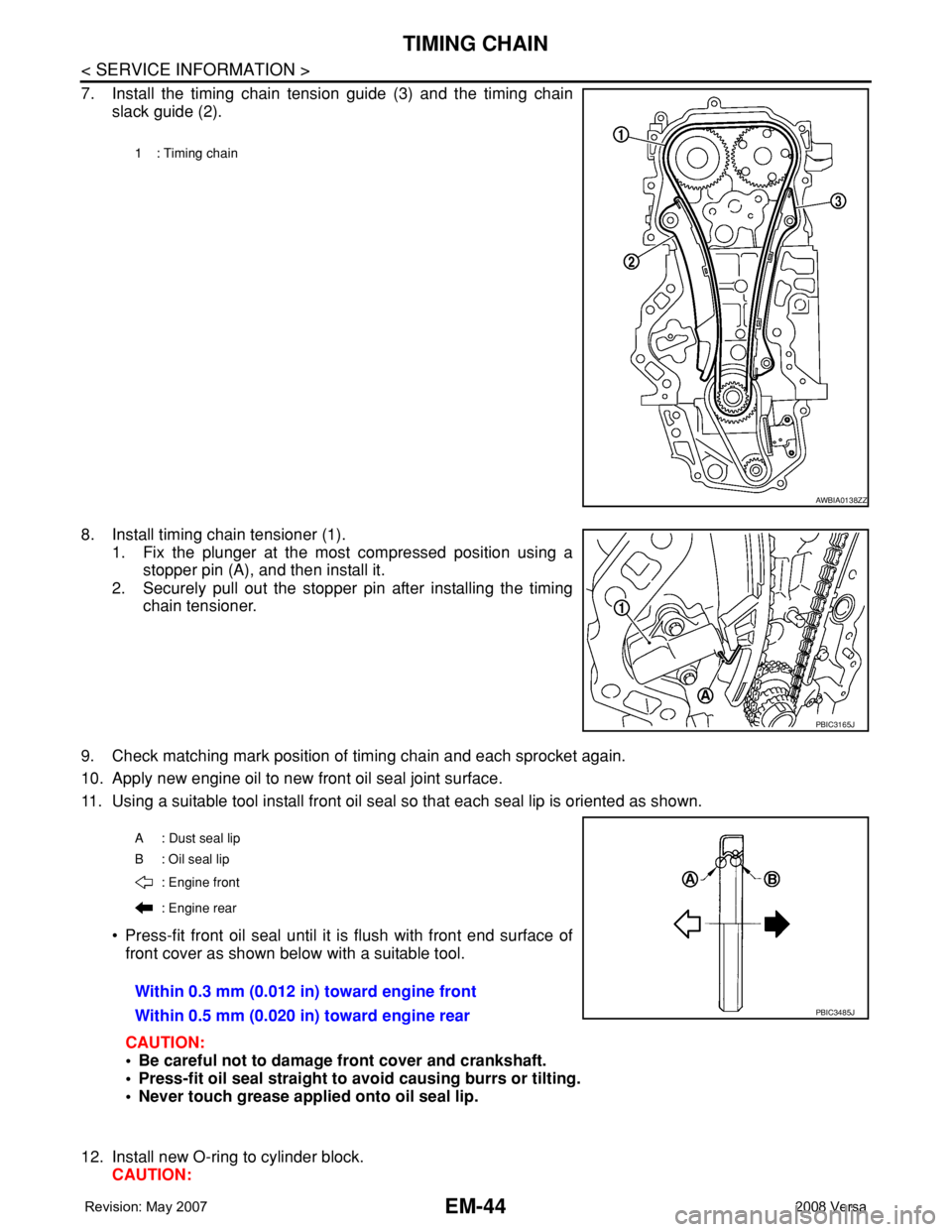
7. Install the timing chain tension guide (3) and the timing chain
slack guide (2).
8. Install timing chain tensioner (1).
1. Fix the plunger at the most compressed position using a
stopper pin (A), and then install it.
2. Securely pull out the stopper pin after installing the timing
chain tensioner.
9. Check matching mark position of timing chain and each sprocket again.
10. Apply new engine oil to new front oil seal joint surface.
11. Using a suitable tool install front oil seal so that each seal lip is oriented as shown.
• Press-fit front oil seal until it is flush with front end surface of
front cover as shown below with a suitable tool.
CAUTION:
• Be careful not to damage front cover and crankshaft.
• Press-fit oil seal straight to avoid causing burrs or tilting.
• Never touch grease applied onto oil seal lip.
12. Install new O-ring to cylinder block.
CAUTION:
1 : Timing chain
AWBIA0138ZZ
PBIC3165J
A : Dust seal lip
B: Oil seal lip
: Engine front
: Engine rear
Within 0.3 mm (0.012 in) toward engine front
Within 0.5 mm (0.020 in) toward engine rear
PBIC3485J
Page 1723 of 2771
EM-46
< SERVICE INFORMATION >
TIMING CHAIN
18. Secure crankshaft pulley (1) using Tool (A).
19. Apply new engine oil to thread and seat surfaces of crankshaft
pulley bolt.
20. Tighten crankshaft pulley bolt in three steps.
21. Put a paint mark (B) on crankshaft pulley (2), matching with any
one of six easy to recognize angle marks (A) on crankshaft pul-
ley bolt flange (1).
22. Turn another 60 degrees clockwise (angle tightening) using
Tool.
• Check the tightening angle with movement of one angle mark.
23. Make sure that crankshaft rotates clockwise smoothly.
24. Installation of the remaining components is in the reverse order of removal.Tool Number (A) : KV10109300 ( — )
Step 1 : 68.6 N·m (7.0 kg-m, 51 ft-lb)
Step 2 : 0 N·m (0 kg-m, 0 ft-lb)
Step 3 : 29.4 N·m (3.0 kg-m, 22 ft-lb)
PBIC3961E
Tool number : KV10112100 (BT-8653-A)
PBIC3963E