2008 NISSAN TIIDA check engine
[x] Cancel search: check enginePage 210 of 2771
AT-198
< SERVICE INFORMATION >
TROUBLE DIAGNOSIS FOR SYMPTOMS
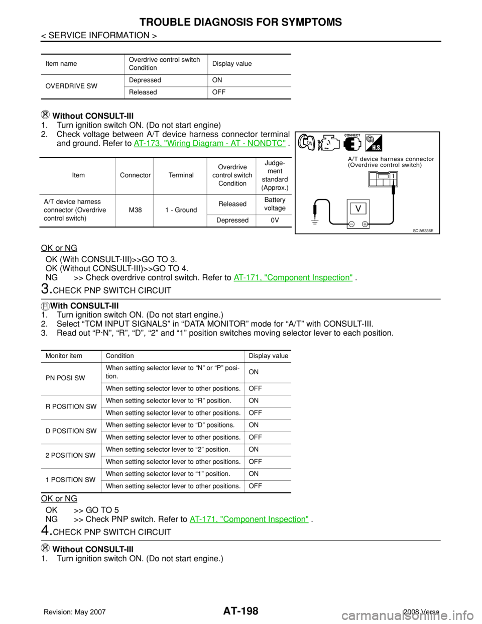
Without CONSULT-III
1. Turn ignition switch ON. (Do not start engine)
2. Check voltage between A/T device harness connector terminal
and ground. Refer to AT-173, "
Wiring Diagram - AT - NONDTC" .
OK or NG
OK (With CONSULT-III)>>GO TO 3.
OK (Without CONSULT-III)>>GO TO 4.
NG >> Check overdrive control switch. Refer to AT-171, "
Component Inspection" .
3.CHECK PNP SWITCH CIRCUIT
With CONSULT-III
1. Turn ignition switch ON. (Do not start engine.)
2. Select “TCM INPUT SIGNALS” in “DATA MONITOR” mode for “A/T” with CONSULT-III.
3. Read out “P·N”, “R”, “D”, “2” and “1” position switches moving selector lever to each position.
OK or NG
OK >> GO TO 5
NG >> Check PNP switch. Refer to AT-171, "
Component Inspection" .
4.CHECK PNP SWITCH CIRCUIT
Without CONSULT-III
1. Turn ignition switch ON. (Do not start engine.)
Item nameOverdrive control switch
ConditionDisplay value
OVERDRIVE SWDepressed ON
Released OFF
Item Connector TerminalOverdrive
control switch
ConditionJudge-
ment
standard
(Approx.)
A/T device harness
connector (Overdrive
control switch)M38 1 - GroundReleasedBattery
voltage
Depressed 0V
SCIA5336E
Monitor item Condition Display value
PN POSI SWWhen setting selector lever to “N” or “P” posi-
tion.ON
When setting selector lever to other positions. OFF
R POSITION SWWhen setting selector lever to “R” position. ON
When setting selector lever to other positions. OFF
D POSITION SWWhen setting selector lever to “D” positions. ON
When setting selector lever to other positions. OFF
2 POSITION SWWhen setting selector lever to “2” position. ON
When setting selector lever to other positions. OFF
1 POSITION SWWhen setting selector lever to “1” position. ON
When setting selector lever to other positions. OFF
Page 219 of 2771

SHIFT CONTROL SYSTEM
AT-207
< SERVICE INFORMATION >
D
E
F
G
H
I
J
K
L
MA
B
AT
N
O
P
1. Place the selector lever knob (1) in “N” position.
2. Slide knob cover (2) downward.
3. Pull out lock pin (3) from selector lever knob (1).
4. Remove selector lever knob (1) and knob cover (2) as a set from
selector lever.
CAUTION:
Do not push selector button.
INSTALLATION
1. Insert lock pin (1) to selector lever knob (2).
2. Install knob cover (3) to selector lever knob (2).
3. Place the selector lever in “N” position.
4. Install selector lever knob over selector lever until a click is felt.
CAUTION:
• Do not tilt selector lever knob when installing. Install it
straight, and do not tap or apply any shock to install it.
• Do not push selector button.
Adjustment of A/T PositionINFOID:0000000001703359
Move selector lever from “P” position to “1” position. You should be able to feel the detents in each position. If
the detents cannot be felt or if the position indicator is improperly aligned, the control cable needs adjustment.
CAUTION:
Make sure that parking brake is applied before adjustment.
1. Remove the air duct assembly. Refer to EM-16
.
2. Remove the control cable nut (A) and control cable (1) and
place the manual lever (2) in the "P' position.
3. Place selector lever in “P” position.
4. Hold control cable (1) at the end and pull it with a force of 9.8 N
(approximately 1 kg, 2.2 lb). Release the control cable and tem-
porarily tighten control cable nut (A).
5. Tighten control cable nut (A) to the specified torque.
CAUTION:
Secure manual lever when tightening nut.
6. Move selector lever from “P” to “1” position again. Make sure that selector lever moves smoothly.
7. Check A/T position. Refer to AT-207, "
Checking of A/T Position".
8. Install air duct assembly. Refer to EM-16
.
Checking of A/T PositionINFOID:0000000001703360
1. Place selector lever in “P” position, and turn ignition switch ON (Do not start engine).
2. Make sure selector lever can be shifted to other than “P” position when brake pedal is depressed. Also
make sure selector lever can be shifted from “P” position only when brake pedal is depressed.
3. Move selector lever and check for excessive effort, sticking, noise or rattle.
4. Confirm selector lever stops at each position with the feel of engagement when it is moved through all the
positions. Check whether or not the actual position selector lever is in matches the position shown by the
shift position indicator and the transaxle.
SCIA6971E
SCIA6972E
Control cable nut : Refer to AT-203, "Control De-
vice Removal and Installation".WCIA0635E
Page 223 of 2771

A/T SHIFT LOCK SYSTEM
AT-211
< SERVICE INFORMATION >
D
E
F
G
H
I
J
K
L
MA
B
AT
N
O
P
•Selector lever can be moved from “P” position with ignition key in ON position and brake pedal
released.
•Selector lever can be moved from “P” position when ignition switch is removed from key cylinder.
SYMPTOM 2:
•Ignition key cannot be removed when selector lever is set to “P” position.
•Ignition key can be removed when selector lever is set to any position except “P” position.
1.CHECK KEY INTERLOCK CABLE
Check key interlock cable for damage.
OK or NG
OK >> GO TO 2.
NG >> Repair key interlock cable. Refer to AT-213, "
Removal and Installation" .
2.CHECK A/T POSITION
Check A/T position. Refer to AT-207, "
Checking of A/T Position" .
OK or NG
OK >> GO TO 3.
NG >> Adjust control cable. Refer to AT-207, "
Adjustment of A/T Position" .
3.CHECK SHIFT LOCK SOLENOID AND PARK POSITION SWITCH
1. Turn ignition switch ON. (Do not start engine.)
2. Selector lever is set in “P” position.
3. Check operation sound.
OK or NG
OK >>INSPECTION END
NG >> GO TO 4.
4.CHECK POWER SOURCE
1. Turn ignition switch ON. (Do not start engine.)
2. Check voltage between A/T device harness connector terminal
5 and ground.
OK or NG
OK >> GO TO 7.
NG >> GO TO 5.
5.CHECK STOP LAMP SWITCH
1. Turn ignition switch OFF.
2. Disconnect stop lamp switch harness connector.
Condition Brake pedal Operation sound
When ignition switch is turned to ON position and selector lever is set in
“P” position.Depressed Yes
Released No
Voltage:
Brake pedal depressed: Battery voltage
Brake pedal released: 0V
SCIA7171E
Page 228 of 2771
AT-216
< SERVICE INFORMATION >
ON-VEHICLE SERVICE
ON-VEHICLE SERVICE
Control Valve Assembly and AccumulatorsINFOID:0000000001703366
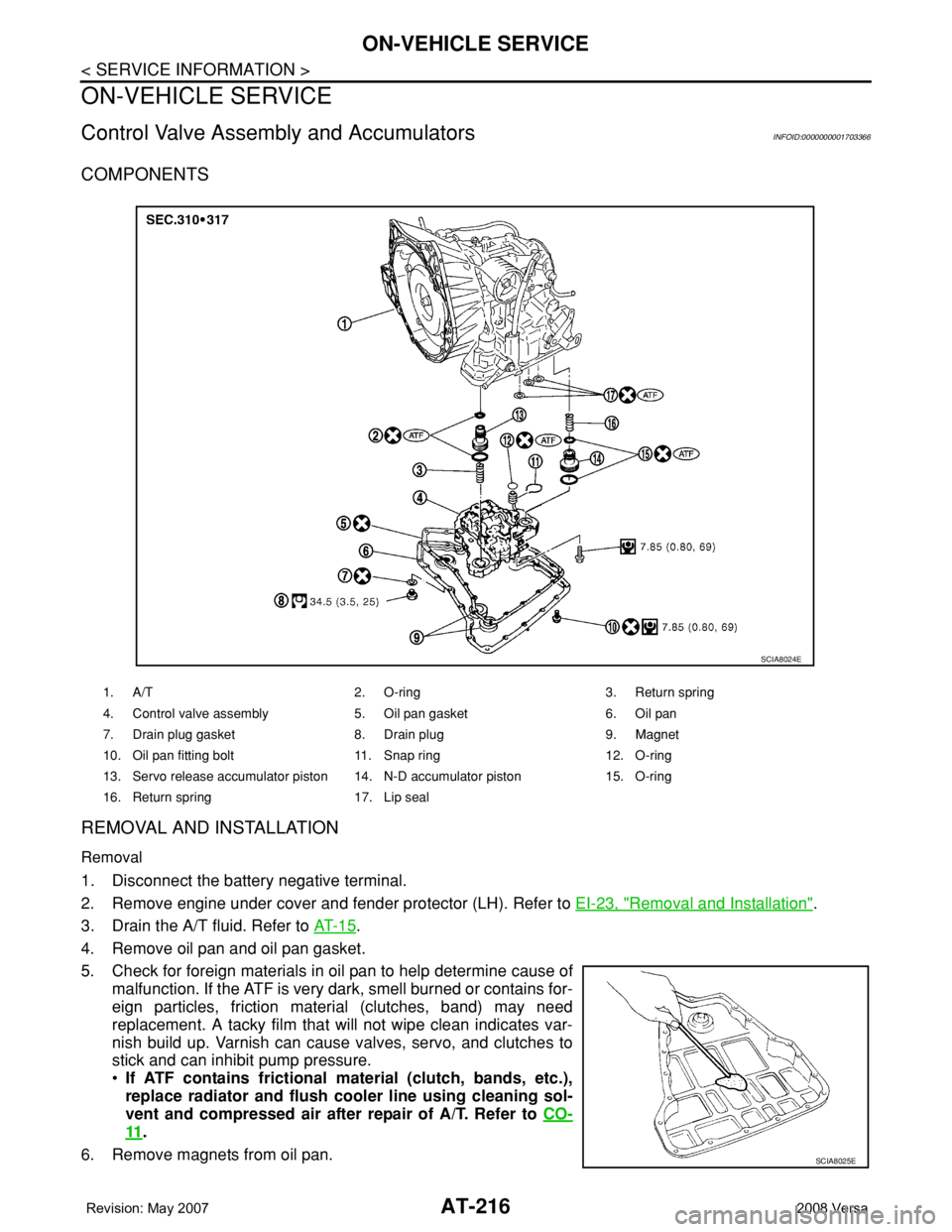
COMPONENTS
REMOVAL AND INSTALLATION
Removal
1. Disconnect the battery negative terminal.
2. Remove engine under cover and fender protector (LH). Refer to EI-23, "
Removal and Installation".
3. Drain the A/T fluid. Refer to AT- 1 5
.
4. Remove oil pan and oil pan gasket.
5. Check for foreign materials in oil pan to help determine cause of
malfunction. If the ATF is very dark, smell burned or contains for-
eign particles, friction material (clutches, band) may need
replacement. A tacky film that will not wipe clean indicates var-
nish build up. Varnish can cause valves, servo, and clutches to
stick and can inhibit pump pressure.
•If ATF contains frictional material (clutch, bands, etc.),
replace radiator and flush cooler line using cleaning sol-
vent and compressed air after repair of A/T. Refer to CO-
11.
6. Remove magnets from oil pan.
1. A/T 2. O-ring 3. Return spring
4. Control valve assembly 5. Oil pan gasket 6. Oil pan
7. Drain plug gasket 8. Drain plug 9. Magnet
10. Oil pan fitting bolt 11. Snap ring 12. O-ring
13. Servo release accumulator piston 14. N-D accumulator piston 15. O-ring
16. Return spring 17. Lip seal
SCIA8024E
SCIA8025E
Page 240 of 2771
AT-228
< SERVICE INFORMATION >
TRANSAXLE ASSEMBLY
• When replacing an engine or transmission you must make sure any dowels are installed correctly
during re-assembly.
• Improper alignment caused by missing dowels may cause vibration, oil leaks or breakage of drive
train components.
• Do not reuse O-rings and copper washers. Refer to "COMPONENTS".
• When turning crankshaft, turn it clockwise as viewed from the front of the engine.
• When tightening the bolts for the torque converter while securing the crankshaft pulley bolt, be sure
to confirm the tightening torque of the crankshaft pulley bolt. Refer to EM-37
.
• After converter is installed to drive plate, rotate crankshaft several turns to check that transaxle
rotates freely without binding.
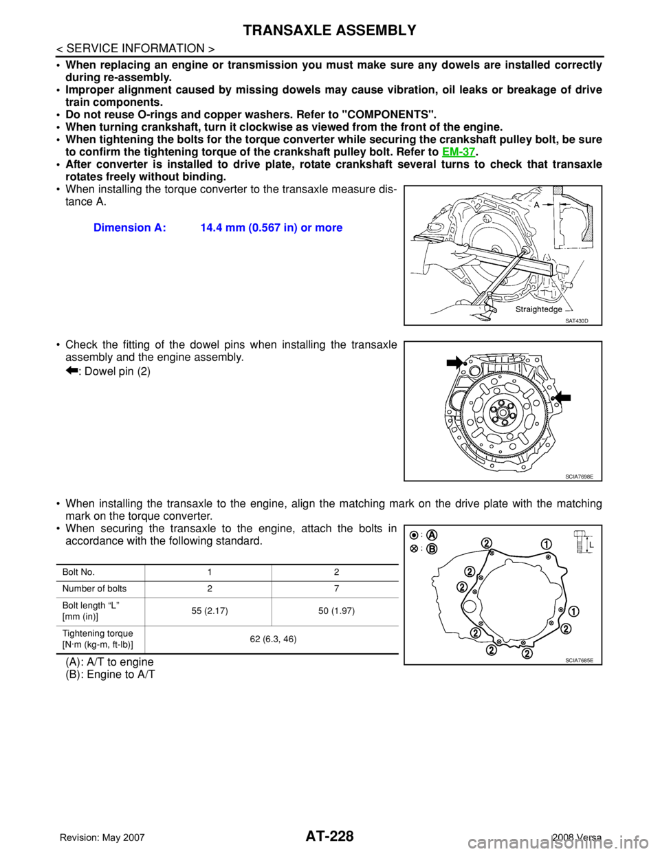
• When installing the torque converter to the transaxle measure dis-
tance A.
• Check the fitting of the dowel pins when installing the transaxle
assembly and the engine assembly.
: Dowel pin (2)
• When installing the transaxle to the engine, align the matching mark on the drive plate with the matching
mark on the torque converter.
• When securing the transaxle to the engine, attach the bolts in
accordance with the following standard.
(A): A/T to engine
(B): Engine to A/TDimension A: 14.4 mm (0.567 in) or more
SAT430D
SCIA7698E
Bolt No. 1 2
Number of bolts 2 7
Bolt length “L”
[mm (in)]55 (2.17) 50 (1.97)
Tightening torque
[N·m (kg-m, ft-lb)]62 (6.3, 46)
SCIA7685E
Page 380 of 2771
AUDIO
AV-21
< SERVICE INFORMATION >
C
D
E
F
G
H
I
J
L
MA
B
AV
N
O
P
and M45 first followed by M43 last. If the subwoofer is inoperative, be sure to check this condition. Refer to AV-
34, "Sound Is Not Heard from Subwoofer (Premium System)" .
• The majority of the audio malfunctions are the result of outside causes (damaged CD, electromagnetic inter-
ference, etc.). Check the symptoms below to diagnose the malfunction.
• The vehicle itself can be a source of noise if noise prevention parts or electrical equipment is malfunctioning.
Check if noise is caused and/or changed by engine speed, ignition switch turned to each position, and oper-
ation of each piece of electrical equipment, and then determine the cause.
NOTE:
Noise resulting from variations in field strength, such as fading noise and multi-path noise, or external noise
from trains and other sources. It is not a malfunction.
• Fading noise: This noise occurs because of variations in the field strength in a narrow range due to moun-
tains or buildings blocking the signal.
• Multi-path noise: This noise results from the waves sent directly from the broadcast station arriving at the
antenna at a different time from the waves that reflect off of mountains or buildings.
Noise InspectionINFOID:0000000001704662
The vehicle itself can be a source of noise if noise prevention parts or electrical equipment is malfunctioning.
Check if noise is caused and/or changed by engine speed, ignition switch turned to each position, and opera-
tion of each piece of electrical equipment, and determine the cause.
NOTE:
The source of the noise can be found easily by listening to the noise while removing the fuses of electrical
components, one by one.
TYPE OF NOISE AND POSSIBLE CAUSE
Symptom Check item
Audio system does not work properly.• Audio unit power supply circuit. Refer to AV- 2 2 , "
Power Supply
Circuit Inspection" .
• Audio unit. Refer to "Trouble Diagnosis" .
No sound can be heard from all speakers. Audio unit. Refer to "Trouble Diagnosis" .
No sound can be heard from one or several speakers.• Open or short in audio signal circuit between audio unit and front
speaker. Refer to AV- 2 9 , "
Sound Is Not Heard from Front Door
Speaker (Base System)" or AV- 3 1 , "Sound Is Not Heard from
Front Door Speaker or Tweeter (Mid Level and Premium Sys-
tem)" .
• Front speaker. Refer to AV- 2 9 , "
Sound Is Not Heard from Front
Door Speaker (Base System)" or AV- 3 1 , "Sound Is Not Heard
from Front Door Speaker or Tweeter (Mid Level and Premium
System)" .
• Open or short in audio signal circuit between audio unit and rear
speaker. Refer to AV- 3 0 , "
Sound Is Not Heard from Rear Door
Speaker (Base System)" or AV- 3 2 , "Sound Is Not Heard from
Rear Door Speaker (Mid Level and Premium System)" .
• Rear speaker. Refer to AV- 3 0 , "
Sound Is Not Heard from Rear
Door Speaker (Base System)" or AV- 3 2 , "Sound Is Not Heard
from Rear Door Speaker (Mid Level and Premium System)" .
• Tweeter (mid level and premium system) AV- 3 1 , "
Sound Is Not
Heard from Front Door Speaker or Tweeter (Mid Level and Pre-
mium System)" or AV- 3 2 , "Sound Is Not Heard from Rear Door
Speaker (Mid Level and Premium System)" .
• Subwoofer (premium system). Refer to AV- 3 4 , "
Sound Is Not
Heard from Subwoofer (Premium System)" .
• Audio unit. Refer to AV- 2 2 , "
Power Supply Circuit Inspection" .
No sound can be heard from radio or noise is heard.• Antenna feeder. Refer to AV- 4 1
.
• Antenna. Refer to AV- 4 1
.
• Audio unit. Refer to AV- 2 2 , "
Power Supply Circuit Inspection" .
Page 381 of 2771
AV-22
< SERVICE INFORMATION >
AUDIO
Power Supply Circuit Inspection
INFOID:0000000001704663
1.CHECK FUSE
Check that the following fuses of the subwoofer (premium system) and audio unit are not blown.
OK or NG
OK >> GO TO 2.
NG >> If fuse is blown, be sure to eliminate cause of blown fuse before installing new fuse. Refer to PG-
3 .
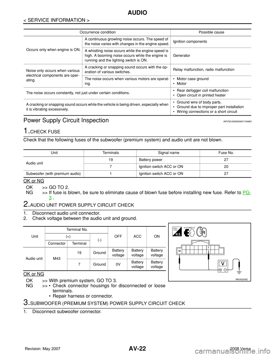
2.AUDIO UNIT POWER SUPPLY CIRCUIT CHECK
1. Disconnect audio unit connector.
2. Check voltage between the audio unit and ground.
OK or NG
OK >> With premium system, GO TO 3.
NG >> • Check connector housings for disconnected or loose
terminals.
• Repair harness or connector.
3.SUBWOOFER (PREMIUM SYSTEM) POWER SUPPLY CIRCUIT CHECK
1. Disconnect subwoofer connector.
Occurrence condition Possible cause
Occurs only when engine is ON.A continuous growling noise occurs. The speed of
the noise varies with changes in the engine speed.Ignition components
A whistling noise occurs while the engine speed is
high. A booming noise occurs while the engine is
running and the lighting switch is ON.Generator
Noise only occurs when various
electrical components are oper-
ating.A cracking or snapping sound occurs with the op-
eration of various switches.Relay malfunction, radio malfunction
The noise occurs when various motors are operat-
ing.• Motor case ground
• Motor
The noise occurs constantly, not just under certain conditions.• Rear defogger coil malfunction
• Open circuit in printed heater
A cracking or snapping sound occurs while the vehicle is being driven, especially when
it is vibrating excessively.• Ground wire of body parts.
• Ground due to improper part installation
• Wiring connections or a short circuit
Unit Terminals Signal name Fuse No.
Audio unit19 Battery power 27
7 Ignition switch ACC or ON 20
Subwoofer (with premium audio) 1 Ignition switch ACC or ON 27
UnitTe r m i n a l N o .
OFF ACC ON (+)
(-)
Connector Terminal
Audio unit M4319 GroundBattery
voltageBattery
voltageBattery
voltage
7Ground0VBattery
voltageBattery
voltage
WKIA5345E
Page 442 of 2771
BL-8
< SERVICE INFORMATION >
SQUEAK AND RATTLE TROUBLE DIAGNOSES
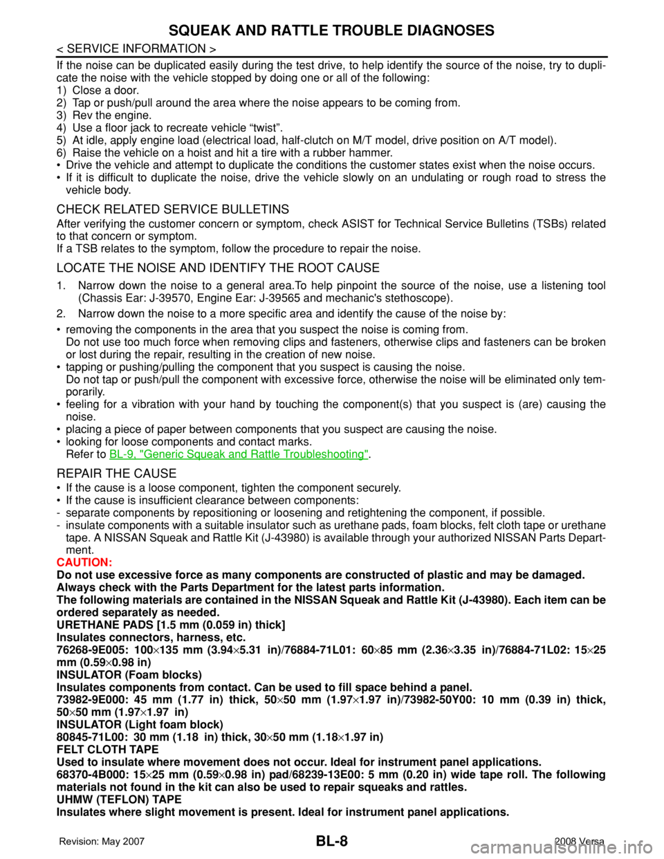
If the noise can be duplicated easily during the test drive, to help identify the source of the noise, try to dupli-
cate the noise with the vehicle stopped by doing one or all of the following:
1) Close a door.
2) Tap or push/pull around the area where the noise appears to be coming from.
3) Rev the engine.
4) Use a floor jack to recreate vehicle “twist”.
5) At idle, apply engine load (electrical load, half-clutch on M/T model, drive position on A/T model).
6) Raise the vehicle on a hoist and hit a tire with a rubber hammer.
• Drive the vehicle and attempt to duplicate the conditions the customer states exist when the noise occurs.
• If it is difficult to duplicate the noise, drive the vehicle slowly on an undulating or rough road to stress the
vehicle body.
CHECK RELATED SERVICE BULLETINS
After verifying the customer concern or symptom, check ASIST for Technical Service Bulletins (TSBs) related
to that concern or symptom.
If a TSB relates to the symptom, follow the procedure to repair the noise.
LOCATE THE NOISE AND IDENTIFY THE ROOT CAUSE
1. Narrow down the noise to a general area.To help pinpoint the source of the noise, use a listening tool
(Chassis Ear: J-39570, Engine Ear: J-39565 and mechanic's stethoscope).
2. Narrow down the noise to a more specific area and identify the cause of the noise by:
• removing the components in the area that you suspect the noise is coming from.
Do not use too much force when removing clips and fasteners, otherwise clips and fasteners can be broken
or lost during the repair, resulting in the creation of new noise.
• tapping or pushing/pulling the component that you suspect is causing the noise.
Do not tap or push/pull the component with excessive force, otherwise the noise will be eliminated only tem-
porarily.
• feeling for a vibration with your hand by touching the component(s) that you suspect is (are) causing the
noise.
• placing a piece of paper between components that you suspect are causing the noise.
• looking for loose components and contact marks.
Refer to BL-9, "
Generic Squeak and Rattle Troubleshooting".
REPAIR THE CAUSE
• If the cause is a loose component, tighten the component securely.
• If the cause is insufficient clearance between components:
- separate components by repositioning or loosening and retightening the component, if possible.
- insulate components with a suitable insulator such as urethane pads, foam blocks, felt cloth tape or urethane
tape. A NISSAN Squeak and Rattle Kit (J-43980) is available through your authorized NISSAN Parts Depart-
ment.
CAUTION:
Do not use excessive force as many components are constructed of plastic and may be damaged.
Always check with the Parts Department for the latest parts information.
The following materials are contained in the NISSAN Squeak and Rattle Kit (J-43980). Each item can be
ordered separately as needed.
URETHANE PADS [1.5 mm (0.059 in) thick]
Insulates connectors, harness, etc.
76268-9E005: 100×135 mm (3.94×5.31 in)/76884-71L01: 60×85 mm (2.36×3.35 in)/76884-71L02: 15×25
mm (0.59×0.98 in)
INSULATOR (Foam blocks)
Insulates components from contact. Can be used to fill space behind a panel.
73982-9E000: 45 mm (1.77 in) thick, 50×50 mm (1.97×1.97 in)/73982-50Y00: 10 mm (0.39 in) thick,
50×50 mm (1.97×1.97 in)
INSULATOR (Light foam block)
80845-71L00: 30 mm (1.18 in) thick, 30×50 mm (1.18×1.97 in)
FELT CLOTH TAPE
Used to insulate where movement does not occur. Ideal for instrument panel applications.
68370-4B000: 15×25 mm (0.59×0.98 in) pad/68239-13E00: 5 mm (0.20 in) wide tape roll. The following
materials not found in the kit can also be used to repair squeaks and rattles.
UHMW (TEFLON) TAPE
Insulates where slight movement is present. Ideal for instrument panel applications.