2008 NISSAN ROGUE Electrical steering
[x] Cancel search: Electrical steeringPage 60 of 309
Black plate (59,1)
Model "S35-D" EDITED: 2007/ 12/ 19
(indicating that the air bag is OFF) , it could be
that the person is a small adult, or is not sitting
on the seat properly.
If a child restraint must be used in the front seat,
the passenger air bag status light may or may
not be illuminated, depending on the size of the
child and the type of child restraint being used. If
the air bag status light is not illuminated
(indicating that the air bag might inflate in a
crash) , it could be that the child restraint or seat
belt is not being used properly. Make sure that
the child restraint is installed properly, the seat
belt is used properly and the occupant is
positioned properly. If the air bag status light is
not illuminated, reposition the occupant or child
restraint in a rear seat.
If the passenger air bag status light will not
illuminate even though you believe that the child
restraint, the seat belts and the occupant are
properly positioned, the system may be sensing
an unoccupied seat (in which case the air bag is
OFF) . Your NISSAN dealer can check that the
system is OFF by using a special tool. However,
until you have confirmed with your dealer that
your air bag is working properly, reposition the
occupant or child restraint in a rear seat.
The air bag system and passenger air bag status
light will take a few seconds to register a change
in the passenger seat status. However, if the
seat becomes unoccupied, the air bag status
light will remain off.If a malfunction occurs in the front passenger air
bag system, the supplemental air bag warning
light
, located in the meter and gauges area,
will blink. Have the system checked by a
NISSAN dealer.
Other supplemental front-impact air bag
precautions
WARNING
.Do not place any objects on the
steering wheel pad or on the instru-
ment panel. Also, do not place any
objects between any occupant and
the steering wheel or instrument
panel. Such objects may become
dangerous projectiles and cause
injury if the front air bag inflates.
.Do not place objects with sharp
edges on the seat. Also, do not
place heavy objects on the seat that
will leave permanent impressions in
the seat. Such objects can damage
the seat or occupant classification
sensor (pattern sensor) . This can
affect the operation of the air bag
system and result in serious perso-
nal injury.
.Do not use water or acidic cleaners(hot steam cleaners) on the seat.
This can damage the seat or occu-
pant classification sensor. This can
also affect the operation of the air
bag system and result in serious
personal injury.
.Immediately after inflation, several
front air bag system components
will be hot. Do not touch them; you
may severely burn yourself.
.No unauthorized changes should be
made to any components or wiring
of the supplemental air bag system.
This is to prevent accidental infla-
tion of the supplemental air bag or
damage to the supplemental air bag
system.
.Do not make unauthorized changes
to your vehicle’s electrical system,
suspension system or front end
structure. This could affect proper
operation of the front air bag sys-
tem.
.Tampering with the supplemental
air bag system may result in serious
personal injury. Tampering includes
changes to the steering wheel and
the instrument panel assembly by
Safety — Seats, seat belts and supplemental restraint system
1-47
Page 77 of 309
Black plate (77,1)
Model "S35-D" EDITED: 2007/ 12/ 19
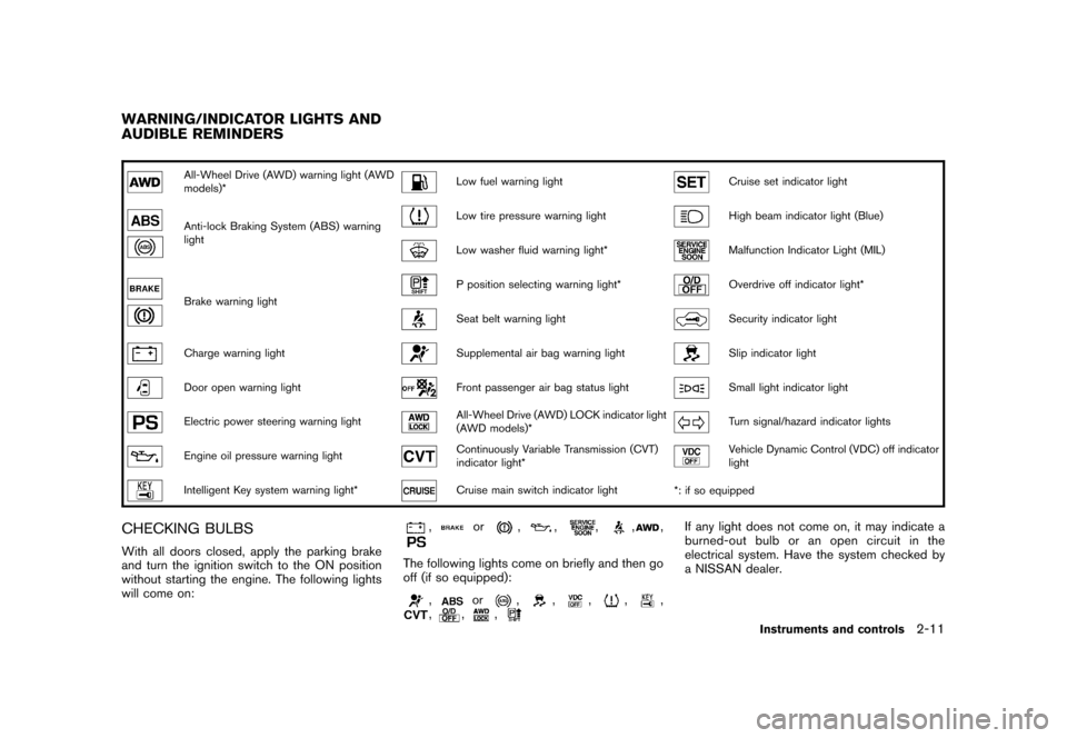
All-Wheel Drive (AWD) warning light (AWD
models)*
Low fuel warning light
Cruise set indicator light
Anti-lock Braking System (ABS) warning
light
Low tire pressure warning light
High beam indicator light (Blue)
Low washer fluid warning light*
Malfunction Indicator Light (MIL)
Brake warning light
P position selecting warning light*
Overdrive off indicator light*
Seat belt warning light
Security indicator light
Charge warning light
Supplemental air bag warning light
Slip indicator light
Door open warning light
Front passenger air bag status light
Small light indicator light
Electric power steering warning light
All-Wheel Drive (AWD) LOCK indicator light
(AWD models)*
Turn signal/hazard indicator lights
Engine oil pressure warning light
Continuously Variable Transmission (CVT)
indicator light*
Vehicle Dynamic Control (VDC) off indicator
light
Intelligent Key system warning light*
Cruise main switch indicator light
*: if so equipped
CHECKING BULBSWith all doors closed, apply the parking brake
and turn the ignition switch to the ON position
without starting the engine. The following lights
will come on:
,
or
,
,
,
,
,
The following lights come on briefly and then go
off (if so equipped):
,
or
,
,
,
,
,
,
,
,
If any light does not come on, it may indicate a
burned-out bulb or an open circuit in the
electrical system. Have the system checked by
a NISSAN dealer.
WARNING/INDICATOR LIGHTS AND
AUDIBLE REMINDERS
Instruments and controls
2-11
Page 190 of 309
Black plate (194,1)
Model "S35-D" EDITED: 2007/ 12/ 19
CONTINUOUSLY VARIABLE TRANS-
MISSION (CVT)The ignition lock is designed so that the ignition
switch cannot be turned to the LOCK position
until the selector lever is moved to the P (Park)
position.
.When turning the ignition switch to the
LOCK position, make sure that the selector
lever is in the P (Park) position.
.When removing the key from the ignition
switch (if it is inserted) , make sure that the
selector lever is in the P (Park) position.
When the ignition switch cannot be turned to
the LOCK position:
1. Move the selector lever to the P (Park)
position.
2. Turn the ignition switch slightly in the ON
direction.
3. TurntheignitionswitchtotheLOCK
position.
4. Remove the key, if it is inserted in the ignition
switch.
If the ignition switch is turned to the LOCK
position, the selector lever cannot be moved
from the P (Park) position. The selector lever can
be moved if the ignition switch is in the ON
position with the foot brake pedal depressed.The OFF position
*1
is between the LOCK and
ACC positions, although it is not marked on the
ignition switch.
STEERING LOCK
To lock steering wheel1. Turn the ignition switch to the LOCK
position.
2. Remove the key, if it is inserted in the ignition
switch.
3. Turn the steering wheel 1/6 of a turn
clockwise from the straight up position.To unlock steering wheel1. Insert the key into the ignition switch, if
necessary.
2. Gently turn the ignition switch while rotating
the steering wheel slightly right and left.KEY POSITIONS
LOCK (0)Except for the Intelligent Key equipped
model:
The key can only be removed from the ignition
switch at this position.
The steering lock can only be locked at this
position.For the Intelligent Key equipped model:
PUSH OFF -
The steering lock can only be locked at this
position.
PUSH ON -
The ignition switch will be unlocked while
carrying the Intelligent Key.
OFF (1)The engine is turned off with the steering wheel
unlocked.ACC (2)The electrical accessory power activates without
the engine turned on.ON (3)The ignition system and the electrical accessory
power activate without the engine turned on.START (4)The engine starter activates and the engine will
start. The ignition switch, when released, will
automatically turn to the ON position.
CAUTION
As soon as the engine has started,
release the ignition switch immediately.
5-10
Starting and driving
Page 196 of 309
Black plate (200,1)
Model "S35-D" EDITED: 2007/ 12/ 19
Accelerator downshift
— In D position —For passing or hill climbing, fully depress the
accelerator pedal to the floor. This shifts the
transmission down into a lower gear, depending
on the vehicle speed.High fluid temperature protection modeThis transmission has a high fluid temperature
protection mode. If the fluid temperature be-
comes too high (for example, when climbing
steep grades in high temperature with heavy
loads, such as when towing a trailer) , engine
power and, under some conditions, vehicle
speed will be decreased automatically to reduce
the chance of transmission damage. Vehicle
speed can be controlled with the accelerator
pedal, but the engine and vehicle speed may be
limited.Fail-safeIf the vehicle is driven under extreme
conditions, such as excessive wheel spin-
ning and subsequent hard braking, the
fail-safe system may be activated. The MIL
may illuminate to indicate the fail-safe
mode is activated. (See “Malfunction In-
dicator Light (MIL)” in the “2. Instruments
and controls” section.) This will occur even
if all electrical circuits are functioning
properly. In this case, turn the ignition
switch to the OFF position and wait for 10seconds. Then turn the switch back to the
ON position. The vehicle should return to
its normal operating condition. If it does
not return to its normal operating condi-
tion, have a NISSAN dealer check the
transmission and repair if necessary.
WARNING
When the high fluid temperature pro-
tection mode or fail-safe operation
occurs, vehicle speed may be gradually
reduced. The reduced speed may be
lower than other traffic, which could
increase the chance of a collision. Be
especially careful when driving. If ne-
cessary, pull to the side of the road at a
safe place and allow the transmission
to return to normal operation, or have it
repaired if necessary.
SSD0667
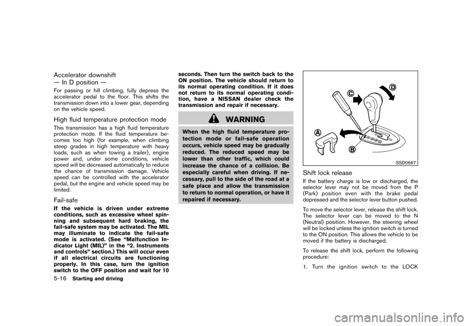
Shift lock releaseIf the battery charge is low or discharged, the
selector lever may not be moved from the P
(Park) position even with the brake pedal
depressed and the selector lever button pushed.
To move the selector lever, release the shift lock.
The selector lever can be moved to the N
(Neutral) position. However, the steering wheel
will be locked unless the ignition switch is turned
to the ON position. This allows the vehicle to be
moved if the battery is discharged.
To release the shift lock, perform the following
procedure:
1. Turn the ignition switch to the LOCK
5-16
Starting and driving
Page 210 of 309
Black plate (214,1)
Model "S35-D" EDITED: 2007/ 12/ 19
will lose even more traction.
.Allow more stopping distance under
these conditions. Braking should be
started sooner than on dry pave-
ment.
.Allow greater following distances
on slippery roads.
.Watch for slippery spots (glare ice) .
These may appear on an otherwise
clear road in shaded areas. If a
patch of ice is seen ahead, brake
before reaching it. Try not to brake
while on the ice, and avoid any
sudden steering maneuvers.
.Do not use cruise control on slip-
pery roads.
.Snow can trap dangerous exhaust
gases under your vehicle. Keep
snow clear of the exhaust pipe and
from around your vehicle.
ENGINE BLOCK HEATER (if so
equipped)Engine block heatersare available through
NISSAN dealers to assist in cold temperature
starting. The engine block heater should be
used when the outside temperature is 208F
(�78C) or lower.
To use the engine block heater1. Turn the engine off.
2. Open the hood and unwrap the engine
block heater cord.
3. Plug the engine block heater cord into a
grounded 3-wire, 3-pronged extension cord.
4. Plug the extension cord into a Ground Fault
Interrupt (GFI) protected, grounded 110-
volt AC (VAC) outlet.
5. The engine block heater must be plugged in
for at least 2 - 4 hours, depending on
outside temperatures, to properly warm the
engine coolant. Use an appropriate timer to
turn the engine block heater on.
6. Before starting the engine, unplug and
properly store the cord to keep it away from
moving parts.
WARNING
.Do not use your engine block heater
with an ungrounded electrical sys-
tem or a 2-pronged adapter. You can
be seriously injured by an electrical
shock if you use an ungrounded
connection.
.Disconnect and properly store the
engine block heater cord beforestarting the engine. Damage to the
cord could result in an electrical
shock and can cause serious injury.
.Use a heavy-duty 3-wire, 3-pronged
extension cord rated for at least
10A. Plug the extension cord into a
Ground Fault Interrupt (GFI) pro-
tected, grounded 110-VAC outlet.
Failure to use the proper extension
cord or a grounded outlet can result
in a fire or electrical shock and
cause serious personal injury.
5-30
Starting and driving
Page 220 of 309
Black plate (226,1)
Model "S35-D" EDITED: 2007/ 12/ 19
unnecessary electrical systems (lights, hea-
ter, air conditioner, etc.) .
3. Remove vent caps on the battery (if so
equipped) . Cover the battery with a firmly
wrung out moist cloth to reduce explosion
hazard.
4. Connect jumper cables in the sequence as
illustrated (
*1
?
*2
?
*3
?
*4).
For the vehicle equipped with Intelli-
gent Key system:
If the battery is discharged, the ignition
switch cannot be moved from the LOCK
position and, if the steering lock is
engaged, the steering wheel cannot be
moved. Connect the jumper cables to
the booster vehicle
*B
before turning
the ignition switch and disengaging the
steering lock.
CAUTION
.Always connect positive (+) to posi-
tive (+) and negative (�) to body
ground (for example, as illustrated) ,
not to the battery.
.Make sure the jumper cables do not
touch moving parts in the engine
compartment and that the cable
clamps do not contact any othermetal.
5. Start the engine of the booster vehicle
*B
and let it run for a few minutes.
6. Keep the engine speed of the booster
vehicle
*B
at about 2,000 rpm, and start
the engine of the vehicle
*A
being jump
started.
CAUTION
Do not keep the starter motor engaged
for more than 10 seconds. If the engine
does not start right away, turn the
ignition switch to the OFF position
and wait 10 seconds before trying
again.
7. After starting your engine, carefully discon-
nect the negative cable and then the positive
cable (
*4
?
*3
?
*2
?
*1).
8. Replace the vent caps (if so equipped) . Be
sure to dispose of the cloth used to cover
the vent holes as it may be contaminated
with corrosive acid.Do not attempt to start the engine by pushing.
CAUTION
Continuously Variable Transmission
(CVT) models cannot be push-started
or tow-started. Attempting to do so may
cause transmission damage.PUSH STARTING
6-10
In case of emergency