2008 NISSAN QASHQAI fuse
[x] Cancel search: fusePage 79 of 297
Downloaded from www.Manualslib.com manuals search engine WARNING
Take care as the power outlet and plug may be
hot during or immediately after use.
CAUTION
This power outlet is not designed for use with
a cigarette lighter unit.
Do not use with accessories that exceed a 12
volt, 120 W (10 A) power draw. Do not use
double adaptors or more than one electrical
accessory.
Use this power outlet with the engine running
(do not use for extended periods of time with
the engine stopped or idling).
Avoid using when the air conditioner, head-
lights or rear window defogger are on.
When not in use, be sure that the cap is
closed. Do not allow water to come into con-
tact with the outlet.
Before inserting or disconnecting a plug, be
sure to turn off the power switch of the elec-
trical accessory being used or the Acc power
of the vehicle.
Fully push the plug in sufficiently. If sufficient
contact is not made, the plug may overheat or
the internal temperature fuse may blow.
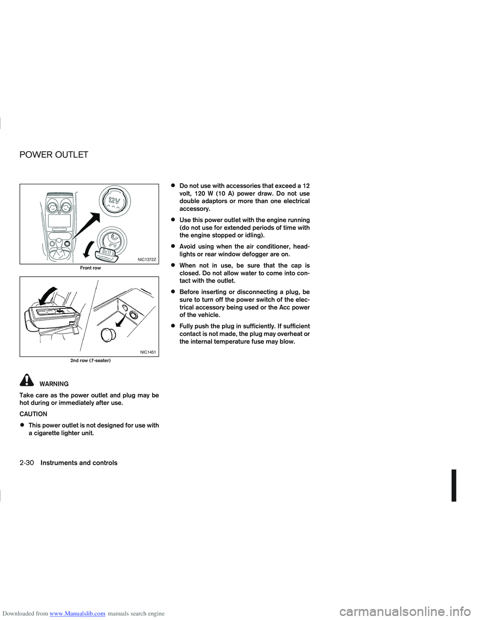
NIC1372Z
Front row
NIC1451
2nd row (7-seater)
POWER OUTLET
2-30Instruments and controls
Page 84 of 297
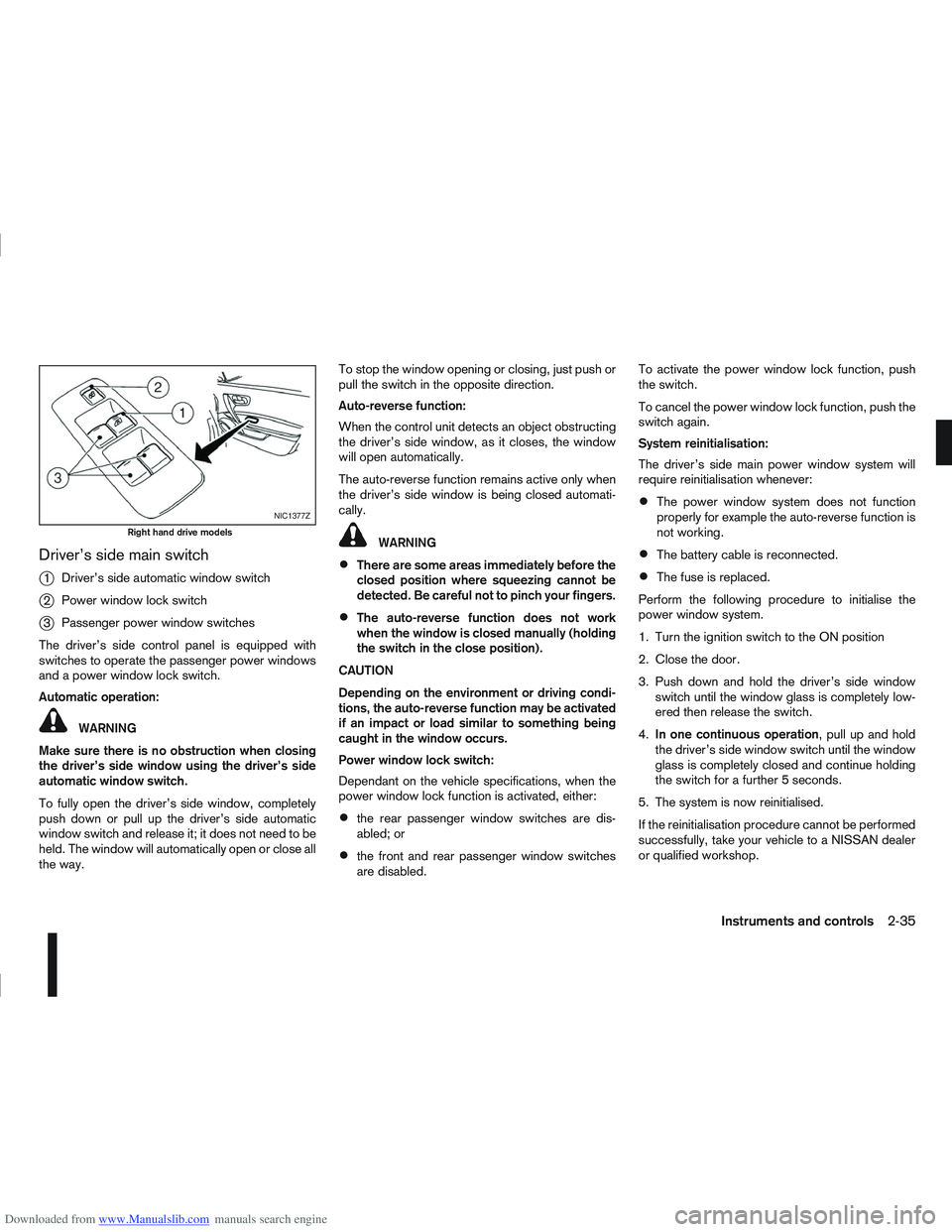
Downloaded from www.Manualslib.com manuals search engine Driver’s side main switch
j
1Driver’s side automatic window switch
j2Power window lock switch
j3Passenger power window switches
The driver’s side control panel is equipped with
switches to operate the passenger power windows
and a power window lock switch.
Automatic operation:
WARNING
Make sure there is no obstruction when closing
the driver’s side window using the driver’s side
automatic window switch.
To fully open the driver’s side window, completely
push down or pull up the driver’s side automatic
window switch and release it; it does not need to be
held. The window will automatically open or close all
the way. To stop the window opening or closing, just push or
pull the switch in the opposite direction.
Auto-reverse function:
When the control unit detects an object obstructing
the driver’s side window, as it closes, the window
will open automatically.
The auto-reverse function remains active only when
the driver’s side window is being closed automati-
cally.
WARNING
There are some areas immediately before the
closed position where squeezing cannot be
detected. Be careful not to pinch your fingers.
The auto-reverse function does not work
when the window is closed manually (holding
the switch in the close position).
CAUTION
Depending on the environment or driving condi-
tions, the auto-reverse function may be activated
if an impact or load similar to something being
caught in the window occurs.
Power window lock switch:
Dependant on the vehicle specifications, when the
power window lock function is activated, either:
the rear passenger window switches are dis-
abled; or
the front and rear passenger window switches
are disabled. To activate the power window lock function, push
the switch.
To cancel the power window lock function, push the
switch again.
System reinitialisation:
The driver’s side main power window system will
require reinitialisation whenever:
The power window system does not function
properly for example the auto-reverse function is
not working.
The battery cable is reconnected.
The fuse is replaced.
Perform the following procedure to initialise the
power window system.
1. Turn the ignition switch to the ON position
2. Close the door.
3. Push down and hold the driver’s side window switch until the window glass is completely low-
ered then release the switch.
4. In one continuous operation , pull up and hold
the driver’s side window switch until the window
glass is completely closed and continue holding
the switch for a further 5 seconds.
5. The system is now reinitialised.
If the reinitialisation procedure cannot be performed
successfully, take your vehicle to a NISSAN dealer
or qualified workshop.
NIC1377Z
Right hand drive models
Instruments and controls2-35
Page 86 of 297
Downloaded from www.Manualslib.com manuals search engine SYSTEM REINITIALISATION
The C-View® sunshade will require reinitialisation
whenever:
The sunshade system does not function prop-
erly.
The battery cable is reconnected.
The fuse is replaced.
Perform the following procedure to initialise the sun-
shade system.
1. Make sure the vehicle battery is connected.
2. Turn the ignition switch to the ON position.
3. Press and hold the “CLOSE” side of the switch. The system will now proceed as follows:
a. If open, the sunshade will start moving to the closed position.
b. After a few seconds, the system will fully open the sunshade.
c. From the fully open position, it returns to the closed position.
4. After reaching the closed position, release the sunshade switch.
5. The sunshade system is now reinitialised. NOTE
Do not disconnect the power for at least 2
seconds. If the reinitialisation procedure cannot be performed
successfully, take your vehicle to a NISSAN dealer
or qualified workshop.
CAUTION
Do not use for extended periods of time with the
engine stopped. This could discharge the bat-
tery.
NOTE
The interior lights will go off after approximately
15 minutes unless the ignition switch is in the
Acc or ON position.
FRONT ROOM LIGHT
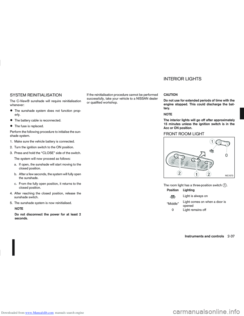
The room light has a three-position switchj1.
Position Lighting
mLightisalwayson
“Middle” Light comes on when a door is
opened
0 Light remains off
NIC1573
INTERIOR LIGHTS
Instruments and controls2-37
Page 132 of 297
Downloaded from www.Manualslib.com manuals search engine Band select button
Press the button to change the reception
wave band as follows:
FM1 →FM 2 →FM T →MW →LW →FM1
When button is pressed while the igni-
tion switch is in the Acc or ON position, the radio
will come on at the last received radio station. If the
CD is already playing, pressing the but-
ton will switch off the CD play mode and the last
received radio station will be selected.
FM Auto store
When the button is pressed for more
than 1.5 seconds and the six strongest stations are
stored in the preset (1 to 6) of the FM T band. Dur-
ing the search, a notification message [AU-
TOSTORE] appears in the display and the sound is
muted until the operation is complete. Once com-
pleted, the radio selects preset 1.
Manual tuning buttons
WARNING
The radio should not be tuned while driving in
order for full attention to be given to the driving
operation.
Press the
orbutton repeatedly to in-
crease or decrease the frequency. The frequency increases or decreases in steps of
100 kHz on the FM band, 9kHz on the MW band,
and 3 kHz on the LW band.
If the
orbutton is held down with a long
press, the frequency will continuously increase or
decrease until the button is released.
SEEK tuning buttons
Pressing briefly on theorbutton starts the
tuning mode. The radio tuner seeks from low to high
or high to low frequencies and stops at the next
broadcasting station. During seek mode, the audio
output is muted. If no broadcasting station can be
found within the complete band cycle, it will return
to the initial frequency.
If the
orbutton is held down with a long
press, the seek mode will continuously increase or
decrease until the button is released. When the but-
ton is released, the seek mode will seek the next
broadcasting station.
Preset station buttonsj1j2j3j4j5j6
Pressing a preset button for less than 2 seconds will
select the stored radio station.
Pressing a preset button for more than 2 seconds
will cause the station currently being received to be
stored against that preset button.
Eighteen stations can be stored in the FM band.
(Six each for FM1, FM2 and FMT)
Six stations can be set for both the MW and LW
bands. If the battery is disconnected, or if the fuse blows,
the radio memory will be erased. In that case, reset
the desired stations after battery connection or fuse
replacement.
Radio data system (RDS) operation
The RDS is a system through which encoded digital
information is transmitted by FM radio station in ad-
dition to the normal FM-radio broadcasting. The
RDS provides information services such as station
name, traffic information and news.
NOTE
In some countries or regions, some of these ser-
vices may not be available.
Alternative Frequency (AF) mode:
The AF mode operates in the FM (radio) mode.
The AF mode operates both in the FM (radio)
and CD mode (if FM was previously selected in
the radio mode).
When AF mode has been set to the “ON” posi-
tion in the user set up menu mode, the [AF] indi-
cator comes on. For activation or deactivation
details, see “MENU button” later in this section.
The AF function compares signal strengths and se-
lects the station with the optimum reception condi-
tions for the currently tuned-in station.
Display screen, heater and air conditioner, and audio system4-25
Page 140 of 297

Downloaded from www.Manualslib.com manuals search engine Eighteen stations can be stored in the FM band.
(Six each for FM1, FM2 and FMT)
Six stations can be set for the AM band.
If the battery is disconnected, or if the fuse blows,
the radio memory will be erased. In that case, reset
the desired stations after battery connection or fuse
replacement.
Radio data system (RDS) operation
The RDS is a system through which encoded digital
information is transmitted by FM radio stations in
addition to the normal FM radio broadcasting. The
RDS provides information services such as station
name, traffic information, or news.
NOTE
In some countries or regions, some of these ser-
vices may not be available.
Alternative Frequency (AF) mode:
The AF mode operates in the FM (radio) mode.
The AF mode operates in the FM (radio), AUX or
CD mode (if FM was previously selected in the
radio mode).
The AF function compares signal strengths and
selects the station with the optimum reception
conditions for the currently tuned-in station.
RDS functions
Programme Service (PS) function (station name
display function):
When an RDS station is tuned in with seek or manual
tuning, the RDS data is received and the PS name
is displayed.
TA Traffic announcement
This function operates in FM (Radio), CD or AUX
mode.
Pressing the
The TA indicator is displayed while TA mode is
on.
When
switched off and the TA indicator will disappear
from the display.
Traffic announcement interrupt function:
When a traffic announcement is received, the an-
nouncement is tuned in and the display shows a
notification message with the radio station name e.g.
[TA: Radio 1].
Once the traffic announcement has finished, the unit
returns to the source that was active before the traf-
fic announcement started.
If
the traffic announcement interrupt mode is can-
celled. The TA mode returns to the standby mode
and the audio unit returns to the previous source.
SETUP BUTTON
To configure Audio, Clock, Bluetooth, Language or
Scroll direction settings, perform the following pro-
cedure:
1. Press the
2. Turn the
clockwise, the display will appear in the following
order:
[Audio] ⇔[Clock] ⇔[Bluetooth] ⇔[Language]
⇔ [Scroll Direction]
After the desired levels have been set, press either
the
(Back) button repeatedly, the
button, or wait for 8 seconds without pressing any
buttons to exit the menu screen.
Display brightness (Day/Night mode)
Press the
switch the display brightness between the daytime
and nighttime mode.
Audio adjustments
Press the
screen then select [Audio].
Each time the
will change as follows:
[Bass] →[Treble] →[Balance] →[Fade] →[AUX
VOL] →[SPD VOL] →setup menu screen [Audio]
→ [Bass]
Display screen, heater and air conditioner, and audio system4-33
Page 231 of 297

Downloaded from www.Manualslib.com manuals search engine 8Maintenance and do-it-yourself
Maintenance and do-it-yourself
Maintenance requirements ....................................... 8-2
Scheduled maintenance...................................... 8-2
General maintenance .......................................... 8-2
Where to go for service ...................................... 8-2
General maintenance ............................................... 8-2 Explanation of general maintenance items ........... 8-2
Maintenance precautions ......................................... 8-4
Engine compartment ................................................ 8-5
Engine cooling system ............................................. 8-6 Checking engine coolant level............................. 8-6
Changing engine coolant .................................... 8-6
Engine oil................................................................. 8-8 Checking engine oil level .................................... 8-8
Changing engine oil ............................................ 8-9
Changing engine oil filter .................................... 8-11
Protect the environment ...................................... 8-13
Fuel filter (Diesel engine models) ............................. 8-13 Draining water .................................................... 8-13
Bleeding the fuel system ..................................... 8-14
Automatic transmission fluid (ATF) ........................... 8-14
Continuously variable transmission (CVT) fluid ......... 8-14
Brakes ..................................................................... 8-15 Checking brake pedal......................................... 8-15
Checking handbrake........................................... 8-15
Brake and clutch fluid .............................................. 8-15
Window washer fluid/headlight cleaner fluid
(where fitted) ........................................................... 8-16
Battery..................................................................... 8-17 Vehicle battery .................................................... 8-17
Jump-starting ...................................................... 8-19 Integrated keyfob/Intelligent Key battery
replacement........................................................ 8-19
Drive belts ............................................................... 8-21
Spark plugs (Petrol engine models).......................... 8-21
Air cleaner filter........................................................ 8-21 Viscous paper type ............................................. 8-22
Dry paper type (where fitted) .............................. 8-22
Wiper blades ........................................................... 8-22 Cleaning ............................................................. 8-22
Front window wiper replacement ........................ 8-22
Back door window wiper replacement ................ 8-23
Windscreen washer nozzle ................................. 8-23
Fuses ...................................................................... 8-23 Passenger compartment ..................................... 8-23
Engine compartment ........................................... 8-24
Lights ...................................................................... 8-25 Headlights .......................................................... 8-25
Exterior lights ...................................................... 8-27
Interior lights....................................................... 8-27
Light locations .................................................... 8-27
Wheels and tyres ..................................................... 8-31 Tyre inflation pressure......................................... 8-31
Types of tyres ..................................................... 8-31
Snow chains....................................................... 8-32
Tyre rotation ....................................................... 8-32
Tyre wear and damage ....................................... 8-33
Tyre age ............................................................. 8-33
Changing tyres and wheels ................................. 8-33
Four-wheel drive (4WD) models ......................... 8-33
Wheel balance.................................................... 8-33
Page 254 of 297
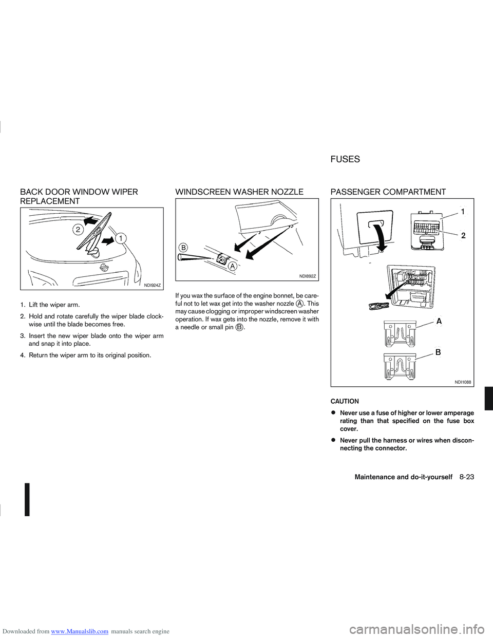
Downloaded from www.Manualslib.com manuals search engine BACK DOOR WINDOW WIPER
REPLACEMENT
1. Lift the wiper arm.
2. Hold and rotate carefully the wiper blade clock-wise until the blade becomes free.
3. Insert the new wiper blade onto the wiper arm and snap it into place.
4. Return the wiper arm to its original position.
WINDSCREEN WASHER NOZZLE
If you wax the surface of the engine bonnet, be care-
ful not to let wax get into the washer nozzlejA . This
may cause clogging or improper windscreen washer
operation. If wax gets into the nozzle, remove it with
aneedleorsmallpin
jB.
PASSENGER COMPARTMENT
CAUTION
Never use a fuse of higher or lower amperage
rating than that specified on the fuse box
cover.
Never pull the harness or wires when discon-
necting the connector.
NDI924Z
NDI892Z
NDI1088
FUSES
Maintenance and do-it-yourself8-23
Page 255 of 297
Downloaded from www.Manualslib.com manuals search engine Be careful not to damage the connector sup-
port bracket when disconnecting the connec-
tor.
If any electrical equipment does not operate, check
for an open fuse.
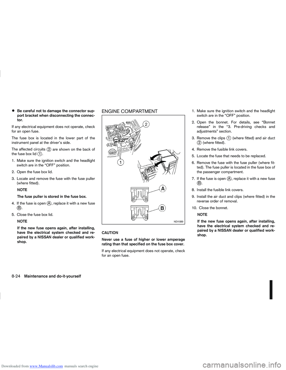
The fuse box is located in the lower part of the
instrument panel at the driver’s side.
The affected circuits
j2 are shown on the back of
the fuse box lidj1.
1. Make sure the ignition switch and the headlight switch are in the “OFF” position.
2. Open the fuse box lid.
3. Locate and remove the fuse with the fuse puller (where fitted).
NOTE
The fuse puller is stored in the fuse box.
4. If the fuse is open
jA , replace it with a new fusejB.
5. Close the fuse box lid. NOTE
If the new fuse opens again, after installing,
have the electrical system checked and re-
paired by a NISSAN dealer or qualified work-
shop.
ENGINE COMPARTMENT
CAUTION
Never use a fuse of higher or lower amperage
rating than that specified on the fuse box cover.
If any electrical equipment does not operate, check
for an open fuse. 1. Make sure the ignition switch and the headlight
switch are in the “OFF” position.
2. Open the bonnet. For details, see “Bonnet release” in the “3. Pre-driving checks and
adjustments” section.
3. Remove the clips
j1 (where fitted) and air ductj2 (where fitted).
4. Remove the fusible link covers.
5. Locate the fuse that needs to be replaced.
6. Remove the fuse with the fuse puller (where fit- ted). The fuse puller is located in the fuse box of
the passenger compartment.
7. If the fuse is open
jA , replace it with a new fusejB.
8. Install the fusible link covers.
9. Install the air duct and clips (where fitted) in the reverse order of removal.
10. Close the bonnet. NOTE
If the new fuse opens again, after installing,
have the electrical system checked and re-
paired by a NISSAN dealer or qualified work-
shop.
NDI1089
8-24Maintenance and do-it-yourself