2008 NISSAN PATHFINDER tire pressure
[x] Cancel search: tire pressurePage 392 of 448

Checking tire pressure
1. Remove the valve stem cap from the
tire.
2. Press the pressure gauge squarely
onto the valve stem. Do not press too
hard or force the valve stem side-
ways, or air will escape. If the hissing
sound of air escaping from the tire is
heard while checking the pressure,
reposition the gauge to eliminate this
leakage.
3. Remove the gauge.4. Read the tire pressure on the gauge
stem and compare to the specifica-
tion shown on the Tire Placard (if so
equipped) or the Tire and Loading
Information label (if so equipped) .
5. Add air to the tire as needed. If too
much air is added, press the core of
the valve stem briefly with the tip of
the gauge stem to release pressure.
Recheck the pressure and add or
release air as needed.
6. Install the valve stem cap.
7. Check the pressure of all other tires,
including the spare.
Size Cold Tire Infla-
tion Pressure
Front Original Tire:
P245/75R16
P265/65R17
P265/70R16
P265/75R16
P265/60R18240 kPa, 35 PSI
Rear Original Tire:
P245/75R16
P265/65R17
P265/70R16
P265/75R16
P265/60R18240 kPa, 35 PSI
Spare Tire:
P245/75R16
P265/65R17
P265/70R16
P265/75R16
P265/60R18240 kPa, 35 PSI
LDI0393
8-36Maintenance and do-it-yourself
ZREVIEW COPYÐ2008 Pathfinder(pat)
Owners ManualÐUSA_English(nna)
03/23/07Ðdebbie
X
Page 394 of 448

s2TIN (Tire Identification Number) for a
new tire (example: DOT XX XX XXX
XXXX)
1. DOT: Abbreviation for the9Depart-
ment Of Transportation.9The symbol
can be placed above, below or to the
left or right of Tire Identification Num-
ber.
2. Two-digit code: Manufacturer’s
identification mark
3. Two-digit code: Tire size4. Three-digit code: Tire type code
(Optional)
5. Three-digit code: Date of Manufac-
ture
6. Four numbers represent the week
and year the tire was built. For ex-
ample, the numbers 3103 means the
31st week of 2003. If these numbers
are missing, then look on the other
sidewall of the tire.
s3Tire ply composition and materialThe number of layers or plies of rubber-
coated fabric in the tire. Tire manufactur-
ers also must indicate the materials in the
tire, which include steel, nylon, polyester,
and others.
s4Maximum permissible inflation pres-
sure
This number is the greatest amount of air
pressure that should be put in the tire. Do
not exceed the maximum permissible in-
flation pressure.
s5Maximum load rating
This number indicates the maximum load
in kilograms and pounds that can be car-
ried by the tire. When replacing the tires
on the vehicle, always use a tire that has
the same load rating as the factory in-
stalled tire.
s6Term of “tubeless” or “tube type”
Indicates whether the tire requires an in-
ner tube (“tube type”) or not (“tubeless”) .
Example
WDI0396
8-38Maintenance and do-it-yourself
ZREVIEW COPYÐ2008 Pathfinder(pat)
Owners ManualÐUSA_English(nna)
03/23/07Ðdebbie
X
Page 397 of 448

Wheel nut tightening torque:
98 ft-lb (133 N·m)
The wheel nuts must be kept tight-
ened to specifications at all times. It
is recommended that wheel nuts be
tightened to specification at each
tire rotation interval.
WARNING
cAfter rotating the tires, check and
adjust the tire pressure.
cRetighten the wheel nuts when
the vehicle has been driven for
600 miles (1,000 km) (also in
cases of a flat tire, etc.) .
cDo not include the spare tire in
the tire rotation.
cFor additional information re-
garding tires, refer to “Important
Tire Safety Information” (US) or
“Tire Safety Information”
(Canada) in the Warranty Infor-
mation Booklet.
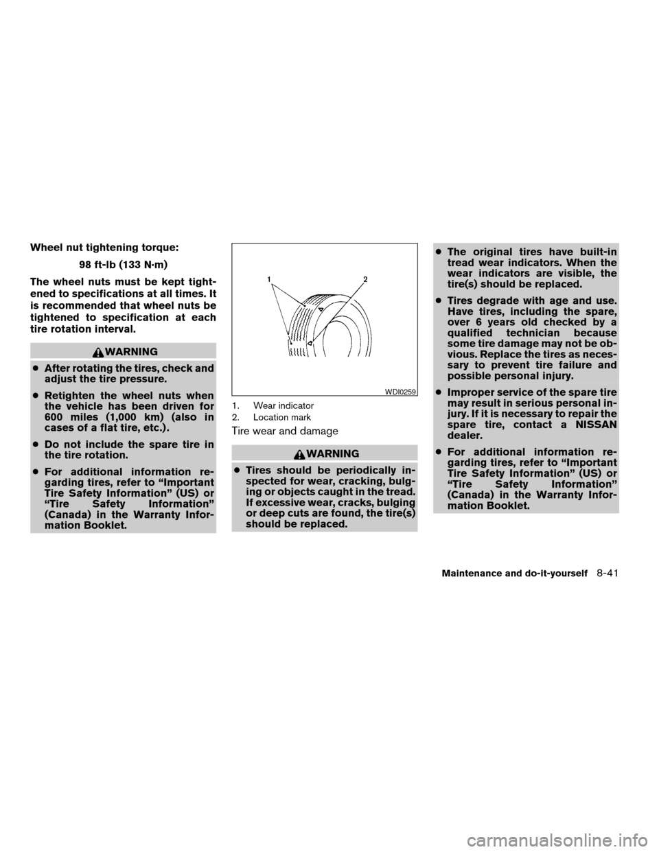
1. Wear indicator
2. Location mark
Tire wear and damage
WARNING
cTires should be periodically in-
spected for wear, cracking, bulg-
ing or objects caught in the tread.
If excessive wear, cracks, bulging
or deep cuts are found, the tire(s)
should be replaced.cThe original tires have built-in
tread wear indicators. When the
wear indicators are visible, the
tire(s) should be replaced.
cTires degrade with age and use.
Have tires, including the spare,
over 6 years old checked by a
qualified technician because
some tire damage may not be ob-
vious. Replace the tires as neces-
sary to prevent tire failure and
possible personal injury.
cImproper service of the spare tire
may result in serious personal in-
jury. If it is necessary to repair the
spare tire, contact a NISSAN
dealer.
cFor additional information re-
garding tires, refer to “Important
Tire Safety Information” (US) or
“Tire Safety Information”
(Canada) in the Warranty Infor-
mation Booklet.
WDI0259
Maintenance and do-it-yourself8-41
ZREVIEW COPYÐ2008 Pathfinder(pat)
Owners ManualÐUSA_English(nna)
03/23/07Ðdebbie
X
Page 398 of 448

Replacing wheels and tires
When replacing a tire, use the same size, tread
design, speed rating and load carrying capacity
as originally equipped. Recommended types and
sizes are shown in “Wheels and tires” in the
“Technical and consumer information” section of
this manual.
WARNING
cThe use of tires other than those recom-
mended or the mixed use of tires of
different brands, construction (bias,
bias-belted or radial) , or tread patterns
can adversely affect the ride, braking,
handling, ground clearance, body-to-
tire clearance, tire chain clearance,
speedometer calibration, headlight aim
and bumper height. Some of these ef-
fects may lead to accidents and could
result in serious personal injury.cIf the wheels are changed for any rea-
son, always replace with wheels which
have the same off-set dimension.
Wheels of a different off-set could
cause premature tire wear, degrade ve-
hicle handling characteristics and/or
interference with the brake
discs/drums. Such interference can
lead to decreased braking efficiency
and/or early brake pad/shoe wear. Re-
fer to “Wheels and tires” in the “Techni-
cal and consumer information” section
of this manual for wheel off-set
dimensions.
cWhen a spare tire is mounted or a wheel
is replaced, tire pressure will not be
indicated, the TPMS will not function
and the low tire pressure warning light
will flash for approximately 1 minute.
The light will remain on after 1 minute.
Contact your NISSAN dealer as soon as
possible for tire replacement and/or
system resetting.
cReplacing tires with those not originally
specified by NISSAN could affect the
proper operation of the TPMS.cDo not install a damaged or deformed
wheel or tire even if it has been re-
paired. Such wheels or tires could have
structural damage and could fail with-
out warning.
cThe use of retread tires is not
recommended.
cFor additional information regarding
tires, refer to “Important Tire Safety In-
formation” (US) or “Tire Safety Informa-
tion” (Canada) in the Warranty Informa-
tion Booklet.
Four-wheel drive models
CAUTION
Always use tires of the same type, size,
brand, construction (bias, bias-belted or
radial) , and tread pattern on all four
wheels. Failure to do so may result in a
circumference difference between tires
on the front and rear axles which will
cause excessive tire wear and may dam-
age the transmission, transfer case and
differential gears.
8-42Maintenance and do-it-yourself
ZREVIEW COPYÐ2008 Pathfinder(pat)
Owners ManualÐUSA_English(nna)
03/23/07Ðdebbie
X
Page 399 of 448

If excessive tire wear is found, it is recommended
that all four tires be replaced with tires of the
same size, brand, construction and tread pattern.
The tire pressure and wheel alignment should
also be checked and corrected as necessary.
Contact a NISSAN dealer.
Wheel balance
Unbalanced wheels may affect vehicle handling
and tire life. Even with regular use, wheels can get
out of balance. Therefore, they should be bal-
anced as required.
Wheel balance service should be per-
formed with the wheels off the vehicle.
Spin balancing the wheels on the vehicle
could lead to mechanical damage.
cFor additional information regarding
tires, refer to “Important Tire Safety
Information” (US) or “Tire Safety Infor-
mation” (Canada) in the Warranty In-
formation Booklet .
Care of wheels
cWash the wheels when washing the vehicle
to maintain their appearance.
cClean the inner side of the wheels when the
wheel is changed or the underside of the
vehicle is washed.cDo not use abrasive cleaners when washing
the wheels.
cInspect wheel rims regularly for dents or
corrosion. Such damage may cause loss of
pressure or poor seal at the tire bead.
cNISSAN recommends waxing the road
wheels to protect against road salt in areas
where it is used during winter.
Maintenance and do-it-yourself8-43
ZREVIEW COPYÐ2008 Pathfinder(pat)
Owners ManualÐUSA_English(nna)
03/23/07Ðdebbie
X
Page 411 of 448

EMISSION CONTROL
INFORMATION LABEL
The emission control information label is at-
tached to the underside of the hood as shown.
TIRE AND LOADING INFORMATION
LABEL
The cold tire pressure is shown on the Tire and
Loading Information label. The label is located as
shown.
AIR CONDITIONER SPECIFICATION
LABEL
The air conditioner specification label is affixed to
the underside of the hood as shown.
WTI0173WTI0100WTI0167
Technical and consumer information9-11
ZREVIEW COPYÐ2008 Pathfinder(pat)
Owners ManualÐUSA_English(nna)
03/23/07Ðdebbie
X
Page 412 of 448

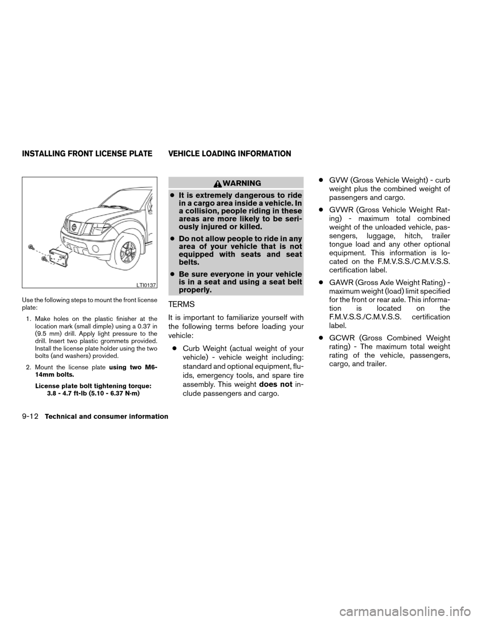
Use the following steps to mount the front license
plate:
1. Make holes on the plastic finisher at the
location mark (small dimple) using a 0.37 in
(9.5 mm) drill. Apply light pressure to the
drill. Insert two plastic grommets provided.
Install the license plate holder using the two
bolts (and washers) provided.
2. Mount the license plateusing two M6-
14mm bolts.
License plate bolt tightening torque:
3.8 - 4.7 ft-lb (5.10 - 6.37 N·m)
WARNING
cIt is extremely dangerous to ride
in a cargo area inside a vehicle. In
a collision, people riding in these
areas are more likely to be seri-
ously injured or killed.
cDo not allow people to ride in any
area of your vehicle that is not
equipped with seats and seat
belts.
cBe sure everyone in your vehicle
is in a seat and using a seat belt
properly.
TERMS
It is important to familiarize yourself with
the following terms before loading your
vehicle:
cCurb Weight (actual weight of your
vehicle) - vehicle weight including:
standard and optional equipment, flu-
ids, emergency tools, and spare tire
assembly. This weightdoes notin-
clude passengers and cargo.cGVW (Gross Vehicle Weight) - curb
weight plus the combined weight of
passengers and cargo.
cGVWR (Gross Vehicle Weight Rat-
ing) - maximum total combined
weight of the unloaded vehicle, pas-
sengers, luggage, hitch, trailer
tongue load and any other optional
equipment. This information is lo-
cated on the F.M.V.S.S./C.M.V.S.S.
certification label.
cGAWR (Gross Axle Weight Rating) -
maximum weight (load) limit specified
for the front or rear axle. This informa-
tion is located on the
F.M.V.S.S./C.M.V.S.S. certification
label.
cGCWR (Gross Combined Weight
rating) - The maximum total weight
rating of the vehicle, passengers,
cargo, and trailer.
LTI0137
INSTALLING FRONT LICENSE PLATE VEHICLE LOADING INFORMATION
9-12Technical and consumer information
ZREVIEW COPYÐ2008 Pathfinder(pat)
Owners ManualÐUSA_English(nna)
03/23/07Ðdebbie
X
Page 423 of 448

Tire pressures
cWhen towing a trailer, inflate the ve-
hicle tires to the recommended cold
tire pressure indicated on the Tire
and Loading Information label.
cTrailer tire condition, size, load rating
and proper inflation pressure should
be in accordance with the trailer and
tire manufacturer’s specifications.
Safety chains
Always use suitable safety chains between your
vehicle and the trailer. The safety chains should
be crossed and should be attached to the hitch,
not to the vehicle bumper or axle. The safety
chains can be attached to the bumper if the hitch
ball is mounted to the bumper. Be sure to leave
enough slack in the chains to permit turning
corners.
Trailer lights
CAUTION
When splicing into the vehicle electrical
system, a commercially available power-
type module/converter must be used to
provide power for all trailer lighting. This
unit uses the vehicle battery as a direct
power source for all trailer lights while
using the vehicle tail light, stoplight and
turn signal circuits as a signal source. The
module/converter must draw no more
that 15 milliamps from the stop and tail
lamp circuits. Using a module/converter
that exceeds these power requirements
may damage the vehicle’s electrical sys-
tem. See a reputable trailer dealer to ob-
tain the proper equipment and to have it
installed.
Trailer lights should comply with federal and/or
local regulations. For assistance in hooking up
trailer lights, contact a NISSAN dealer or repu-
table trailer dealer. Vehicles equipped with the
trailer tow package are equipped with a 4-pin
trailer harness connector. If your trailer is
equipped with a 7-pin connector, an adapter will
be needed to connect the trailer lights to the
vehicle. Adapters are available at NISSAN deal-
ers as well as auto parts stores and hitch retail-
ers.
Trailer brakes
If your trailer is equipped with a braking system,
make sure it conforms to federal and/or local
regulations and that it is properly installed.
WARNING
Never connect a trailer brake system di-
rectly to the vehicle brake system.
Pre-towing tips
cBe certain your vehicle maintains a level
position when a loaded and/or unloaded
trailer is hitched. Do not drive the vehicle if it
has an abnormal nose-up or nose-down
condition; check for improper tongue load,
overload, worn suspension or other possible
causes of either condition.
cAlways secure items in the trailer to prevent
load shift while driving.
cKeep the cargo load as low as possible in
the trailer to keep the trailer center of gravity
low.
cLoad the trailer so approximately 60% of the
trailer load is in the front half and 40% is in
the back half. Also make sure the load is
balanced side to side.
Technical and consumer information9-23
ZREVIEW COPYÐ2008 Pathfinder(pat)
Owners ManualÐUSA_English(nna)
03/23/07Ðarosenma
X