2008 NISSAN PATHFINDER steering
[x] Cancel search: steeringPage 76 of 448

2 Instruments and controls
Instrument panel...................................2-2
Meters and gauges................................2-3
Speedometer and odometer.....................2-4
Trip computer (if so equipped)...................2-5
Tachometer....................................2-6
Engine coolant temperature gauge...............2-6
Fuel gauge....................................2-7
Engine oil pressure gauge.......................2-8
Voltmeter......................................2-8
Compass display (if so equipped)...................2-9
Compass display...............................2-9
Warning/indicator lights and audible reminders......2-12
Checking bulbs...............................2-13
Warning lights................................2-13
Indicator lights................................2-18
Audible reminders.............................2-21
Security systems.................................2-22
Vehicle security system.........................2-22
NISSAN vehicle immobilizer system.............2-23
Windshield wiper and washer switch...............2-24
Switch operation..............................2-24
Rear window wiper and washer switch..............2-25Rear window and outside mirror (if so equipped)
defroster switch..................................2-26
Headlight and turn signal switch....................2-27
Headlight control switch........................2-27
Daytime running light system (Canada only)......2-29
Instrument brightness control...................2-30
Turn signal switch.............................2-30
Fog light switch (if so equipped)................2-30
Hazard warning flasher switch.....................2-31
Horn............................................2-31
Heated steering wheel (if so equipped).............2-32
Heated seat (if so equipped).......................2-32
Vehicle dynamic control (VDC) off switch............2-33
Hill descent control switch (if so equipped)..........2-33
Power outlet.....................................2-34
Storage.........................................2-36
Storage trays.................................2-36
Storage bins..................................2-37
2nd row under-seat storage bin.................2-38
Console box..................................2-38
Glove box....................................2-39
Sunglasses holder.............................2-39
ZREVIEW COPYÐ2008 Pathfinder(pat)
Owners ManualÐUSA_English(nna)
03/23/07Ðdebbie
X
Page 78 of 448

1. Ventilators (P. 4-35)
2. Headlight/fog light (if so equipped)/turn
signal switch (P. 2-27)
3. Steering wheel switch for audio control
(if so equipped) (P. 4-85)
4. Driver supplemental air bag/horn
(P. 1-40, P. 2-31)
5. Meters, gauges and warning/indicator
lights (P. 2-3, 2-12)
6. Cruise control main/set switches
(P. 5-18)
7. Windshield wiper/washer switch and
rear window wiper/washer switch
(P. 2-24, P. 2-25)
8. Navigation system* (if so equipped)
9. Navigation system* controls
(if so equipped)
10. Front passenger supplemental air bag
(P. 1-40)
11. Upper and lower glove box (P. 2-39)
12. Power outlet (P. 2-34)
13. Heated seat switch (if so equipped)
(P. 2-32)
14. Hill descent control switch
(if so equipped) (P. 2-33)
15. Shift selector lever (P. 5-12)
LIC1223
INSTRUMENT PANEL
2-2Instruments and controls
ZREVIEW COPYÐ2008 Pathfinder(pat)
Owners ManualÐUSA_English(nna)
03/23/07Ðdebbie
X
Page 79 of 448

16. Vehicle dynamic control (VDC) OFF
switch (P. 2-33)
17. 4WD shift switch (if so equipped)
(P. 5-21)
18. Storage
19. Passenger air bag status light (P. 1-49)
20. Climate controls (P. 4-36, 4-44)
21. Hazard warning flasher switch (P. 2-31)
22. Ignition switch (P. 5-8)
23. Tilt steering wheel control (P. 3-24)
24. Heated steering wheel switch
(if so equipped)
25. Pedal position adjustment switch
(if so equipped) (P. 3-24)
26. Outside mirror controls (P. 3-28)
*: Refer to the separate Navigation System Own-
er’s Manual (if so equipped) .
See the page number indicated in paren-
theses for operating details.
1. Warning/indicator lights
2. Tachometer
3. Speedometer
4. Fuel gauge
5. Voltmeter6. Odometer/Twin trip odometer/Trip com-
puter (if so equipped)
7. Engine oil pressure gauge
8. Engine coolant temperature gauge
WIC1040
METERS AND GAUGES
Instruments and controls2-3
ZREVIEW COPYÐ2008 Pathfinder(pat)
Owners ManualÐUSA_English(nna)
03/23/07Ðdebbie
X
Page 93 of 448

cIf the light illuminates while driving,
avoid sudden steering maneuvers or
abrupt braking, reduce vehicle speed,
pull off the road to a safe location and
stop the vehicle as soon as possible.
Driving with under-inflated tires may
permanently damage the tires and in-
crease the likelihood of tire failure. Se-
rious vehicle damage could occur and
may lead to an accident and could re-
sult in serious personal injury. Check
the tire pressure for all four tires. Adjust
the tire pressure to the recommended
COLD tire pressure shown on the Tire
and Loading Information label to turn
the low tire pressure warning light OFF.
If the light still comes on while driving
after adjusting the tire pressure, a tire
may be flat. If you have a flat tire, re-
place it with a spare tire as soon as
possible.
cWhen a spare tire is mounted or a wheel
is replaced, tire pressure will not be
indicated, the TPMS will not function
and the low tire pressure warning light
will flash for approximately 1 minute.
The light will remain on after 1 minute.
Contact your NISSAN dealer as soon as
possible for tire replacement and/or
system resetting.cReplacing tires with those not originally
specified by NISSAN could affect the
proper operation of the TPMS.
CAUTION
cThe TPMS is not a substitute for the
regular tire pressure check. Be sure to
check the tire pressure regularly.
cIf the vehicle is being driven at speeds
of less than 16 MPH (25 km/h) , the
TPMS may not operate correctly.
cBe sure to install the specified size of
tires to the 4 wheels correctly.
Low windshield washer fluid
warning light
This light comes on when the windshield washer
fluid is at a low level. Add windshield washer fluid
as necessary. See “Window washer fluid” in the
“Maintenance and do-it-yourself” section of this
manual.
Seat belt warning light and
chime
The light and chime remind you to fasten your
seat belts. The light illuminates whenever the
ignition key is turned to the ON or START position
and remains illuminated until the driver’s seat beltis fastened. At the same time, the chime sounds
for about 6 seconds unless the driver’s seat belt
is securely fastened.
The seat belt warning light may also illuminate if
the front passenger’s seat belt is not fastened
when the front passenger’s seat is occupied . For
7 seconds after the ignition switch is in the ON
position, the system does not activate the warn-
ing light for the front passenger.
Refer to “Seat belts” in the “Safety—Seats, seat
belts and supplemental restraint system” section
for precautions on seat belt usage.
Shift P warning light (if so
equipped)
This light blinks red and the key reminder chime
sounds if the shift selector lever is in any position
other than P (Park) and the ignition switch is in
the OFF position. Return the shift selector lever
to P (Park) with the ignition switch in the OFF
position and the light will turn off. Place the
ignition switch in the LOCK position and the
chime will turn off.
Supplemental air bag warning
light
When the ignition key is in the ON or START
position, the supplemental air bag warning light
Instruments and controls2-17
ZREVIEW COPYÐ2008 Pathfinder(pat)
Owners ManualÐUSA_English(nna)
03/23/07Ðdebbie
X
Page 107 of 448

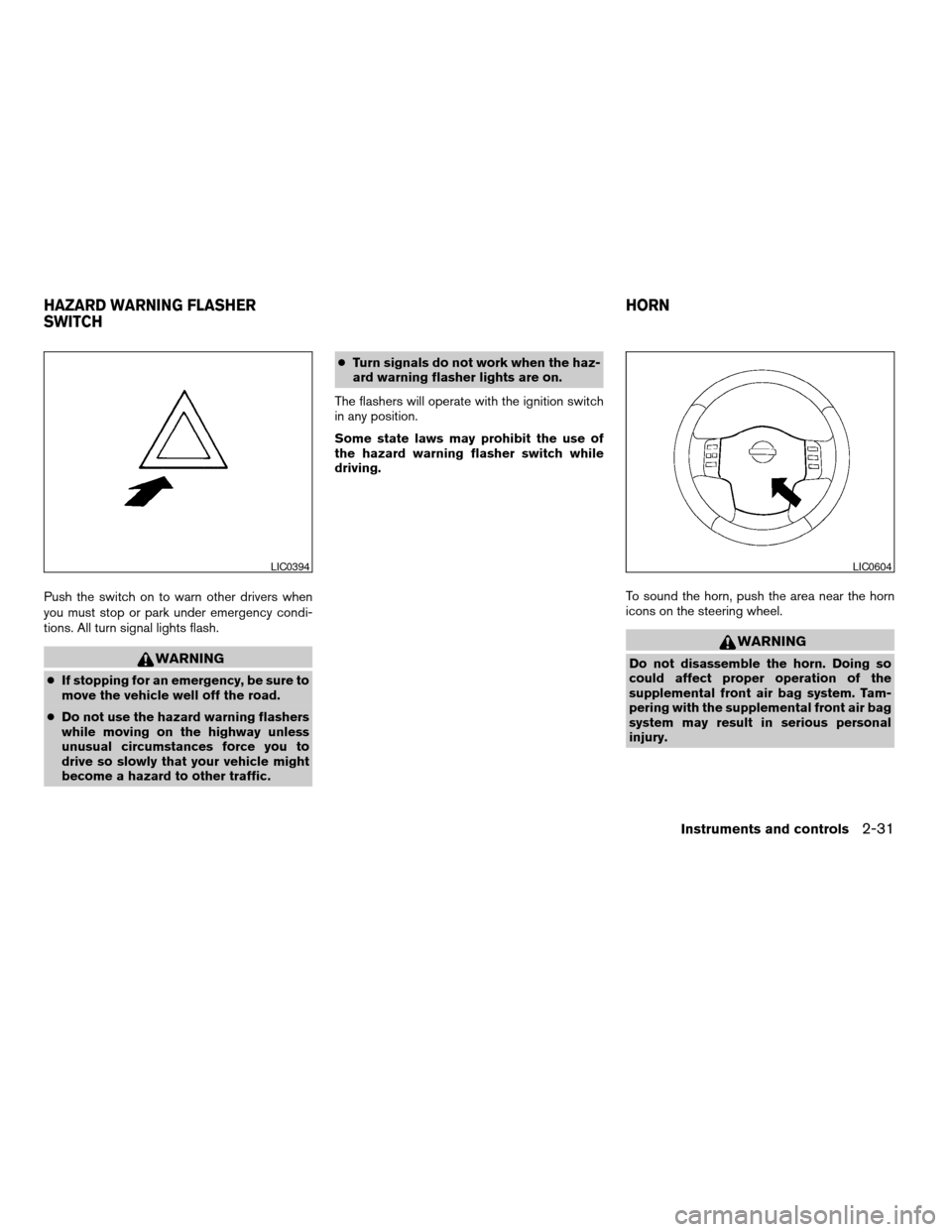
Push the switch on to warn other drivers when
you must stop or park under emergency condi-
tions. All turn signal lights flash.
WARNING
cIf stopping for an emergency, be sure to
move the vehicle well off the road.
cDo not use the hazard warning flashers
while moving on the highway unless
unusual circumstances force you to
drive so slowly that your vehicle might
become a hazard to other traffic.cTurn signals do not work when the haz-
ard warning flasher lights are on.
The flashers will operate with the ignition switch
in any position.
Some state laws may prohibit the use of
the hazard warning flasher switch while
driving.
To sound the horn, push the area near the horn
icons on the steering wheel.
WARNING
Do not disassemble the horn. Doing so
could affect proper operation of the
supplemental front air bag system. Tam-
pering with the supplemental front air bag
system may result in serious personal
injury.
LIC0394LIC0604
HAZARD WARNING FLASHER
SWITCHHORN
Instruments and controls2-31
ZREVIEW COPYÐ2008 Pathfinder(pat)
Owners ManualÐUSA_English(nna)
03/23/07Ðdebbie
X
Page 108 of 448

The heated steering wheel system is designed to
operate only when the surface temperature of the
steering wheel is below approximately 68°F
(20°C) .
Push the heated steering wheel switch to warm
the steering wheel after the engine starts. The
indicator light will come on.
If the surface temperature of the steering wheel is
below 68°F (20°C) , the system will heat the
steering wheel to approximately 86°F (30°C) .
The heater is controlled by a thermostat, auto-
matically turning the heater on and off. The indi-
cator light will remain on as long as the switch is
on.Push the switch again to turn the heated steering
wheel off manually. The indicator light will go off.
NOTE:
The heated steering wheel switch is
equipped with a 30 minute timer. After the
switch has been activated for 30 minutes,
the system will automatically turn off. If the
surface temperature of the steering wheel
is above 68°F (20°C) when the switch is
turned on, the system will not heat the
steering wheel. This is not a malfunction.
The front seats are warmed by built-in heaters (if
so equipped) .
1. Start the engine.
2. Push the LO or HI position of the switch, as
desired, depending on the temperature. The
indicator light in the switch will illuminate.
The heater is controlled by a thermostat,
automatically turning the heater on and off.
The indicator light will remain on as long as
the switch is on.
3. When the seat is warmed or before you
leave the vehicle, be sure to turn the switch
off.
LIC0421LIC1041
HEATED STEERING WHEEL (if so
equipped)HEATED SEAT (if so equipped)
2-32Instruments and controls
ZREVIEW COPYÐ2008 Pathfinder(pat)
Owners ManualÐUSA_English(nna)
03/23/07Ðdebbie
X
Page 110 of 448

cThe hill descent control may not control
the vehicle speed on a hill under all load
or road conditions. Always be prepared
to depress the brake pedal to control
vehicle speed. Failure to do so may re-
sult in a collision or serious personal
injury.
CAUTION
When the hill descent control system op-
erates continuously for a long time, the
temperature of the brake pads may in-
crease and the hill descent control system
may be temporarily disabled (the indicator
light will blink) . If the indicator light does
not come on continuously after blinking,
stop using the system.
The hill descent control system is designed to
reduce driver workload when going down steep
hills. The hill descent control system helps to
control vehicle speed so the driver can concen-
trate on steering the vehicle.
To activate the hill descent control system:
cthe automatic transmission selector lever
must be in forward or reverse gear,
cthe 4WD switch must be in the 4L position
and the vehicle speed must be under 15
mph (25 km/h) orcthe 4WD switch must be in the 4H position
and the vehicle speed must be under 21
mph (35 km/h) , and
cthe hill descent control system switch must
be ON.
The hill descent control indicator light will come
on when the system is activated. Also, the
stop/tail lights illuminate while the hill descent
control system applies the brakes to control ve-
hicle speed.
If the accelerator or brake pedal is depressed
while the hill descent control system is on, the
system will stop operating temporarily. As soon
as the accelerator or brake pedal is released, the
hill descent control system begins to function
again if the hill descent control operating condi-
tions are fulfilled.
The hill descent control indicator light blinks if the
switch is on and all conditions for system activa-
tion are not met or if the system becomes disen-
gaged for any reason.
To turn off the hill descent control system, push
the switch to the OFF position.
For additional information, see “Hill descent con-
trol system on indicator light” earlier in this sec-
tion and “Hill descent control system” in the
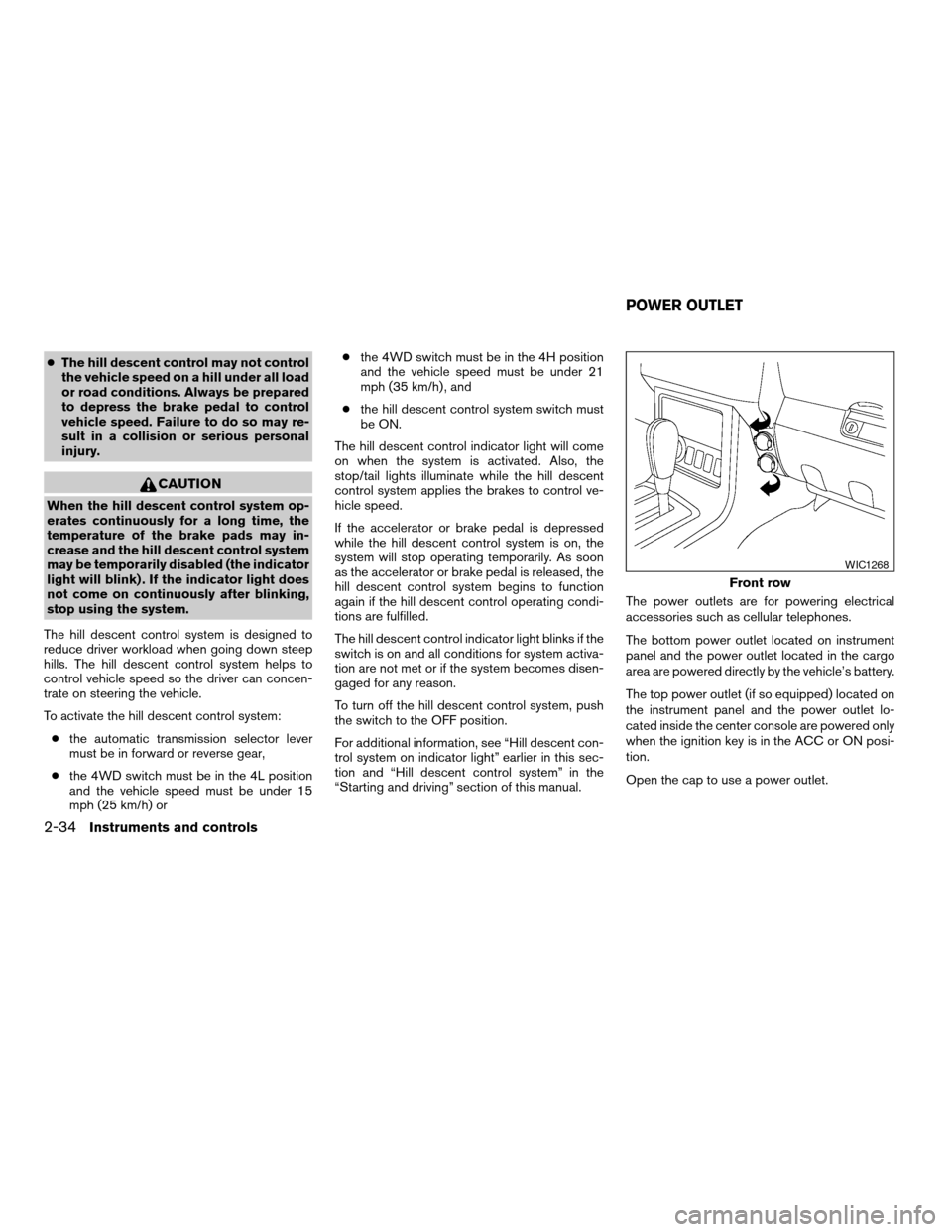
“Starting and driving” section of this manual.The power outlets are for powering electrical
accessories such as cellular telephones.
The bottom power outlet located on instrument
panel and the power outlet located in the cargo
area are powered directly by the vehicle’s battery.
The top power outlet (if so equipped) located on
the instrument panel and the power outlet lo-
cated inside the center console are powered only
when the ignition key is in the ACC or ON posi-
tion.
Open the cap to use a power outlet.
Front row
WIC1268
POWER OUTLET
2-34Instruments and controls
ZREVIEW COPYÐ2008 Pathfinder(pat)
Owners ManualÐUSA_English(nna)
03/23/07Ðdebbie
X
Page 135 of 448

3 Pre-driving checks and adjustments
Keys .............................................3-2
Intelligent keys (if so equipped)..................3-2
NISSAN vehicle immobilizer system keys..........3-3
Doors............................................3-4
Locking with key................................3-4
Locking with inside lock knob....................3-5
Locking with power door lock switch.............3-5
Child safety rear door lock.......................3-6
Intelligent Key system (if so equipped)...............3-6
Operating range................................3-8
Door locks/unlocks precaution...................3-8
Intelligent Key operation.........................3-9
How to use the remote keyless entry
function......................................3-12
Warning signals...............................3-14
Troubleshooting guide.........................3-14
Remote keyless entry system......................3-16
How to use remote keyless entry system.........3-16
Hood...........................................3-20
Lift gate.........................................3-20Lift gate release...............................3-21
Glass hatch......................................3-21
Fuel-filler door...................................3-22
Opening the fuel-filler lid.......................3-22
Fuel-filler cap.................................3-22
Steering wheel...................................3-24
Tilt operation..................................3-24
Pedal position adjustment (if so equipped)..........3-24
Sun visors.......................................3-25
Vanity mirrors.................................3-25
Mirrors..........................................3-26
Rearview mirror (if so equipped).................3-26
Automatic anti-glare rearview mirror
(if so equipped)...............................3-26
Outside mirrors...............................3-28
Automatic drive positioner (if so equipped)..........3-29
Memory storage function.......................3-29
Entry/exit function.............................3-31
System operation..............................3-31
ZREVIEW COPYÐ2008 Pathfinder(pat)
Owners ManualÐUSA_English(nna)
03/23/07Ðdebbie
X