2008 NISSAN LATIO height
[x] Cancel search: heightPage 1363 of 2771
DTC P0300 - P0304 MULTIPLE CYLINDER MISFIRE, NO. 1 - 4 CYLINDER MIS-
FIRE
EC-289
< SERVICE INFORMATION >
C
D
E
F
G
H
I
J
K
L
MA
EC
N
P O
6. Also check harness for short to power.
OK or NG
OK >> GO TO 14.
NG >> Repair open circuit or short to ground or short to power in harness or connectors.
14.CHECK AIR FUEL RATIO (A/F) SENSOR 1 HEATER
Refer to EC-154, "
Component Inspection".
OK or NG
OK >> GO TO 16.
NG >> GO TO 15.
15.REPLACE AIR FUEL RATIO (A/F) SENSOR 1
Replace air fuel ratio (A/F) sensor 1.
CAUTION:
• Discard any A/F sensor which has been dropped from a height of more than 0.5 m (19.7 in) onto a
hard surface such as a concrete floor; use a new one.
• Before installing new A/F sensor, clean exhaust system threads using Oxygen Sensor Thread
Cleaner tool J-43897-18 or J-43897-12 and approved anti-seize lubricant.
>>INSPECTION END
16.CHECK MASS AIR FLOW SENSOR
With CONSULT-II
1. Start engine and warm it up to normal operating temperature.
2. Check mass air flow sensor signal in “DATA MONITOR” mode with CONSULT-II.
With GST
1. Start engine and warm it up to normal operating temperature.
2. Check mass air flow sensor signal in Service $01 with GST.
OK or NG
OK >> GO TO 17.
NG >> Check connectors for rusted terminals or loose connections in the mass air flow sensor circuit or
ground. Refer to EC-167
.
17.CHECK SYMPTOM MATRIX CHART
Check items on the rough idle symptom in EC-88, "
Symptom Matrix Chart".
OK or NG
OK >> GO TO 18.
NG >> Repair or replace.
18.ERASE THE 1ST TRIP DTC
Some tests may cause a 1st trip DTC to be set.
Erase the 1st trip DTC from the ECM memory after performing the tests. Refer to EC-47, "
Emission-related
Diagnostic Information".
>> GO TO 19.
19.CHECK INTERMITTENT INCIDENT
Refer to EC-136
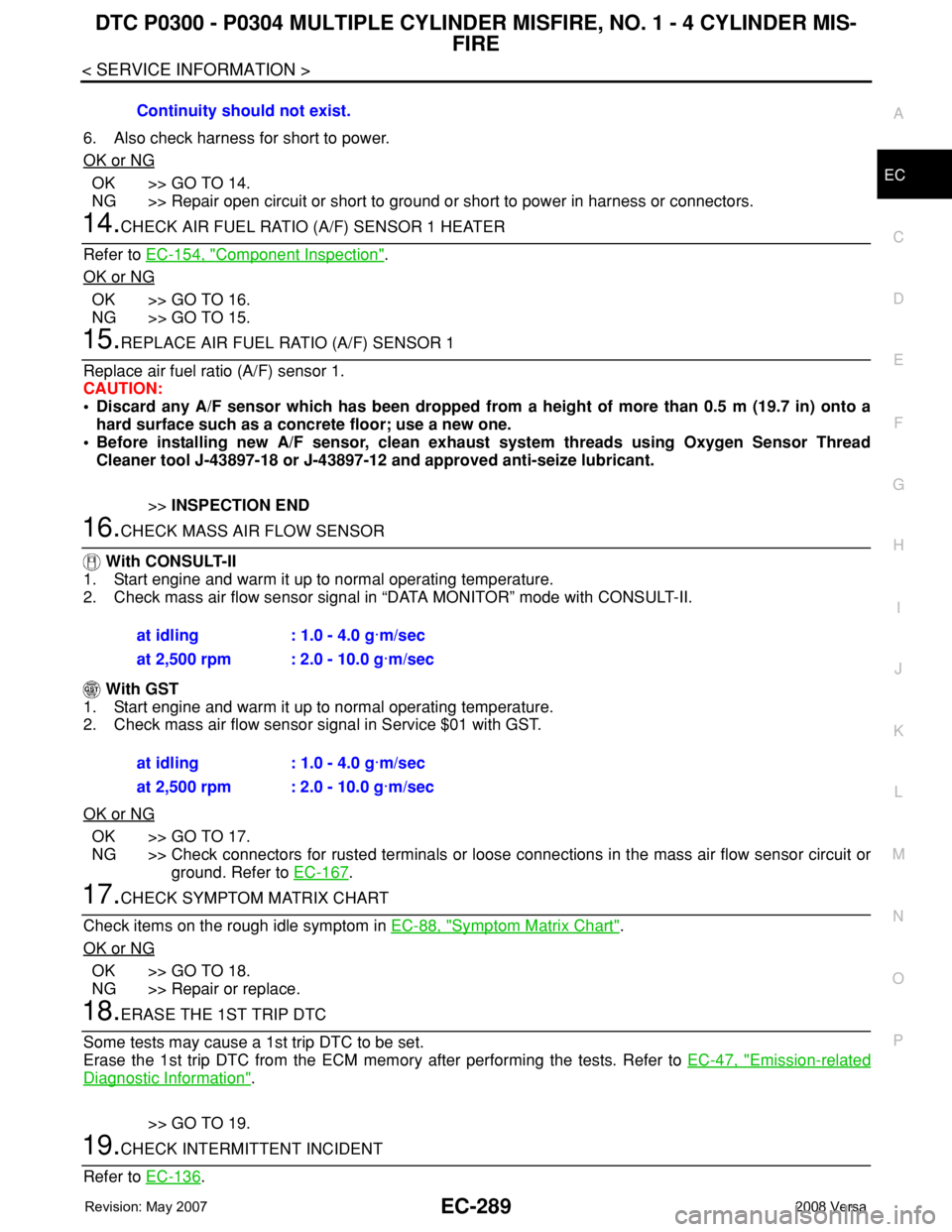
. Continuity should not exist.
at idling : 1.0 - 4.0 g·m/sec
at 2,500 rpm : 2.0 - 10.0 g·m/sec
at idling : 1.0 - 4.0 g·m/sec
at 2,500 rpm : 2.0 - 10.0 g·m/sec
Page 1579 of 2771
DTC P2A00 A/F SENSOR 1
EC-505
< SERVICE INFORMATION >
C
D
E
F
G
H
I
J
K
L
MA
EC
N
P O
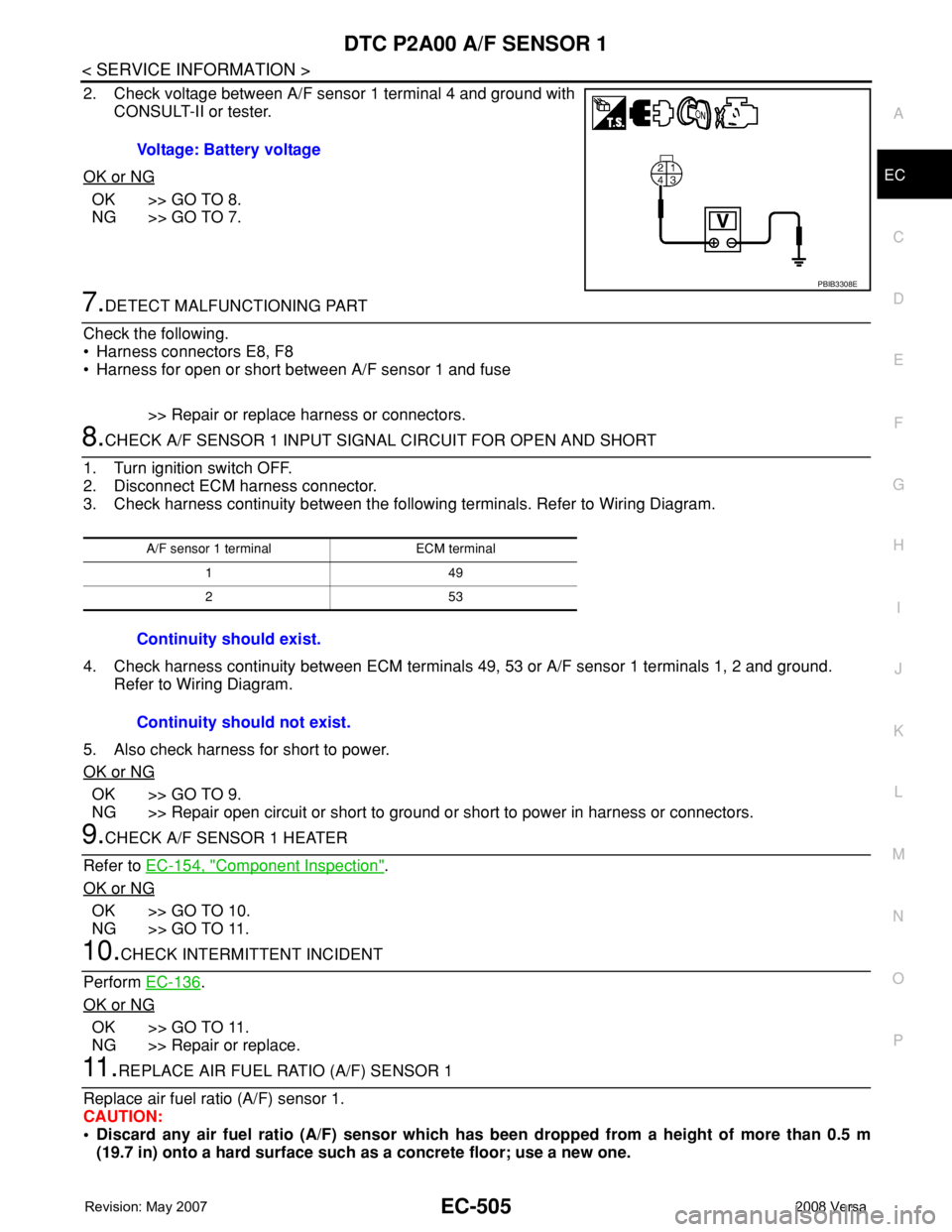
2. Check voltage between A/F sensor 1 terminal 4 and ground with
CONSULT-II or tester.
OK or NG
OK >> GO TO 8.
NG >> GO TO 7.
7.DETECT MALFUNCTIONING PART
Check the following.
• Harness connectors E8, F8
• Harness for open or short between A/F sensor 1 and fuse
>> Repair or replace harness or connectors.
8.CHECK A/F SENSOR 1 INPUT SIGNAL CIRCUIT FOR OPEN AND SHORT
1. Turn ignition switch OFF.
2. Disconnect ECM harness connector.
3. Check harness continuity between the following terminals. Refer to Wiring Diagram.
4. Check harness continuity between ECM terminals 49, 53 or A/F sensor 1 terminals 1, 2 and ground.
Refer to Wiring Diagram.
5. Also check harness for short to power.
OK or NG
OK >> GO TO 9.
NG >> Repair open circuit or short to ground or short to power in harness or connectors.
9.CHECK A/F SENSOR 1 HEATER
Refer to EC-154, "
Component Inspection".
OK or NG
OK >> GO TO 10.
NG >> GO TO 11.
10.CHECK INTERMITTENT INCIDENT
Perform EC-136
.
OK or NG
OK >> GO TO 11.
NG >> Repair or replace.
11 .REPLACE AIR FUEL RATIO (A/F) SENSOR 1
Replace air fuel ratio (A/F) sensor 1.
CAUTION:
• Discard any air fuel ratio (A/F) sensor which has been dropped from a height of more than 0.5 m
(19.7 in) onto a hard surface such as a concrete floor; use a new one. Voltage: Battery voltage
PBIB3308E
A/F sensor 1 terminal ECM terminal
149
253
Continuity should exist.
Continuity should not exist.
Page 1726 of 2771
CAMSHAFT
EM-49
< SERVICE INFORMATION >
C
D
E
F
G
H
I
J
K
L
MA
EM
N
P O
13. Remove valve lifters.
NOTE:
Identify installed positions, and store them without mixing them up.
INSPECTION AFTER REMOVAL
Camshaft Runout
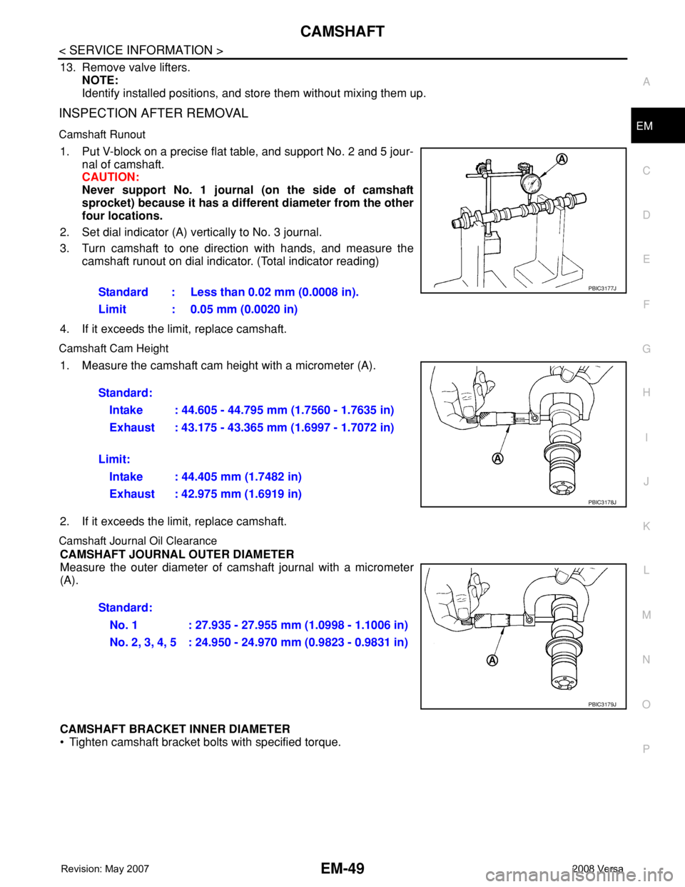
1. Put V-block on a precise flat table, and support No. 2 and 5 jour-
nal of camshaft.
CAUTION:
Never support No. 1 journal (on the side of camshaft
sprocket) because it has a different diameter from the other
four locations.
2. Set dial indicator (A) vertically to No. 3 journal.
3. Turn camshaft to one direction with hands, and measure the
camshaft runout on dial indicator. (Total indicator reading)
4. If it exceeds the limit, replace camshaft.
Camshaft Cam Height
1. Measure the camshaft cam height with a micrometer (A).
2. If it exceeds the limit, replace camshaft.
Camshaft Journal Oil Clearance
CAMSHAFT JOURNAL OUTER DIAMETER
Measure the outer diameter of camshaft journal with a micrometer
(A).
CAMSHAFT BRACKET INNER DIAMETER
• Tighten camshaft bracket bolts with specified torque. Standard : Less than 0.02 mm (0.0008 in).
Limit : 0.05 mm (0.0020 in)
PBIC3177J
Standard:
Intake : 44.605 - 44.795 mm (1.7560 - 1.7635 in)
Exhaust : 43.175 - 43.365 mm (1.6997 - 1.7072 in)
Limit:
Intake : 44.405 mm (1.7482 in)
Exhaust : 42.975 mm (1.6919 in)
PBIC3178J
Standard:
No. 1 : 27.935 - 27.955 mm (1.0998 - 1.1006 in)
No. 2, 3, 4, 5 : 24.950 - 24.970 mm (0.9823 - 0.9831 in)
PBIC3179J
Page 1736 of 2771
OIL SEAL
EM-59
< SERVICE INFORMATION >
C
D
E
F
G
H
I
J
K
L
MA
EM
N
P O
OIL SEAL
Removal and Installation of Valve Oil SealINFOID:0000000001702498
REMOVAL
1. Remove camshafts. Refer to EM-47, "Component".
2. Remove valve lifters. Refer to EM-47
.
3. Rotate crankshaft, and set piston whose valve oil seal is to be removed to TDC. This will prevent valve
from dropping into cylinder.
CAUTION:
When rotating crankshaft, be careful to avoid scarring front cover with timing chain.
4. Remove valve collet.
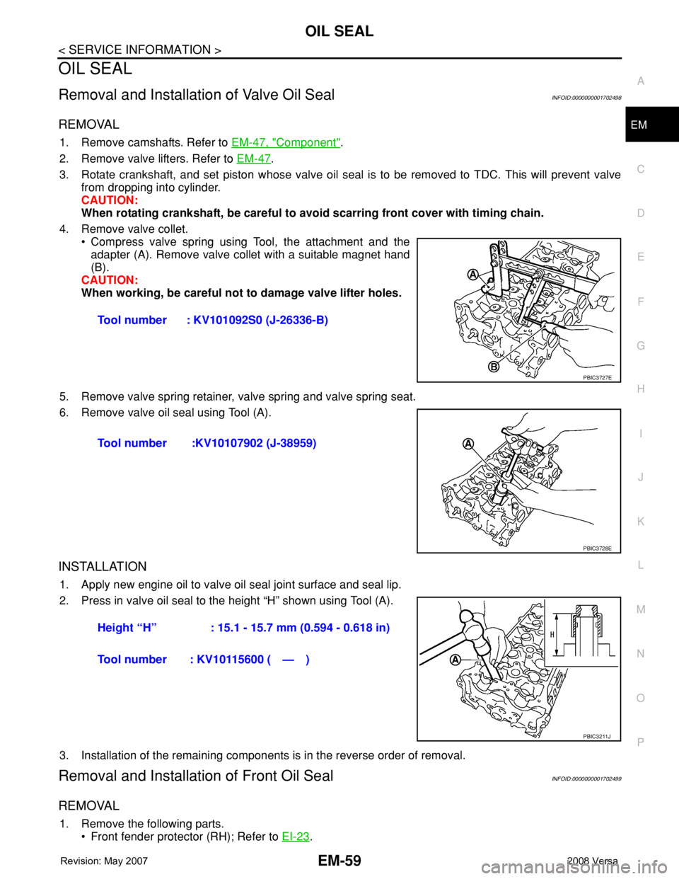
• Compress valve spring using Tool, the attachment and the
adapter (A). Remove valve collet with a suitable magnet hand
(B).
CAUTION:
When working, be careful not to damage valve lifter holes.
5. Remove valve spring retainer, valve spring and valve spring seat.
6. Remove valve oil seal using Tool (A).
INSTALLATION
1. Apply new engine oil to valve oil seal joint surface and seal lip.
2. Press in valve oil seal to the height “H” shown using Tool (A).
3. Installation of the remaining components is in the reverse order of removal.
Removal and Installation of Front Oil SealINFOID:0000000001702499
REMOVAL
1. Remove the following parts.
• Front fender protector (RH); Refer to EI-23
. Tool number : KV101092S0 (J-26336-B)
PBIC3727E
Tool number :KV10107902 (J-38959)
PBIC3728E
Height “H” : 15.1 - 15.7 mm (0.594 - 0.618 in)
Tool number : KV10115600 ( — )
PBIC3211J
Page 1744 of 2771
CYLINDER HEAD
EM-67
< SERVICE INFORMATION >
C
D
E
F
G
H
I
J
K
L
MA
EM
N
P O
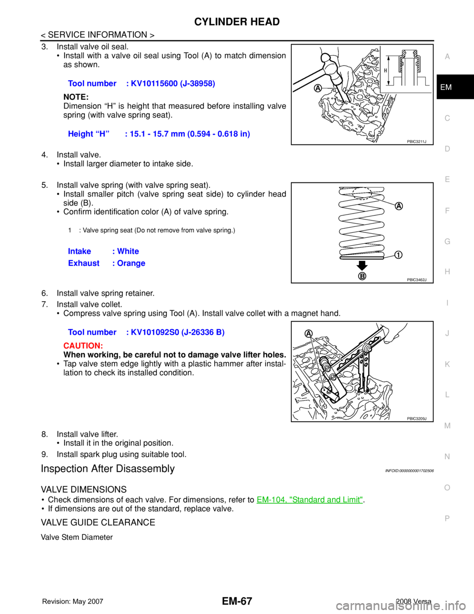
3. Install valve oil seal.
• Install with a valve oil seal using Tool (A) to match dimension
as shown.
NOTE:
Dimension “H” is height that measured before installing valve
spring (with valve spring seat).
4. Install valve.
• Install larger diameter to intake side.
5. Install valve spring (with valve spring seat).
• Install smaller pitch (valve spring seat side) to cylinder head
side (B).
• Confirm identification color (A) of valve spring.
6. Install valve spring retainer.
7. Install valve collet.
• Compress valve spring using Tool (A). Install valve collet with a magnet hand.
CAUTION:
When working, be careful not to damage valve lifter holes.
• Tap valve stem edge lightly with a plastic hammer after instal-
lation to check its installed condition.
8. Install valve lifter.
• Install it in the original position.
9. Install spark plug using suitable tool.
Inspection After DisassemblyINFOID:0000000001702506
VALVE DIMENSIONS
• Check dimensions of each valve. For dimensions, refer to EM-104, "Standard and Limit".
• If dimensions are out of the standard, replace valve.
VALVE GUIDE CLEARANCE
Valve Stem Diameter
Tool number : KV10115600 (J-38958)
Height “H” : 15.1 - 15.7 mm (0.594 - 0.618 in)
PBIC3211J
1 : Valve spring seat (Do not remove from valve spring.)
Intake : White
Exhaust : Orange
PBIC3462J
Tool number : KV101092S0 (J-26336 B)
PBIC3209J
Page 1748 of 2771
CYLINDER HEAD
EM-71
< SERVICE INFORMATION >
C
D
E
F
G
H
I
J
K
L
MA
EM
N
P O
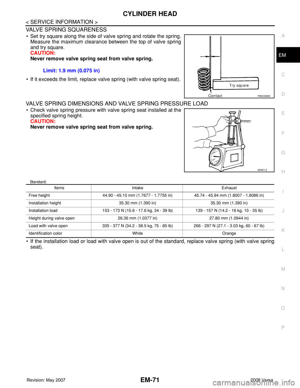
VALVE SPRING SQUARENESS
• Set try square along the side of valve spring and rotate the spring.
Measure the maximum clearance between the top of valve spring
and try square.
CAUTION:
Never remove valve spring seat from valve spring.
• If it exceeds the limit, replace valve spring (with valve spring seat).
VALVE SPRING DIMENSIONS AND VALVE SPRING PRESSURE LOAD
• Check valve spring pressure with valve spring seat installed at the
specified spring height.
CAUTION:
Never remove valve spring seat from valve spring.
Standard:
• If the installation load or load with valve open is out of the standard, replace valve spring (with valve spring
seat).Limit: 1.9 mm (0.075 in)
PBIC0080E
SEM113
Items Intake Exhaust
Free height 44.90 - 45.10 mm (1.7677 - 1.7755 in) 45.74 - 45.94 mm (1.8007 - 1.8086 in)
Installation height 35.30 mm (1.390 in) 35.30 mm (1.390 in)
Installation load 153 - 173 N (15.6 - 17.6 kg, 34 - 39 lb) 139 - 157 N (14.2 - 16 kg, 10 - 35 lb)
Height during valve open 26.36 mm (1.0377 in) 27.80 mm (1.0944 in)
Load with valve open 335 - 377 N (34.2 - 38.5 kg, 75 - 85 lb) 266 - 297 N (27.1 - 3.03 kg, 60 - 67 lb)
Identification color White Orange
Page 1778 of 2771
CYLINDER BLOCK
EM-101
< SERVICE INFORMATION >
C
D
E
F
G
H
I
J
K
L
MA
EM
N
P O
• If clearance exceeds the limit, select proper main bearing according to main bearing inner diameter and
crankshaft main journal diameter to obtain specified bearing oil clearance. Refer to EM-85, "
How to Select
Piston and Bearing".
Method of Using Plastigage
• Remove engine oil and dust on crankshaft main journal and the surfaces of each bearing completely.
• Cut a plastigage slightly shorter than the bearing width, and place it in crankshaft axial direction, avoiding oil
holes.
• Install main bearings to cylinder block and main bearing cap, and tighten main bearing cap bolts to the spec-
ified torque. Refer to EM-77, "
Disassembly and Assembly" for the tightening procedure.
CAUTION:
Never rotate crankshaft.
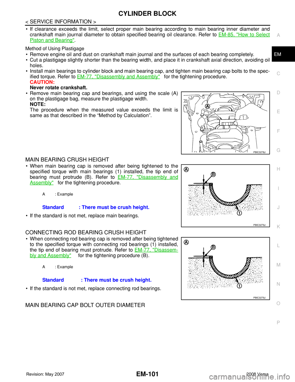
• Remove main bearing cap and bearings, and using the scale (A)
on the plastigage bag, measure the plastigage width.
NOTE:
The procedure when the measured value exceeds the limit is
same as that described in the “Method by Calculation”.
MAIN BEARING CRUSH HEIGHT
• When main bearing cap is removed after being tightened to the
specified torque with main bearings (1) installed, the tip end of
bearing must protrude (B). Refer to EM-77, "
Disassembly and
Assembly" for the tightening procedure.
• If the standard is not met, replace main bearings.
CONNECTING ROD BEARING CRUSH HEIGHT
• When connecting rod bearing cap is removed after being tightened
to the specified torque with connecting rod bearings (1) installed,
the tip end of bearing must protrude. Refer to EM-77, "
Disassem-
bly and Assembly" for the tightening procedure (B).
• If the standard is not met, replace connecting rod bearings.
MAIN BEARING CAP BOLT OUTER DIAMETER
PBIC3278J
A : Example
Standard : There must be crush height.
PBIC3279J
A : Example
Standard : There must be crush height.
PBIC3279J
Page 1782 of 2771
SERVICE DATA AND SPECIFICATIONS (SDS)
EM-105
< SERVICE INFORMATION >
C
D
E
F
G
H
I
J
K
L
MA
EM
N
P O
Unit: mm (in)
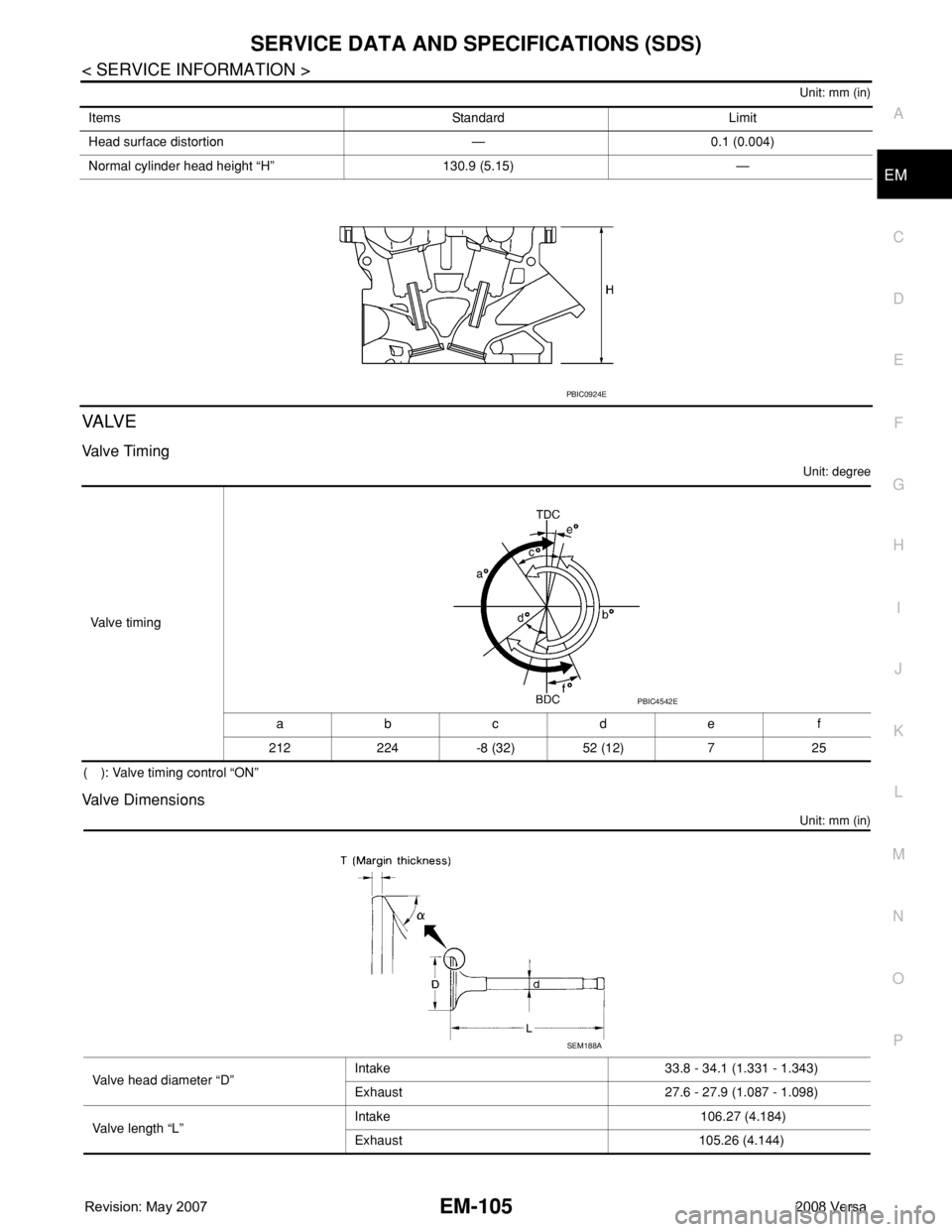
VA LV E
Va l v e Ti m i n g
Unit: degree
( ): Valve timing control “ON”
Valve Dimensions
Unit: mm (in)
Items Standard Limit
Head surface distortion — 0.1 (0.004)
Normal cylinder head height “H” 130.9 (5.15) —
PBIC0924E
Valve timing
abcde f
212 224 -8 (32) 52 (12) 7 25
PBIC4542E
Valve head diameter “D”Intake 33.8 - 34.1 (1.331 - 1.343)
Exhaust 27.6 - 27.9 (1.087 - 1.098)
Valve length “L”Intake 106.27 (4.184)
Exhaust 105.26 (4.144)
SEM188A