Page 2172 of 2771
HEADLAMP (FOR CANADA) - DAYTIME LIGHT SYSTEM -
LT-35
< SERVICE INFORMATION >
C
D
E
F
G
H
I
J
L
MA
B
LT
N
O
P
Aiming AdjustmentINFOID:0000000001704393
PREPARATION BEFORE ADJUSTING
Before performing aiming adjustment, check the following.
1. Keep all tires inflated to correct pressures.
2. Place vehicle on level surface.
3. Set that there is no-load in vehicle other than the driver (or equivalent weight placed in driver's position).
Coolant, engine oil filled up to correct level and full fuel tank, spare tire, jack and tools are properly
stowed.
LOW BEAM AND HIGH BEAM
1. Turn headlamp low beam ON.
2. Use adjusting screw to perform aiming adjustment.
3. Insert the tool through the adjusting screw access hole to avoid damage to the adjusting screw.
ADJUSTMENT USING AN ADJUSTMENT SCREEN (LIGHT/DARK BORDERLINE)
1. Headlamp A. Inner and outer adjustment B. Adjusting screw access hole
C. Adjusting screw
LKIA0930E
Page 2183 of 2771

LT-46
< SERVICE INFORMATION >
FRONT FOG LAMP
1. Check continuity between front fog lamp harness connector and
ground.
OK or NG
OK >> Replace IPDM E/R. Refer to PG-26, "Removal and
Installation of IPDM E/R" .
NG >> Repair harness or connector.
Aiming AdjustmentINFOID:0000000001704409
The front fog lamp is a semi-sealed beam type which uses a replaceable halogen bulb. Before performing
aiming adjustment, make sure of the following.
• Keep all tires inflated to correct pressure.
• Place vehicle on level surface.
• Set that there is no-load in vehicle other than the driver (or equivalent weight placed in driver’s position).
Coolant, engine oil filled up to correct level and full fuel tank, spare tire, jack and tools are properly stowed.
Adjust aiming in the vertical direction by turning the adjusting screw (A).
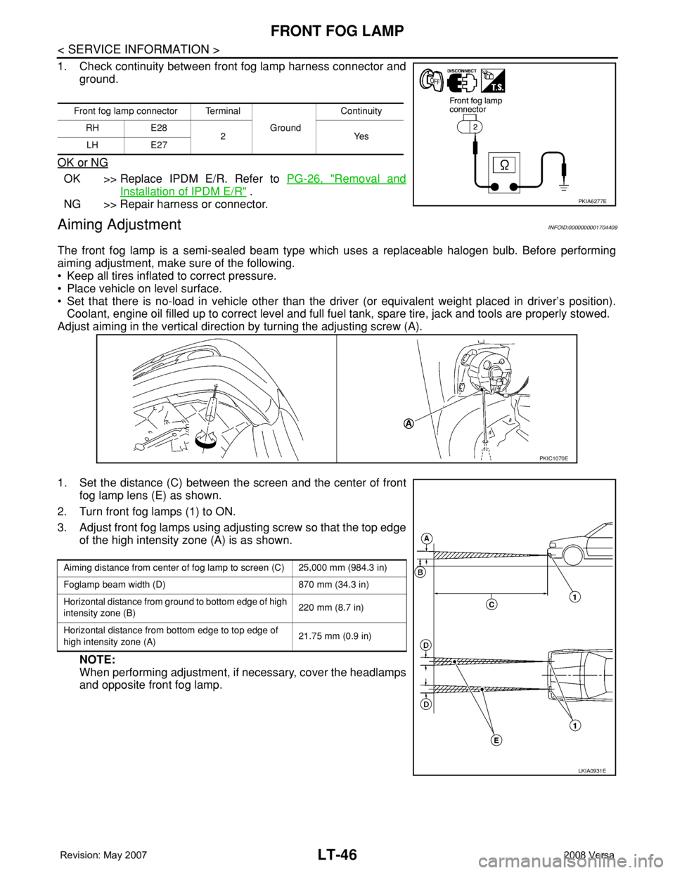
1. Set the distance (C) between the screen and the center of front
fog lamp lens (E) as shown.
2. Turn front fog lamps (1) to ON.
3. Adjust front fog lamps using adjusting screw so that the top edge
of the high intensity zone (A) is as shown.
NOTE:
When performing adjustment, if necessary, cover the headlamps
and opposite front fog lamp.
Front fog lamp connector Terminal
Ground Continuity
RH E28
2Yes
LH E27
PKIA6277E
PKIC1070E
Aiming distance from center of fog lamp to screen (C) 25,000 mm (984.3 in)
Foglamp beam width (D) 870 mm (34.3 in)
Horizontal distance from ground to bottom edge of high
intensity zone (B)220 mm (8.7 in)
Horizontal distance from bottom edge to top edge of
high intensity zone (A)21.75 mm (0.9 in)
LKIA0931E
Page 2274 of 2771

MA-14
< SERVICE INFORMATION >
ENGINE MAINTENANCE
1. Install reservoir tank if removed. Refer to CO-11 .
2. Install radiator drain plug.
•If water drain plug on cylinder block is removed, close and tighten it. Refer to EM-76
.
CAUTION:
Be sure to clean radiator drain plug and install with new O-ring. Refer to CO-11, "
Component" .
3. Fill radiator and reservoir tank with water and reinstall radiator cap.
4. Run engine and warm it up to normal operating temperature.
5. Rev engine two or three times under no-load.
6. Stop engine and wait until it cools down.
7. Drain water from the cooling system. Refer to "DRAINING ENGINE COOLANT" .
8. Repeat steps 1 through 7 until clear water begins to drain from radiator.
InspectionINFOID:0000000001704732
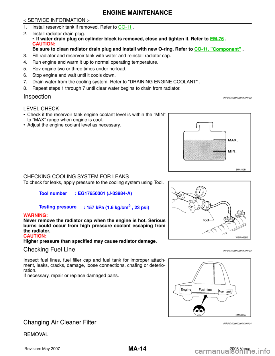
LEVEL CHECK
• Check if the reservoir tank engine coolant level is within the “MIN”
to “MAX” range when engine is cool.
• Adjust the engine coolant level as necessary.
CHECKING COOLING SYSTEM FOR LEAKS
To check for leaks, apply pressure to the cooling system using Tool.
WARNING:
Never remove the radiator cap when the engine is hot. Serious
burns could occur from high pressure coolant escaping from
the radiator.
CAUTION:
Higher pressure than specified may cause radiator damage.
Checking Fuel LineINFOID:0000000001704733
Inspect fuel lines, fuel filler cap and fuel tank for improper attach-
ment, leaks, cracks, damage, loose connections, chafing or deterio-
ration.
If necessary, repair or replace damaged parts.
Changing Air Cleaner FilterINFOID:0000000001704734
REMOVAL
SMA412B
Tool number : EG17650301 (J-33984-A)
Testing pressure
: 157 kPa (1.6 kg/cm
2 , 23 psi)
WBIA0568E
SMA803A
Page 2278 of 2771
MA-18
< SERVICE INFORMATION >
ENGINE MAINTENANCE
• Never use wire brush for cleaning spark plug.
INSTALLATION
1. Install spark plug using suitable tool.
CAUTION:
Never drop or shock spark plug.
2. Install ignition coil.
CAUTION:
• Handle ignition coil carefully and avoid impacts.
• Never disassemble ignition coil.
3. Install intake manifold. Refer to EM-18
.
Checking EVAP Vapor LineINFOID:0000000001704738
1. Visually inspect EVAP vapor lines for improper attachment and for cracks, damage, loose connections,
chafing and deterioration.
2. Inspect fuel tank filler cap vacuum relief valve for clogging, sticking, etc.
Refer to "Checking EVAP Vapor Lines"Cleaner air pressure
: Less than 588 kPa (5.88 bar, 6 kg/cm
2, 85 psi)
Cleaning time : Less than 20 seconds
SMA773C
Plug type : Iridium tipped
Make : DENSO
Part number : FXE20HR11
Gap (nominal) : 1.1 mm (0.043 in)
PBIC3871E
Page 2457 of 2771

PG-24
< SERVICE INFORMATION >
IPDM E/R (INTELLIGENT POWER DISTRIBUTION MODULE ENGINE ROOM)
24 Y Cooling fan relay-3 Output —Conditions correct for cooling
fan high operationBattery voltage
Conditions not correct for
cooling fan high operation0V
26 OTail lamp relay (park-
ing lamps)Output — Lighting switch in 2nd position Battery voltage
27 BRTail lamp relay (park-
ing lamps)Output — Lighting switch in 2nd position Battery voltage
28 GRTail lamp relay (park-
ing lamps)Output — Lighting switch in 2nd position Battery voltage
29 PTail lamp relay (park-
ing lamps)Output — Lighting switch in 2nd position Battery voltage
30
(A/T
only)R Fuse 54 Output —Ignition switch ON or START Battery voltage
Ignition switch OFF or ACC 0V
31 O Fuse 55 Output —Ignition switch ON or START Battery voltage
Ignition switch OFF or ACC 0V
32 LWiper high speed sig-
nalOutputON or
STARTWiper switchOFF, LO, INT 0V
HI Battery voltage
33 YWiper low speed sig-
nalOutputON or
STARTWiper switchOFF 0V
LO or INT Battery voltage
35 BRStarter relay (inhibit
switch)InputON or
STARTSelector lever in "P" or "N"
(CVT or A/T) or clutch pedal
depressed (M/T)Battery voltage
Selector lever any other posi-
tion (CVT or A/T) or clutch
pedal released (M/T)0V
36 BR Fuel pump relay Output —Ignition switch ON or START Battery voltage
Ignition switch OFF or ACC 0V
37 G Oil pressure switch InputON or
STARTEngine running and oil pres-
sure within specificationBattery voltage
Engine not running or oil pres-
sure below specification0V
38 R Wiper auto stop signal InputON or
STARTWipers not in park position Battery voltage
Wipers in park position 0V
39 B Ground Input — — 0V
40 P CAN-L — ON — —
41 L CAN-H — ON — —
45 R Horn relay control Input —Horn switch PUSHED, alarm
switch activated or door lock/
unlock is confirmed when op-
erating lock system via the
keyfob0V
Horn switch released, alarm
not active, keyfob not activeBattery voltage
46 YThrottle control motor
relay controlInput —Ignition switch ON or START 0V
Ignition switch OFF or ACC Battery voltage
47 GRFuel pump relay con-
trolInput —
Ignition switch ON or START 0V
Ignition switch OFF or ACC Battery voltage Te r m i n a lWire
colorSignal nameSignal
input/
outputMeasuring condition
Reference value
(Approx.) Ignition
switchOperation or condition
Page 2478 of 2771

HARNESS
PG-45
< SERVICE INFORMATION >
C
D
E
F
G
H
I
J
L
MA
B
PG
N
O
P
BODY HARNESS (HATCHBACK)
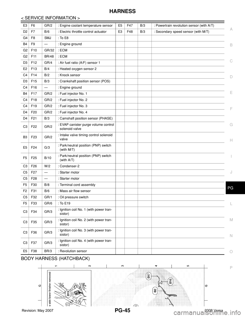
E3 F6 GR/2 : Engine coolant temperature sensor E5 F47 B/3 : Powertrain revolution sensor (with A/T)
D2 F7 B/6 : Electric throttle control actuatorE3 F48 B/3 : Secondary speed sensor (with M/T)
G4 F8 SMJ : To E8
B4 F9 — : Engine ground
G2 F10 GR/32 : ECM
G2 F11 BR/48 : ECM
D3 F12 GR/4 : Air fuel ratio (A/F) sensor 1
E2 F13 B/4 : Heated oxygen sensor 2
C4 F14 B/2 : Knock sensor
D3 F15 B/3 : Crankshaft position sensor (POS)
C4 F16 — : Engine ground
B4 F17 GR/2 : Fuel injector No. 1
C4 F18 GR/2 : Fuel injector No. 2
C4 F19 GR/2 : Fuel injector No. 3
D4 F20 GR/2 : Fuel injector No. 4
D4 F21 B/3 : Camshaft position sensor (PHASE)
C3 F22 GR/2: EVAP canister purge volume control
solenoid valve
B3 F23 GR/2: Intake valve timing control solenoid
valve
E5 F24 G/3: Park/neutral position (PNP) switch
(with M/T)
F5 F25 B/10: Park/neutral position (PNP) switch
(with A/T)
C3 F26 W/2 : Condenser-2
C5 F27 — : Starter motor
C5 F28 — : Starter motor
F5 F30 B/8 : Terminal cord assembly
F2 F31 B/6 : Mass air flow sensor
C5 F32 GR/1 : Oil pressure switch
F5 F33 GR/6 : To E19
C3 F34 GR/3: Ignition coil No. 1 (with power tran-
sistor)
C3 F35 GR/3: Ignition coil No. 2 (with power tran-
sistor)
C3 F36 GR/3: Ignition coil No. 3 (with power tran-
sistor)
C3 F37 GR/3: Ignition coil No. 4 (with power tran-
sistor)
E5 F38 BR/3 : Revolution sensor
Page 2482 of 2771
HARNESS
PG-49
< SERVICE INFORMATION >
C
D
E
F
G
H
I
J
L
MA
B
PG
N
O
P
BODY NO. 2 HARNESS (HATCHBACK)
LKIA0819E
D3 B100 GR/5 : Fuel level sensor unit and fuel pump
G5 B101 W/16 : To M12
G5 B102 W/24 : To M13
F3 B103 B/2 : Console power socket
A4 B104 GR/3: EVAP control system pressure sen-
sor
Page 2484 of 2771

HARNESS
PG-51
< SERVICE INFORMATION >
C
D
E
F
G
H
I
J
L
MA
B
PG
N
O
P
E3 B100 GR/5 : Fuel level sensor unit and fuel pump
G5 B101 W/16 : To M12
G5 B102 W/24 : To M13
F4 B103 B/2 : Console power socket
B4 B104 GR/3: EVAP control system pressure sen-
sor
B3 B105 B/2 : EVAP canister vent control valve
G5 B106 W/4 : To M11
A2 B107 BR/6 : Rear combination lamp RH
F4 B108 W/3 : Front door switch RH
F4 B109 Y/2 : Front RH side air bag module
F4 B110 W/10 : To B300
E5 B111 Y/2 : RH side air bag (satellite) sensor
F4 B112 W/3 : Seat belt buckle switch RH
G3 B113 Y/12 : Air bag diagnosis sensor unit
E4 B114 — : Body ground
E4 B115 Y/2 : Front RH seat belt pre-tensioner
C3 B116 W/1 : Rear door switch RH
E3 B117 — : Body ground
C2 B118 Y/2 : RH side curtain air bag module
E4 B119 W/8 : To D301
G5 B120 W/24 : To M14
C3 B121 W/32 : Bluetooth control unit
B3 B122 GR/1 : Bluetooth control unit
E3 B123 B/2 : Rear wheel sensor LH
D4 B124 B/2 : Rear wheel sensor RH
F4 B125 GR/2 : Front console antenna
D3 B126 GR/2 : Rear floor antenna
B2 B127 W/3: Trunk lamp switch and trunk release
solenoid
B1 B128 BR/2 : Trunk lid opener switch
B1 B129 GR/2 : Trunk opener request switch
C2 B130 B/1 : Condenser-1
C2 B131 B/1 : Condenser-1
C3 B132 — : Body ground
E5 B138 B/3 : Belt tension sensor
D1 B139 — : Body ground
C2 B140 B/1 : Rear window defogger (+)
D1 B141 B/1 : Rear window defogger (-)
B2 B142 W/3 : Trunk key cylinder switch
B1 B143 BR/2 : License plate lamp RH
B2 B144 BR/2 : License plate lamp LH