Page 43 of 352

Top Tether Anchor Point Locations
Anchor points are located in the following loca-
tions:
cOn the back of the front passenger seat
(King cab only) .
cOn the floor between the jump seat belt
buckles in the center of the vehicle (King cab
only) .
cUnder the rear window behind the rear
bench seat (Crew cab only) .
If you have any questions when installing a
top tether strap child restraint on the front
passenger’s seat, rear passenger’s side
jump seat or rear bench seat, consult your
NISSAN dealer for details.
Installing top tether strap
First, secure the child restraint with the LATCH
system (rear bench outboard seating positions
on Crew cab only) or the seat belt, as applicable.Front passenger seat (King cab models
only)
1. Top tether strap
2. Top tether strap anchor point
For the front passenger seat in the King cab only,
install the top tether strap as follows:
1. Adjust the head restraint to its highest posi-
tion.
2. Route the top tether strap between the head
restraint and the top of the seatback.
3. Secure the tether strap to the tether anchor
point on the seatback.4. Tighten the tether strap according to the
manufacturer’s instructions to remove any
slack.
For best child restraint fit, see the child restraint
installation instructions in this section and the
child restraint manufacturer’s instructions.
LRS0572
Safety—Seats, seat belts and supplemental restraint system1-25
ZREVIEW COPYÐ2008 08+ Truck/Frontier(fro)
Owners ManualÐUSA_English(nna)
06/30/07Ðdebbie
X
Page 248 of 352

WARNING
Always follow the instructions below.
Failure to do so could result in damage to
the charging system and cause personal
injury.
1. If the booster battery is in another vehicle,
position the two vehicles to bring their bat-
teries near each other.
Do not allow the two vehicles to touch.2. Apply the parking brake. Move the shift lever
to N (Neutral) (manual transmission) or to P
(Park) (automatic transmission) . Switch off
all unnecessary electrical systems (lights,
heater, air conditioner, etc.) .
3. Remove vent caps on the battery (if so
equipped) . Cover the battery with an old
cloth to reduce explosion hazard.
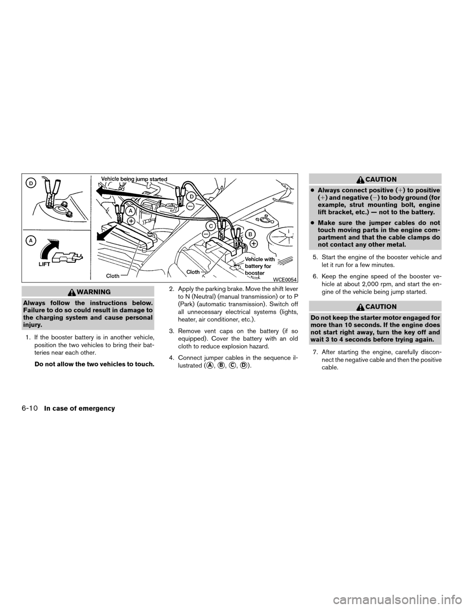
4. Connect jumper cables in the sequence il-
lustrated (
sA,sB,sC,sD).
CAUTION
cAlways connect positive (1) to positive
(1) and negative (2) to body ground (for
example, strut mounting bolt, engine
lift bracket, etc.) — not to the battery.
cMake sure the jumper cables do not
touch moving parts in the engine com-
partment and that the cable clamps do
not contact any other metal.
5. Start the engine of the booster vehicle and
let it run for a few minutes.
6. Keep the engine speed of the booster ve-
hicle at about 2,000 rpm, and start the en-
gine of the vehicle being jump started.
CAUTION
Do not keep the starter motor engaged for
more than 10 seconds. If the engine does
not start right away, turn the key off and
wait 3 to 4 seconds before trying again.
7. After starting the engine, carefully discon-
nect the negative cable and then the positive
cable.
WCE0054
6-10In case of emergency
ZREVIEW COPYÐ2008 08+ Truck/Frontier(fro)
Owners ManualÐUSA_English(nna)
06/30/07Ðdebbie
X
Page 277 of 352

Vehicles operated in high temperatures or under
severe conditions require frequent checks of the
battery fluid level.
JUMP STARTING
If jump starting is necessary, see “Jump starting”
in the “In case of emergency” section of this
manual. If the engine does not start by jump
starting, the battery may have to be replaced.
Contact a NISSAN dealer.
CAUTION
cDo not ground accessories directly to
the battery terminal. Doing so will by-
pass the variable voltage control sys-
tem and the vehicle battery may not
charge completely.
cUse electrical accessories with the en-
gine running to avoid discharging the
vehicle battery.Your vehicle is equipped with a variable voltage
control system. This system measures the
amount of electrical discharge from the battery
and controls voltage generated by the generator.
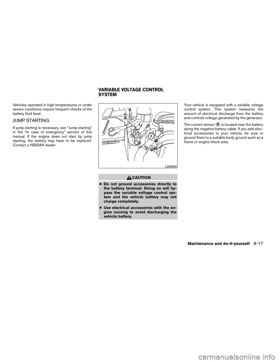
The current sensor
sAis located near the battery
along the negative battery cable. If you add elec-
trical accessories to your vehicle, be sure to
ground them to a suitable body ground such as a
frame or engine block area.
LDI0454
VARIABLE VOLTAGE CONTROL
SYSTEM
Maintenance and do-it-yourself8-17
ZREVIEW COPYÐ2008 08+ Truck/Frontier(fro)
Owners ManualÐUSA_English(nna)
06/30/07Ðdebbie
X