2008 NISSAN ARMADA Brake fuse
[x] Cancel search: Brake fusePage 14 of 456

1. Battery (P. 8-13)
2. Fuse/fusible link box (P. 8-22)
3. Transmission dipstick (P. 8-11)
4. Engine oil filler cap (P. 8-8)
5. Brake fluid reservoir (P. 8-12)
6. Windshield washer fluid reservoir
(P. 8-12)
7. Air cleaner (P. 8-17)
8. Drive belt location (P.8-15)
9. Radiator cap (P. 8-7)
10. Power steering fluid reservoir (P. 8-11)
11. Engine oil dipstick (P. 8-8)
12. Engine coolant reservoir (P. 8-7)
See the page number indicated in paren-
theses for operating details.
WDI0630
ENGINE COMPARTMENT CHECK
LOCATIONS
0-8Illustrated table of contents
ZREVIEW COPYÐ2008 Armada(wzw)
Owners ManualÐUSA_English(nna)
03/05/07Ðarosenma
X
Page 178 of 456

3. Adjust the driver’s seat, accelerator and
brake pedals, and outside mirrors to the
desired positions by manually operating
each adjusting switch. For additional infor-
mation, see “Seats” in the “Safety—Seats,
seat belts and supplemental restraint sys-
tem” section and “Pedal position adjust-
ment” and “Outside mirrors” earlier in this
section.
During this step, do not turn the ignition to
any position other than ON.
4. Push the SET switch and, within 5 seconds,
push the memory switch (1 or 2) fully for at
least 1 second.
The indicator light for the pushed memory
switch will come on and stay on for approxi-
mately 5 seconds after pushing the switch.
After the indicator light goes off, the se-
lected positions are stored in the selected
memory (1 or 2) .
If a new memory is stored in the same memory
switch, the previous memory will be deleted.
Linking a keyfob to a stored memory
position
Each keyfob can be linked to a stored memory
position (memory switch 1 or 2) with the follow-
ing procedure.1. Follow the steps for storing a memory posi-
tion.
2. While the indicator light for the memory
switch being set is illuminated for 5 sec-
onds, press the
button on the keyfob.
The indicator light will blink. After the indica-
tor light goes off, the keyfob is linked to that
memory setting.
With the key removed from the ignition switch,
press the
button on the keyfob. The driv-
er’s seat, accelerator and brake pedals, and out-
side mirrors will move to the memorized position.
NOTE:
If a new memory position is saved to the
memory switch, the keyfob automatically
re-links.
Confirming memory storage
cTurn the ignition ON and push the SET
switch. If the main memory has not been
stored, the indicator light will come on for
approximately 0.5 seconds. When the
memory has stored the position, the indica-
tor light will stay on for approximately 5 sec-
onds.
cIf the battery cable is disconnected, or if the
fuse opens, the memory storage function will
be canceled and must be restarted before astored memory position can be set again.
Drive the vehicle over 25 MPH (40 km/h) to
restart the memory storage function. You
can also restart the memory storage function
using the following procedure.
1. Connect the battery cable or replace the
fuse.
2. Open and close the driver’s door more than
two times with the ignition key in the LOCK
position.
Once the memory storage function has been
restarted, you can store a memory position.
See “Memory storage function” earlier in this
section.
Selecting the memorized position
Set the automatic transmission selector lever to
the P (Park) position, then:
cWithin 45 seconds of opening the driver’s
door, push the memory switch (1 or 2) fully
for at least 1 second, or
cTurn the ignition switch to the ON position
and push the memory switch (1 or 2) fully for
at least 1 second.
The driver’s seat, accelerator and brake pedals,
and outside mirrors will move to the memorized
position with the indicator light blinking, and then
the light will stay on for approximately 5 seconds.
3-32Pre-driving checks and adjustments
ZREVIEW COPYÐ2008 Armada(wzw)
Owners ManualÐUSA_English(nna)
03/05/07Ðarosenma
X
Page 369 of 456

8 Maintenance and do-it-yourself
Maintenance requirements..........................8-2
General maintenance..............................8-2
Explanation of general maintenance items.........8-2
Maintenance precautions...........................8-5
Engine compartment check locations................8-6
Engine cooling system.............................8-7
Checking engine coolant level...................8-7
Changing engine coolant........................8-8
Engine oil.........................................8-8
Checking engine oil level........................8-8
Changing engine oil............................8-9
Changing engine oil filter.......................8-10
5-speed automatic transmission fluid...............8-11
Power steering fluid...............................8-11
Brake fluid.......................................8-12
Brake fluid....................................8-12
Window washer fluid.............................8-12
Window washer fluid reservoir..................8-12
Battery..........................................8-13
Jump starting.................................8-14
Variable Voltage Control System...................8-15
Drive belt........................................8-15
Spark plugs......................................8-16Replacing spark plugs.........................8-16
Air cleaner.......................................8-17
In-cabin microfilter.............................8-17
Windshield wiper blades..........................8-19
Cleaning.....................................8-19
Replacing....................................8-19
Brakes..........................................8-22
Fuses...........................................8-22
Engine compartment...........................8-23
Passenger compartment.......................8-24
Battery replacement..............................8-26
Keyfob.......................................8-26
Intelligent Key battery..........................8-27
Lights...........................................8-28
Headlights....................................8-28
Fog lights (if so equipped)......................8-29
Exterior and interior lights.......................8-30
Wheels and tires.................................8-34
Tire pressure..................................8-34
Tire labeling...................................8-38
Types of tires..................................8-40
Tire chains....................................8-40
Changing wheels and tires.....................8-41
ZREVIEW COPYÐ2008 Armada(wzw)
Owners ManualÐUSA_English(nna)
03/05/07Ðarosenma
X
Page 374 of 456

1. Battery
2. Fuse/fusible link box
3. Transmission dipstick
4. Engine oil filler cap
5. Brake fluid reservoir
6. Windshield washer fluid reservoir
7. Air cleaner
8. Drive belt location
9. Radiator cap
10. Power steering fluid reservoir
11. Engine oil dipstick
12. Engine coolant reservoir
NOTE:
Engine cover removed for clarity.
WDI0630
ENGINE COMPARTMENT CHECK
LOCATIONS
8-6Maintenance and do-it-yourself
ZREVIEW COPYÐ2008 Armada(wzw)
Owners ManualÐUSA_English(nna)
03/05/07Ðarosenma
X
Page 390 of 456

If the brakes do not operate properly, have the
brakes checked by a NISSAN dealer.
Self-adjusting brakes
Your vehicle is equipped with self-adjusting
brakes.
The front and rear disc-type brakes self-adjust
every time the brake pedal is applied.
WARNING
See a NISSAN dealer for a brake system
check if the brake pedal height does not
return to normal.
Brake pad wear indicators
The disc brake pads on your vehicle have audible
wear indicators. When a brake pad requires re-
placement, a high pitched scraping or screech-
ing sound will be heard when the vehicle is in
motion. The noise will be heard whether or not the
brake pedal is depressed. Have the brakes
checked as soon as possible if the wear indicator
sound is heard.
Under some driving or climate conditions, occa-
sional brake squeak, squeal or other noise may
be heard. Occasional brake noise during light to
moderate stops is normal and does not affect the
function or performance of the brake system.Proper brake inspection intervals should
be followed.For more information regarding
brake inspections, see the appropriate mainte-
nance schedule information in the “NISSAN Ser-
vice and Maintenance Guide”.
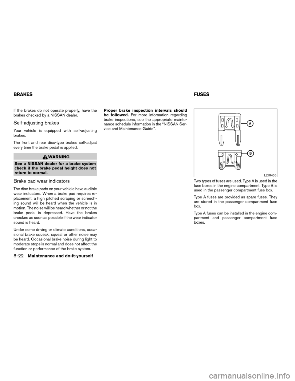
Two types of fuses are used. Type A is used in the
fuse boxes in the engine compartment. Type B is
used in the passenger compartment fuse box.
Type A fuses are provided as spare fuses. They
are stored in the passenger compartment fuse
box.
Type A fuses can be installed in the engine com-
partment and passenger compartment fuse
boxes.
LDI0455
BRAKESFUSES
8-22Maintenance and do-it-yourself
ZREVIEW COPYÐ2008 Armada(wzw)
Owners ManualÐUSA_English(nna)
03/05/07Ðarosenma
X
Page 437 of 456

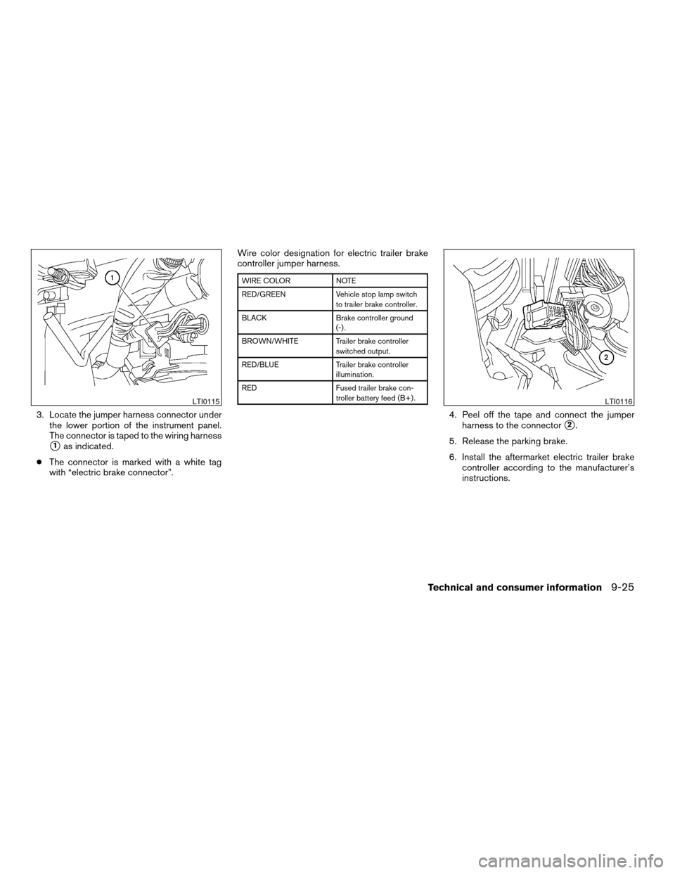
3. Locate the jumper harness connector under
the lower portion of the instrument panel.
The connector is taped to the wiring harness
s1as indicated.
cThe connector is marked with a white tag
with “electric brake connector”.Wire color designation for electric trailer brake
controller jumper harness.
WIRE COLOR NOTE
RED/GREEN Vehicle stop lamp switch
to trailer brake controller.
BLACK Brake controller ground
(-) .
BROWN/WHITE Trailer brake controller
switched output.
RED/BLUE Trailer brake controller
illumination.
RED Fused trailer brake con-
troller battery feed (B+) .
4. Peel off the tape and connect the jumper
harness to the connector
s2.
5. Release the parking brake.
6. Install the aftermarket electric trailer brake
controller according to the manufacturer’s
instructions.
LTI0115LTI0116
Technical and consumer information9-25
ZREVIEW COPYÐ2008 Armada(wzw)
Owners ManualÐUSA_English(nna)
03/05/07Ðarosenma
X
Page 449 of 456

Eyeglass case..................2-44
F
Flashers
(See hazard warning flasher switch)......2-36
Flat tire......................6-2
Floor mat positioning aid.............7-4
Fluid
Brake fluid..................8-12
Capacities and recommended
fuel/lubricants.................9-2
Engine coolant................8-7
Engine oil...................8-8
Power steering fluid.............8-11
Window washer fluid............8-12
F.M.V.S.S. certification label..........9-11
Fog light switch.................2-35
Front air bag system
(See supplemental restraint system).....1-55
Front seats....................1-2
Front sonar system............2-39, 5-31
Fuel
Capacities and recommended
fuel/lubricants.................9-2
Fuel economy................5-19
Fuel gauge..................2-7
Fuel octane rating..............9-4
Fuel recommendation............9-3
Fuel-filler door and cap...........3-25
Fuses......................8-22
Fusible links...................8-24G
Garage door opener, HomeLinkTUniversal
Transceiver...................2-60
Gascap.....................3-25
Gauge
Automatic transmission fluid temperature
gauge.....................2-8
Engine coolant temperature gauge.....2-6
Engine oil pressure gauge..........2-7
Fuel gauge..................2-7
Odometer...................2-5
Speedometer.................2-5
Tachometer..................2-6
Trip odometer.................2-5
Voltmeter...................2-8
General maintenance..............8-2
Glass hatch...................3-25
Glove box....................2-44
Glove box lock.................2-44
H
Hands-free phone system,
BluetoothT...............4-94, 4-108
Hazard warning flasher switch.........2-36
Head restraints..................1-8
Active Head Restraint............1-9
Headlight and turn signal switch........2-32
Headlight control switch............2-32
Headlights....................8-28
Headphones (See NISSAN mobile
entertainment system).............4-81
Heated seats..................2-37Heated steering wheel.............2-37
Heater
Heater and air conditioner controls. . . .4-38
Heater operation..............4-39
Rear seat air conditioner..........4-40
HomeLinkTUniversal Transceiver.......2-60
Hood release..................3-20
Hook
Luggage hook................2-50
Horn.......................2-36
I
Ignition switch..................5-8
Immobilizer system.........2-29, 3-3, 5-11
Important vehicle information label.......9-11
In-cabin microfilter...............8-17
Increasing fuel economy............5-19
Indicator lights and audible reminders
(See warning/indicator lights and audible
reminders)....................2-13
Inside automatic anti-glare mirror.......3-29
Instrument brightness control.........2-35
Instrument panel..............0-6, 2-2
Instrument panel dimmer switch........2-35
Intelligent Key system..............3-10
Key operating range............3-12
Key operation................3-13
Mechanical key................3-3
Remote keyless entry operation......3-16
Troubleshooting guide...........3-18
Warning signals...............3-18
Interior light...................2-58
ISOFIX child restraints.............1-28
10-3
ZREVIEW COPYÐ2008 Armada(wzw)
Owners ManualÐUSA_English(nna)
03/05/07Ðarosenma
X