Page 112 of 241
SENSOR
MULTIPORT FUEL SYSTEM (MFI)13A-19
.
POWER STEERING PRESSURE SWITCH
A power steering pressure switch is installed on the power
steering oil pump. The power steering pressure switch uses a
contact switch to detect the power steering oil pressure. When
power steering oil pressure rises due to operation of the steer
-
ing wheel, the power steering load switch outputs an ON signal
to ECM. ECM performs idle-up according to the voltage and
prevents reduction in engine speed due to power steering load
and so maintains stable idle speed.
.
AK602228
ON
OFF
AD
12
0ONOFF ECM terminal voltage V
Oil pressure:lowOil pressure: high Operating pressure
Oil pressure kPa (in.Hg) Engine oil
pressure switch
ECM
AK601174AF
Power steering
pressure switch
Oil
pressure
AK602213
ON
OFF
AE
Oil pressure:low
Oil pressure: highOperating pressure
Power steering
pressure switch12
0OFF
ON
ECM
ECM
terminal voltage V
Oil pressure kPa (in.Hg)
Page 118 of 241
ACTUATOR
MULTIPORT FUEL SYSTEM (MFI)13A-25
IGNITION COIL
Refer to GROUP 16 − Ignition Coil P.16-2.
EXHAUST GAS RECIRCULATION (EGR) VALVE
Refer to GROUP 17 − Emission Control − Exhaust Gas Recircu-
lation (EGR) System P.17-12.
EVAPORATIVE EMISSION PURGE SOLENOID
Refer to GROUP 17 − Emission Control − Evaporative Emission
Control System
P.17-11.
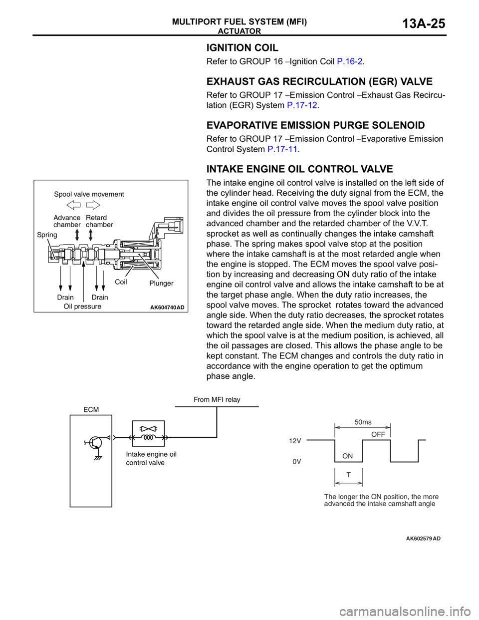
INTAKE ENGINE OIL CONTROL VALVE
The intake engine oil control valve is installed on the left side of
the cylinder head. Receiving the duty signal from the ECM, the
intake engine oil control valve moves the spool valve position
and divides the oil pressure from the cylinder block into the
advanced chamber and the retarded chamber of the V.V.T.
sprocket as well as continually changes the intake camshaft
phase. The spring makes spool valve stop at the position
where the intake camshaft is at the most retarded angle when
the engine is stopped. The ECM moves the spool valve posi
-
tion by increasing and decreasing ON duty ratio of the intake
engine oil control valve and allows the intake camshaft to be at
the target phase angle. When the duty ratio increases, the
spool valve moves. The sprocket rotates toward the advanced
angle side. When the duty ratio decreases, the sprocket rotates
toward the retarded angle side. When the medium duty ratio, at
which the spool valve is at the medium position, is achieved, all
the oil passages are closed. This allows the phase angle to be
kept constant. The ECM changes and controls the duty ratio in
accordance with the engine operation to get the optimum
phase angle.
AK604740AD
Spool valve movement
Retard
chamber
Spring
Drain
Oil pressureCoil
Plunger
Drain Advance
chamber
AK602579
ECM
Intake engine oil
control valve12VOFF
ON
T50ms
0V
AD
From MFI relay
The longer the ON position, the more
advanced the intake camshaft angle
Page 119 of 241
ACTUATOR
MULTIPORT FUEL SYSTEM (MFI)13A-26
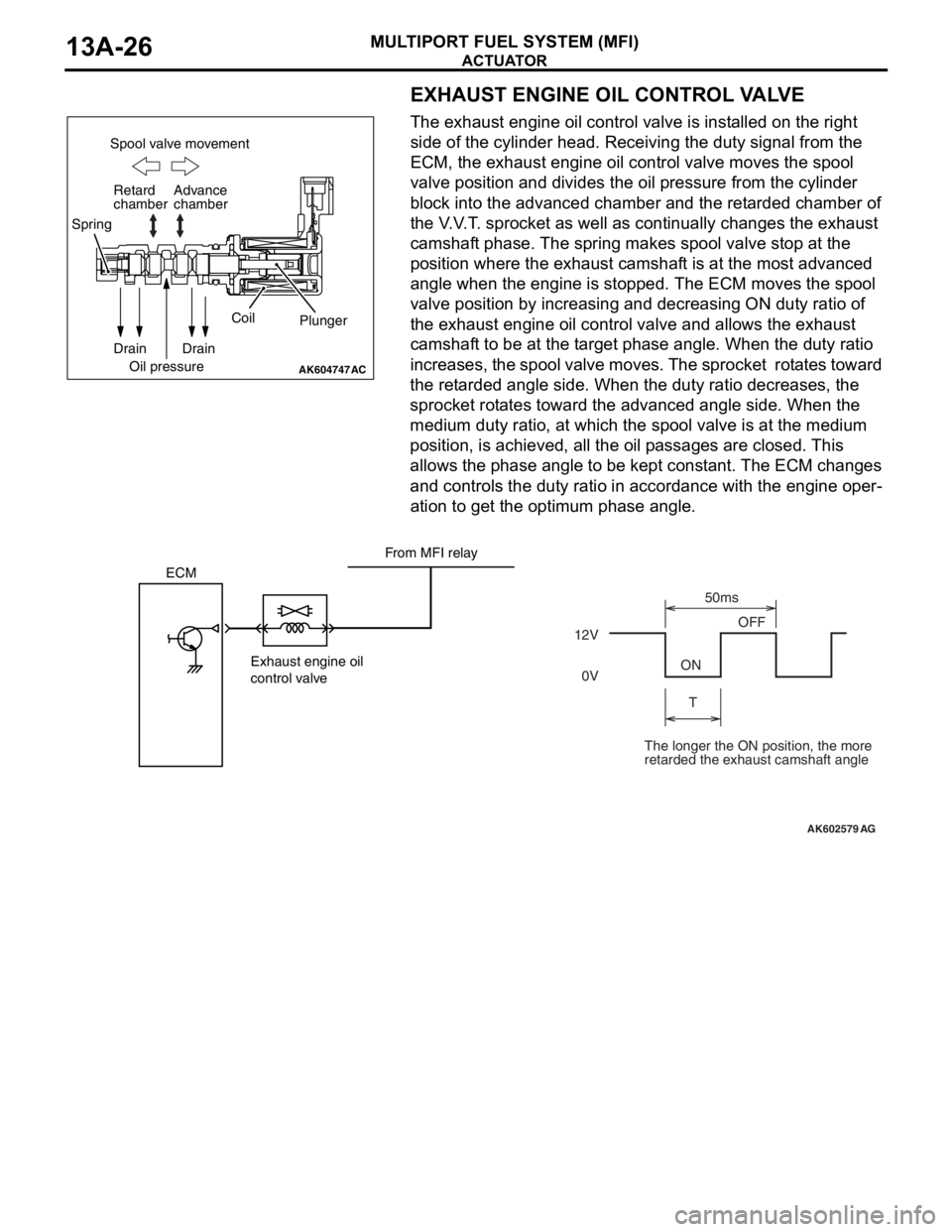
EXHAUST ENGINE OIL CONTROL VALVE
The exhaust engine oil control valve is installed on the right
side of the cylinder head. Receiving the duty signal from the
ECM, the exhaust engine oil control valve moves the spool
valve position and divides the oil pressure from the cylinder
block into the advanced chamber and the retarded chamber of
the V.V.T. sprocket as well as continually changes the exhaust
camshaft phase. The spring makes spool valve stop at the
position where the exhaust camshaft is at the most advanced
angle when the engine is stopped. The ECM moves the spool
valve position by increasing and decreasing ON duty ratio of
the exhaust engine oil control valve and allows the exhaust
camshaft to be at the target phase angle. When the duty ratio
increases, the spool valve moves. The sprocket rotates toward
the retarded angle side. When the duty ratio decreases, the
sprocket rotates toward the advanced angle side. When the
medium duty ratio, at which the spool valve is at the medium
position, is achieved, all the oil passages are closed. This
allows the phase angle to be kept constant. The ECM changes
and controls the duty ratio in accordance with the engine oper
-
ation to get the optimum phase angle.
AK604747
Spool valve movement
Retard
chamber
Spring
Drain
Oil pressureCoil
Plunger
Drain Advance
chamber
AC
AK602579
ECM
Exhaust engine oil
control valve12VOFF
ON
T50ms
0V
AG
From MFI relay
The longer the ON position, the more
retarded the exhaust camshaft angle
Page 120 of 241
ACTUATOR
MULTIPORT FUEL SYSTEM (MFI)13A-27
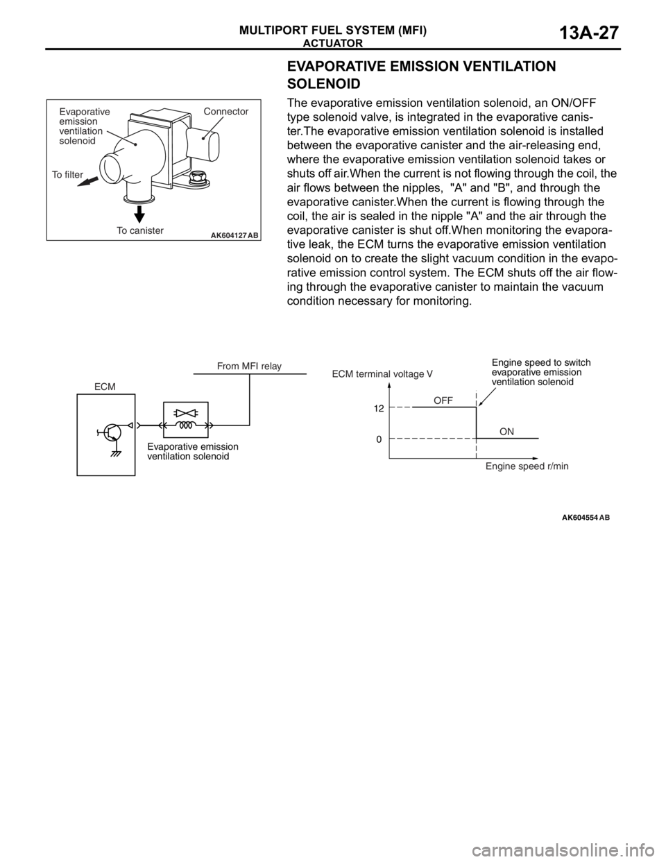
EVAPORATIVE EMISSION VENTILATION
SOLENOID
The evaporative emission ventilation solenoid, an ON/OFF
type solenoid valve, is integrated in the evaporative canis
-
ter.The evaporative emission ventilation solenoid is installed
between the evaporative canister and the air-releasing end,
where the evaporative emission ventilation solenoid takes or
shuts off air.When the current is not flowing through the coil, the
air flows between the nipples, "A" and "B", and through the
evaporative canister.When the current is flowing through the
coil, the air is sealed in the nipple "A" and the air through the
evaporative canister is shut off.When monitoring the evapora
-
tive leak, the ECM turns the evaporative emission ventilation
solenoid on to create the slight vacuum condition in the evapo
-
rative emission control system. The ECM shuts off the air flow-
ing through the evaporative canister to maintain the vacuum
condition necessary for monitoring.
AK604127ABTo canisterConnector
Evaporative
emission
ventilation
solenoid
To filter
AK604554
12
0
AB
OFF
ON ECMECM terminal voltage V
Engine speed r/min From MFI relay
Evaporative emission
ventilation solenoidEngine speed to switch
evaporative emission
ventilation solenoid
Page 122 of 241
FUEL INJECTION CONTROL
MULTIPORT FUEL SYSTEM (MFI)13A-29
FUEL INJECTION CONTROLM2132003001036
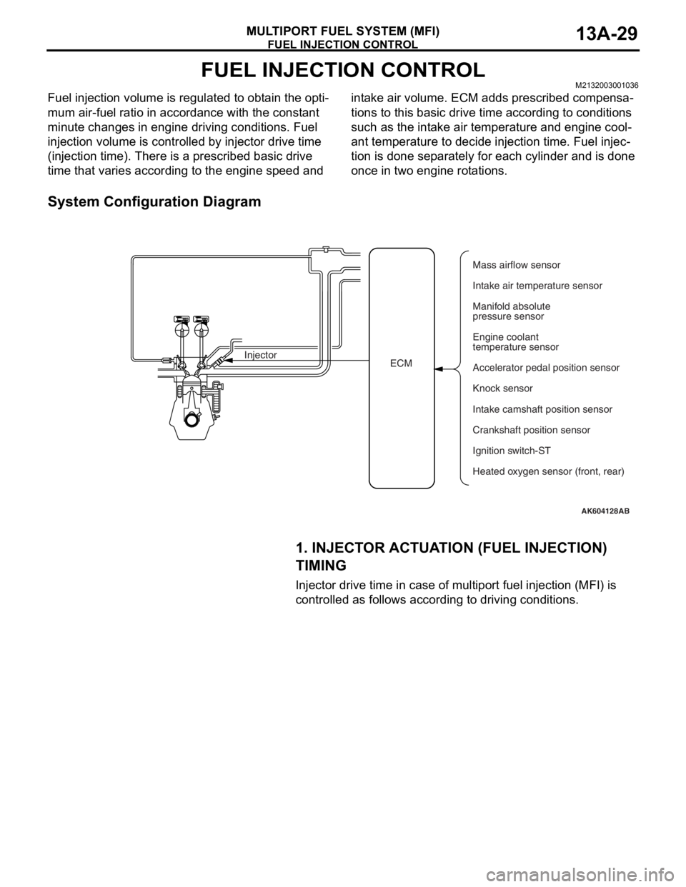
Fuel injection volume is regulated to obtain the opti-
mum air-fuel ratio in accordance with the constant
minute changes in engine driving conditions. Fuel
injection volume is controlled by injector drive time
(injection time). There is a prescribed basic drive
time that varies according to the engine speed and intake air volume. ECM adds prescribed compensa
-
tions to this basic drive time according to conditions
such as the intake air temperature and engine cool
-
ant temperature to decide injection time. Fuel injec-
tion is done separately for each cylinder and is done
once in two engine rotations.
System Configuration Diagram
1. INJECTOR ACTUATION (FUEL INJECTION)
TIMING
Injector drive time in case of multiport fuel injection (MFI) is
controlled as follows according to driving conditions.
AK604128AB
ECM InjectorMass airflow sensor
Intake air temperature sensor
Manifold absolute
pressure sensor
Engine coolant
temperature sensor
Accelerator pedal position sensor
Knock sensor
Intake camshaft position sensor
Ignition switch-ST
Heated oxygen sensor (front, rear) Crankshaft position sensor
Page 124 of 241
FUEL INJECTION CONTROL
MULTIPORT FUEL SYSTEM (MFI)13A-31
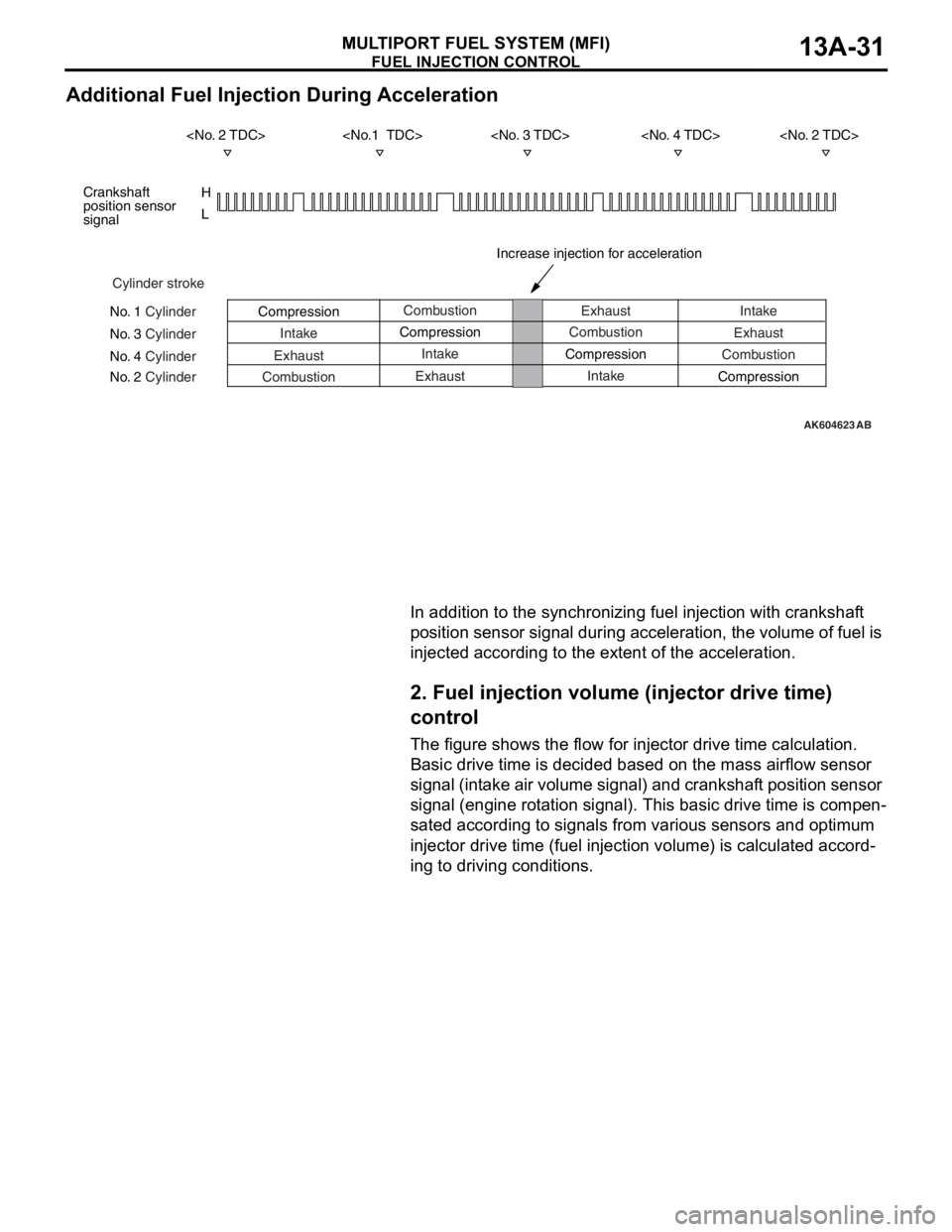
Additional Fuel Injection During Acceleration
In addition to the synchronizing fuel injection with crankshaft
position sensor signal during acceleration, the volume of fuel is
injected according to the extent of the acceleration.
2. Fuel injection volume (injector drive time)
control
The figure shows the flow for injector drive time calculation.
Basic drive time is decided based on the mass airflow sensor
signal (intake air volume signal) and crankshaft position sensor
signal (engine rotation signal). This basic drive time is compen
-
sated according to signals from various sensors and optimum
injector drive time (fuel injection volume) is calculated accord
-
ing to driving conditions.
AK604623
H
L
AB
Cylinder stroke
No. 1 Cylinder
No. 3 Cylinder
No. 4 Cylinder
No. 2 CylinderCombustion
Intake
Exhaust
CombustionExhaust
Compression
Intake
Exhaust CompressionCombustion
Intake CompressionIntake
Exhaust
Combustion
Compression Crankshaft
position sensor
signal
Increase injection for acceleration
Page 125 of 241
FUEL INJECTION CONTROL
MULTIPORT FUEL SYSTEM (MFI)13A-32
Fuel Injection Volume Control Block Diagram
.
AK602278AD
Mass airflow sensor
Crankshaft
position sensor
Heated oxygen
sensor
Engine coolant
temperature
compensation Engine coolant
temperature sensor
Manifold absolute
pressure sensorFuel pressure
compensation Barometric pressure
sensor
Battery voltage
compensation Battery voltageBasic fuel
injection time
determinationAir fuel ratio
compensation
(Predetermined
compensation)
Heated oxygen
sensor feedback
compensation
Injector Acceleration-
deceleration
compensation
Page 126 of 241
![MITSUBISHI LANCER EVOLUTION X 2008 Workshop Manual FUEL INJECTION CONTROL
MULTIPORT FUEL SYSTEM (MFI)13A-33
[Injector basic drive time]
Fuel injection is performed once per cycle for each cylinder.
Basic drive time refers to fuel injection volume (in MITSUBISHI LANCER EVOLUTION X 2008 Workshop Manual FUEL INJECTION CONTROL
MULTIPORT FUEL SYSTEM (MFI)13A-33
[Injector basic drive time]
Fuel injection is performed once per cycle for each cylinder.
Basic drive time refers to fuel injection volume (in](/manual-img/19/57326/w960_57326-125.png)
FUEL INJECTION CONTROL
MULTIPORT FUEL SYSTEM (MFI)13A-33
[Injector basic drive time]
Fuel injection is performed once per cycle for each cylinder.
Basic drive time refers to fuel injection volume (injector drive
time) to achieve theoretical air-fuel ratio for the intake air vol
-
ume of 1 cycle of 1 cylinder. Fuel injection volume changes
according to the pressure difference (injected fuel pressure)
between manifold absolute pressure and fuel pressure (con
-
stant). So, injected fuel pressure compensation is made to
injector drive time for theoretical air-fuel ratio to arrive at basic
drive time.
Intake air volume of each cycle of 1 cylinder is calculated by
ECM based on the mass airflow sensor signal and crankshaft
position sensor signal. Also, during engine start, the map value
prescribed by the engine coolant temperature sensor signal is
used as basic drive time.
.
AK602279AC
Basic fuel
injection timeFuel injection pressure compensation Intake air amount per cycle per cylinder
Theoretical air-fuel ratio