2008 MINI COOPER CONVERTIBLE ESP
[x] Cancel search: ESPPage 42 of 176
40
WIND DEFLECTOR
*
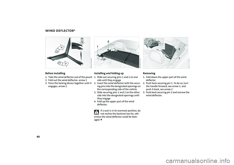
Before installing
1. Take the wind deflector out of the pouch
2. Fold out the wind deflector, arrow 1
3. Press the locking device together until it
engages, arrow 2.
Installing and folding up1. Slide out securing pins 1 and 2 on one
side until they engage
2. Insert the wind deflector with the secur-
ing pins into the designated openings on
the corresponding side of the vehicle
3. Slide securing pins 1 and 2 on the other
side into the designated openings until
they engage
4. Fold up the upper part of the wind
deflector.
If a seat is in its rearmost position, do
not recline the backrest too far, oth-
erwise the wind deflector could be dam-
aged.<
Removing1. Fold down the upper part of the wind
deflector
2. Push back securing pin 1. To do so, turn
the handle forward, see arrow 1, and
push it back, see arrow 2
3. Push back securing pin 2 and remove the
wind deflector.
Page 45 of 176
43
OVERVIEW REPAIRS OPERATIONCONTROLS DATA INDEX
SEAT ADJUSTMENTImportant adjustment information
Never try to adjust your seat while
operating the vehicle. The seat could
respond with an unexpected movement,
and the ensuing loss of vehicle control
could lead to an accident.
While driving, do not recline the backrest
too far toward the rear; this especially
applies to the front passenger seat. Other-
wise there is a risk that you will slide under
the safety belt in an accident, thus reducing
the protection provided by the safety
belt.<
Comply with the instructions on head
restraint height adjustment on page44
and on damaged safety belts on page47.
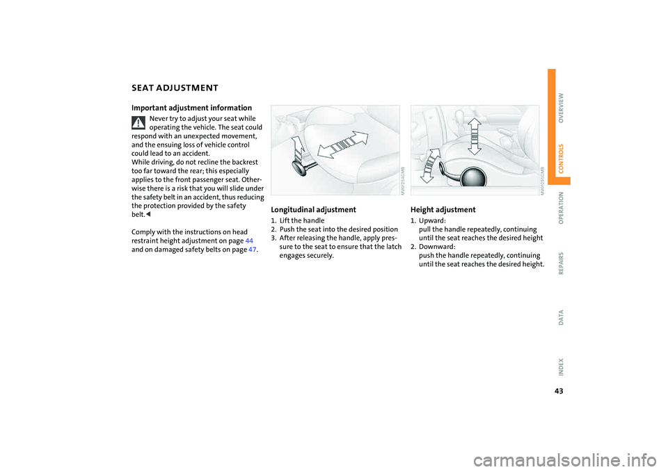
Longitudinal adjustment1. Lift the handle
2. Push the seat into the desired position
3. After releasing the handle, apply pres-
sure to the seat to ensure that the latch
engages securely.
Height adjustment 1. Upward:
pull the handle repeatedly, continuing
until the seat reaches the desired height
2. Downward:
push the handle repeatedly, continuing
until the seat reaches the desired height.
Page 54 of 176
52
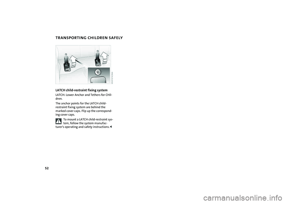
TRANSPORTING CHILDREN SAFELYLATCH child-restraint fixing systemLATCH: Lower Anchor and Tethers for CHil-
dren.
The anchor points for the LATCH child-
restraint fixing system are behind the
marked cover caps. Flip up the correspond-
ing cover caps.
To mount a LATCH child-restraint sys-
tem, follow the system manufac-
turer's operating and safety instructions.<
Page 62 of 176

60
PARKING LAMPS/LOW BEAMS1Parking lamps
2Low beams
3 Automatic headlamp control
*
Parking lamps
Turn the light switch to position 1.
The front, rear and side vehicle
lighting is switched on.
For the additional option of activating the
lights on one side of the vehicle for parking,
refer to Switching on the standing lamps,
page60.
The parking lamps discharge the bat-
tery.
Avoid using them for longer periods of
time; otherwise, you may not be able to
start the engine.<
Low beams
Turn the light switch to position 2.
With the low beams on and with
the ignition switched off, only the
parking lamps will remain on.
Automatic headlamp control*
In switch position 3, the system
automatically activates and can-
cels the low beams in response to
changes in ambient light, for example in
tunnels, at dusk, and when there is precipi-
tation.
When driving into a tunnel with bright
overhead lights, there may be a delay
before the low beams come on.
The low beams may also come on when the
sun is sitting low on a blue sky.
When you switch on the fog lamps,
the low-beam headlamps remain on
regardless of the ambient light. When the
daytime running lamps are activated, refer
to page61, the low beams come on and
remain lit when the switch is in position 1
and the ignition is switched on.<
Automatic headlamp control cannot
serve as a substitute for the driver's
judgement in determining when the vehi-
cle lights should be switched on. For exam-
ple, the sensors are not able to detect fog or
hazy weather. To avoid safety risks, you
should respond to these kinds of low-visi-
bility situations by switching the head-
lamps on manually.<
You can have the sensitivity of your
vehicle's automatic headlamp con-
trol adjusted.
lights, the low beams will stay lit for a pre-
set period of time.
You can have this function pro-
grammed.
In ignition key position 0:
Move the lever to the adequate turn signal
indicator position.
The standing lamps discharge the
battery. Avoid using them for longer
Page 74 of 176
72
DRIVING STABILITY CONTROL SYSTEMSYour MINI or MINI Convertible is equipped
with a series of systems that help maintain
driving stability even in adverse driving sit-
uations.Antilock Brake System (ABS)ABS keeps the wheels from locking during
braking. Steering stability is maintained
even during full brake applications. In this
way, active safety is enhanced.
ABS is operational each time the engine is
started. Braking safely, refer to page103.Cornering Brake Control CBCDriving stability and steering characteris-
tics are further enhanced while braking in
turns or during a lane change.Electronic Brake Force Distribution
(EBD)The system controls brake-force applica-
tion at the rear wheels in order to obtain
increased stability in the vehicle's braking
response.All Season traction Control (ASC)*ASC prevents slip at the drive wheels while
starting off and accelerating the vehicle.
ASC also recognizes unstable vehicle condi-tions, such as fishtailing or nose-diving. In
these cases, and subject to physical limits,
ASC helps to keep the vehicle on a steady
course by reducing engine speed and by
applying brakes at individual wheels. This
system optimizes driving stability and trac-
tion, especially when just starting off,
when accelerating or when cornering.
The ASC is operational each time you start
the engine. It integrates the Antilock Brake
System (ABS) and Electronic Brake Force
Distribution (EBD).
The laws of physics cannot be
repealed, even with ASC. An appropri-
ate driving style always remains the
responsibility of the driver. Avoid using the
additional safety margin provided by the
system as an excuse for taking unnecessary
risks.
Do not make any modifications to the ASC
system. Allow only authorized technicians
to perform service procedures on the
ASC.<
Dynamic Stability Control (DSC)*DSC prevents slip at the drive wheels while
starting off and accelerating the vehicle.
DSC also recognizes unstable vehicle condi-
tions, such as fishtailing or nose-diving. In
these cases, and subject to physical limits,
DSC helps to keep the vehicle on a steady
course by reducing engine speed and by
applying brakes at individual wheels.
The DSC is operational every time you start
the engine. It integrates All Season traction
Control (ASC).
The laws of physics cannot be
repealed, even with DSC. An appro-
priate driving style always remains the
responsibility of the driver. Avoid using the
additional safety margin provided by the
system as an excuse for taking unnecessary
risks.
Do not make any modifications to the DSC
system. Allow only authorized technicians
to perform service procedures on the
DSC.<
Page 80 of 176

78
TIRE PRESSURE MONITOR
*
>If TPM is temporarily malfunctioning due
to other systems or devices using the
same radio frequency.
Declaration according to NHTSA/
FMVSS 138 Tire Pressure Monitoring
SystemEach tire should be checked monthly when
cold and inflated to the inflation pressure
recommended by the vehicle manufacturer
on the vehicle placard or tire inflation pres-
sure label. If your vehicle has tires of a dif-
ferent size than the size indicated on the
vehicle placard or tire inflation pressure
label, you should determine the proper tire
inflation pressure for those tires. As an
added safety feature, your vehicle has been
equipped with a tire pressure monitoring
system, TPMS, that illuminates a low tire
pressure telltale when one or more of your
tires are significantly under-inflated.
Accordingly, when the low tire pressure
telltale illuminates, you should stop and
check your tires as soon as possible, and
inflate them to the proper pressure. Driving
on a significantly underinflated tire causes
the tire to overheat and can lead to tire fail-
ure. Underinflation also reduces fuel effi-
ciency and tire tread life, and may affect
the vehicle's handling and stopping ability.
Please note that the TPMS is not a substi-
tute for proper tire maintenance, and it is
the driver's responsibility to maintain cor-
rect tire pressure, even if underinflation has not reached the level at which the
TPMS low tire pressure telltale illuminates.
The TPMS malfunction indicator is com-
bined with the low tire pressure telltale.
When the system detects a malfunction,
the telltale will flash for approximately one
minute and then remain continuously lit.
This sequence will continue upon subse-
quent vehicle startups as long as the mal-
function exists. When the malfunction
indicator is illuminated, the system may
not be able to detect or signal low tire pres-
sure as intended. TPMS malfunctions may
occur for a variety of reasons, including the
installation of replacement or alternate
tires or wheels on the vehicle that prevent
the TPMS from functioning properly.
Always check the TPMS malfunction tell-
tale after replacing one or more tires or
wheels on your vehicle to ensure that the
replacement or alternate tires and wheels
allow the TPMS to continue to function
properly.
Page 81 of 176
79
OVERVIEW REPAIRS OPERATIONCONTROLS DATA INDEX
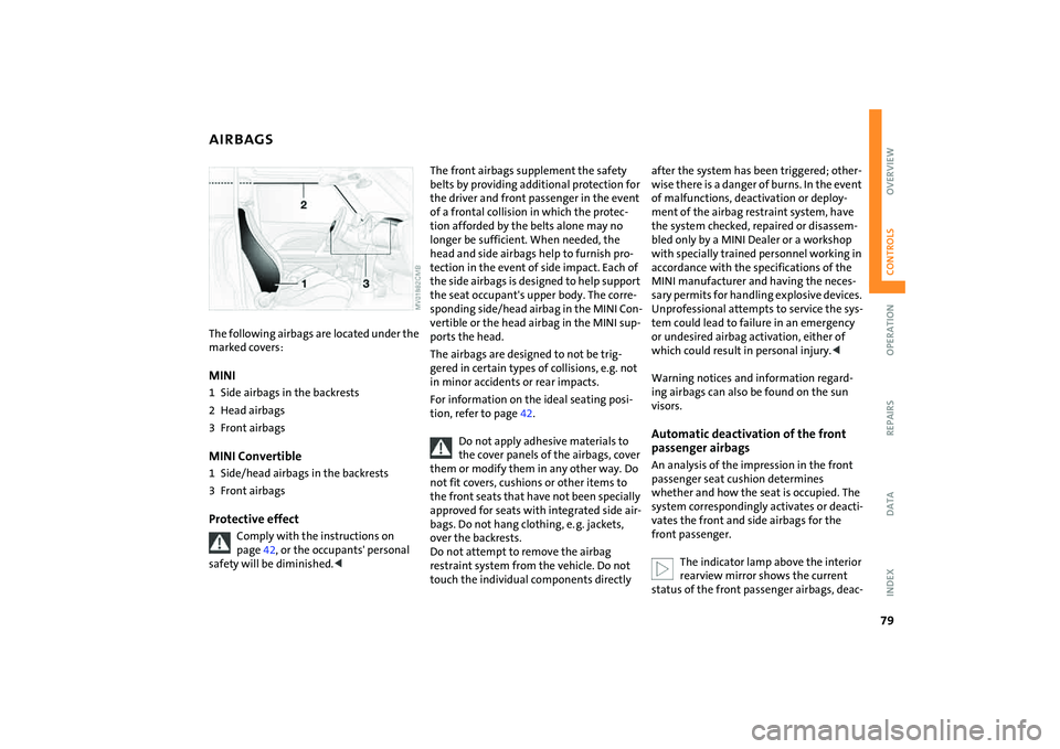
AIRBAGSThe following airbags are located under the
marked covers:MINI1 Side airbags in the backrests
2 Head airbags
3 Front airbags MINI Convertible1 Side/head airbags in the backrests
3 Front airbags Protective effect
Comply with the instructions on
page42, or the occupants' personal
safety will be diminished.<
The front airbags supplement the safety
belts by providing additional protection for
the driver and front passenger in the event
of a frontal collision in which the protec-
tion afforded by the belts alone may no
longer be sufficient. When needed, the
head and side airbags help to furnish pro-
tection in the event of side impact. Each of
the side airbags is designed to help support
the seat occupant's upper body. The corre-
sponding side/head airbag in the MINI Con-
vertible or the head airbag in the MINI sup-
ports the head.
The airbags are designed to not be trig-
gered in certain types of collisions, e.g. not
in minor accidents or rear impacts.
For information on the ideal seating posi-
tion, refer to page42.
Do not apply adhesive materials to
the cover panels of the airbags, cover
them or modify them in any other way. Do
not fit covers, cushions or other items to
the front seats that have not been specially
approved for seats with integrated side air-
bags. Do not hang clothing, e. g. jackets,
over the backrests.
Do not attempt to remove the airbag
restraint system from the vehicle. Do not
touch the individual components directly
after the system has been triggered; other-
wise there is a danger of burns. In the event
of malfunctions, deactivation or deploy-
ment of the airbag restraint system, have
the system checked, repaired or disassem-
bled only by a MINI Dealer or a workshop
with specially trained personnel working in
accordance with the specifications of the
MINI manufacturer and having the neces-
sary permits for handling explosive devices.
Unprofessional attempts to service the sys-
tem could lead to failure in an emergency
or undesired airbag activation, either of
which could result in personal injury.<
Warning notices and information regard-
ing airbags can also be found on the sun
visors.Automatic deactivation of the front
passenger airbagsAn analysis of the impression in the front
passenger seat cushion determines
whether and how the seat is occupied. The
system correspondingly activates or deacti-
vates the front and side airbags for the
front passenger.
The indicator lamp above the interior
rearview mirror shows the current
status of the front passenger airbags, deac-
Page 83 of 176

81
OVERVIEW REPAIRS OPERATIONCONTROLS DATA INDEX
PARK DISTANCE CONTROL (PDC)
*
The concept
The PDC assists you when you back into a
parking space. A signal tone tells you the
current distance to an object behind your
vehicle. To do this, four ultrasonic sensors
in the rear bumper measure the distance to
the nearest object.
The sensors on each side have a range of
approx. 2 ft/60 cm, the middle sensors one
of approx. 5 ft/1.5 m.
PDC is a parking aid that can identify
objects if they are approached slowly,
as is generally the case when parking.
Avoid driving towards objects rapidly; due
to underlying physical principles, the sys-
tem may otherwise alert you too late for
you to take evasive steps.
one second after you select reverse gear or
place the selector lever in position R.
Wait for this one second before you
drive backwards.<
The system is deactivated when you shift
away from Reverse.
You can have a signal tone set as a
confirmation that PDC has been acti-
vated.<
Acoustical signalsThe distance to an object is indicated by a
tone sounding at intervals. As the distance
between vehicle and object decreases, the
intervals between the tones become
shorter. A continuous tone indicates the
presence of an object less than 12 in/30 cm
away.
The warning signal is canceled after
approx. three seconds if the distance to the
object remains constant during this time,
for instance if you are moving parallel to a
wall.MalfunctionA continuous high-pitched tone will sound
during initial activation. The system is mal-
functioning. Have the system checked.Volume controlThe volume of the Park Distance Control
signal can be adjusted from level 1, soft, to
level 6, loud.
You can have this function set.<
System limitations
Even with PDC, final responsibility for
estimating the distance between the
vehicle and any objects always remains
with the driver.
Even when sensors are involved, there is a
blind spot in which objects cannot be
detected. Recognition of some objects can
be beyond the limits of physical ultrasonic
measurement, for example with towing
bars or hitches or with thin or wedge-
shaped objects. It is also possible that low
objects already detected, such as a curb
edge, can disappear in the blind spot of the
sensors before a continuous tone is
sounded, or that protruding objects higher
above the ground, such as ledges, are not
detected.
Loud sources of sound outside and inside
your vehicle can drown the PDC signal
tone.<
Keep the sensors clean and free of ice
or snow in order to ensure that they
will continue to operate effectively.
Do not apply high pressure spray to the
sensors for a prolonged period of time.
Always maintain a distance which is
greater than 4 in/10 cm.<