Page 405 of 474

�Turn housing cover1 counterclock-
wise and remove.
�Turn bulb socket5 with the bulb
counterclockwise and remove.
�Pull the")
404 Practical hints
Replacing bulbs
Low beam bulb (Halogen headlamps
only)
�Turn housing cover1 counterclock-
wise and remove.
�Turn bulb socket5 with the bulb
counterclockwise and remove.
�Pull the bulb out of bulb socket5.
�Press the new bulb into bulb socket5.
�Place bulb socket5 back into the
lamp and turn it clockwise.
�Reinstall housing cover1.
High beam/high beam flasher bulb
(Halogen headlamps) / High beam
flasher bulb (Bi-Xenon* headlamps)
�Turn bulb socket3 with the bulb
counterclockwise and remove.
�Pull the bulb out of bulb socket3.
�Press the new bulb into bulb socket3.
�Place bulb socket3 back into the
lamp and turn it clockwise.Front turn signal bulb
�Turn bulb socket2 with the bulb
counterclockwise and remove.
�Press gently onto the bulb and turn it
counterclockwise out of bulb
socket2.
�Press the new bulb gently into bulb
socket2 and turn it clockwise.
�Place bulb socket2 back into the
lamp and turn it clockwise.
Parking and standing lamp bulb
�Turn bulb socket4 with the bulb
counterclockwise and remove.
�Pull the bulb out of bulb socket4.
�Press the new bulb into bulb socket4.
�Place bulb socket4 back into the
lamp and turn it clockwise.
Replacing bulbs for rear lamps
Before you start to replace a bulb for a rear
lamp, do the following first:
�Turn the exterior lamp switch to
positionM (
�page 109).
�Open the trunk lid (�page 99).
Tail lamp unit
1Bulb socket for rear fog lamp
(driver’s side only)
2Bulb socket for turn signal lamp
3Bulb socket for backup lamp
Page 406 of 474
405 Practical hints
Replacing bulbs
�Fold corresponding trim to side.
�Turn the respective bulb socket coun-
terclockwise and remove.
�Press gently onto the bulb and turn
counterclockwise out of its bulb sock-
et.
�Press the new bulb gently into its bulb
socket and turn clockwise.
�Reinstall the bulb socket and turn
clockwise until it engages.
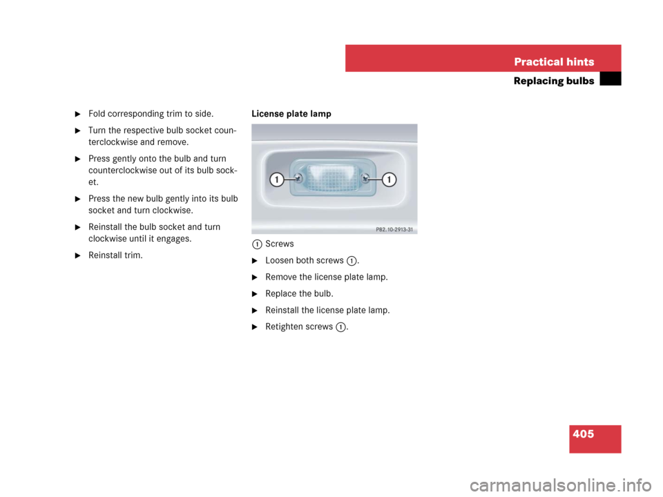
�Reinstall trim.License plate lamp
1Screws�Loosen both screws1.
�Remove the license plate lamp.
�Replace the bulb.
�Reinstall the license plate lamp.
�Retighten screws1.
Page 415 of 474
.
�Take the spare wheel, wheel wrench,
wheel bolts, jack, and electric air")
414 Practical hints
Flat tire
Mounting the spare wheel
Preparing the vehicle
�Prepare the vehicle as described
(
�page 408).
�Take the spare wheel, wheel wrench,
wheel bolts, jack, and electric air pump
out of the trunk (
�page 389).Lifting the vehicle
�Prevent the vehicle from rolling away
by blocking wheels with wheel chocks
or other sizeable objects.
One wheel chock is included with the
vehicle tool kit (
�page 390).
When changing wheel on a level surface:
�Place one wheel chock or other size-
able object in front of and another
wheel chock or other sizeable object
behind the wheel that is diagonally
opposite to the wheel being changed.
Always try lifting the vehicle using the jack
on a level surface. However, should cir-
cumstances require you to do so on a hill,
place the wheel chock or other sizeable
object and the other wheel chock or other
sizeable object as follows:
�Place wheel chocks and other sizeable
objects on the downhill side blocking
both wheels of the axle not being
worked on.
Warning!G
The dimensions of the spare wheel are dif-
ferent from those of the road wheels. As a
result, the vehicle handling characteristics
change when driving with a spare wheel with
collapsible tire mounted. Adapt your driving
style accordingly.
The spare wheel is for temporary use only.
When driving with spare wheel mounted,
ensure proper tire inflation pressure
and do not exceed vehicle speed of
50 mph (80 km/h).
Drive to the nearest Mercedes-Benz Center
as soon as possible to have the spare wheel
replaced with a regular road wheel.
Never operate the vehicle with more than
one spare wheel mounted.
Do not switch off the ESP
® when a spare
wheel is mounted.
Page 416 of 474
.
The jack t")
415 Practical hints
Flat tire
1Wheel wrench
�On wheel to be changed, loosen but do
not yet remove the wheel bolts in direc-
tion of arrow (approximately one full
turn with wheel wrench1).
The jack take-up brackets are located di-
rectly behind the front wheel housings and
in front of the rear wheel housings.2Jack
3Take-up bracket�Place jack2 on firm ground.
�Position jack2 under take-up
bracket3 so that it is always vertical
(plumb-line) as seen from the side,
even if the vehicle is parked on an
incline.
Warning!G
The jack is designed exclusively for jacking
up the vehicle at the jack take-up brackets
built into either side of the vehicle. To help
avoid personal injury, use the jack only to lift
the vehicle during a wheel change. Never
get beneath the vehicle while it is supported
by the jack. Keep hands and feet away from
the area under the lifted vehicle. Always
firmly set parking brake and block wheels
before raising vehicle with jack.
Do not disengage parking brake while the
vehicle is raised. Be certain that the jack is
always vertical (plumb line) when in use, es-
pecially on hills. Always try to use the jack
on level surface. Be sure the jack arm is fully
seated in the jack take-up bracket. Always
lower the vehicle onto sufficient capacity
jackstands before working under the
vehicle.
Warning!G
Position the jack only on the jack take-up
brackets designed for this purpose.
If the jack is not properly positioned, the
vehicle may fall off of the jack.
��
Page 421 of 474

420 Practical hints
Flat tire
Lowering the vehicle
�Lower vehicle by turning the crank
counterclockwise until vehicle is
resting fully on its own weight.
�Remove the jack.
1-5 Wheel bolts
�Tighten the five wheel bolts evenly in
the direction of the arrow, following the
diagonal sequence illustrated
(1to5), until all bolts are tight.
Observe a tightening torque of
80 lb-ft (110 Nm).
�Fully collapse the jack.
�Place the vehicle tool kit, electric air
pump, and the jack back in the storage
compartment underneath the trunk
floor.
�Wrap the damaged wheel in the protec-
tive sheet provided with the vehicle
tool kit and put the wheel in the trunk.
For information on storing the spare wheel
in the trunk after it has been replaced by a
regular road wheel, see “Storing the spare
wheel with collapsible tire” (
�page 392).
Warning!G
Inflate the collapsible tire using the electric
pump (
�page 418) before lowering the
vehicle.
Warning!G
Have the tightening torque checked after
changing a wheel. The wheels could come
loose if they are not tightened to a torque of
80 lb-ft (110 Nm).
iThe flat tire may be transported in the trunk
when the retractable hardtop is closed.
Page 424 of 474
.
�Make sure the gear selector lever* is
set to positionP (manual transmission
to Neutral).")
423 Practical hints
Battery
Disconnecting the battery
1Water tray
2Lock
�Apply the parking brake (�page 59).
�Make sure the gear selector lever* is
set to positionP (manual transmission
to Neutral).
�Turn off all electrical consumers.
�Remove the SmartKey from the starter
switch.
�Open the hood (�page 294).
�Turn locks2 one quarter turn.
�Remove water tray1.
�Read and observe safety instructions
and precautions (
�page 302) and
(
�page 422).
�Use a 10 mm open-end wrench to dis-
connect the negative lead from battery
negative terminal3 (
�page 422).
�Remove the cover from battery positive
terminal 2 (
�page 422).
�Use a 10 mm open-end wrench to dis-
connect the positive lead from battery
positive terminal2 (
�page 422).
Warning!G
With a disconnected battery
�you will no longer be able to turn the
SmartKey in the starter switch
�automatic transmission*: the gear se-
lector lever will remain locked in
positionP
!Always disconnect the battery in the order
described below. Otherwise the vehicle’s
electronics can be damaged.
Page 426 of 474
425 Practical hints
Battery
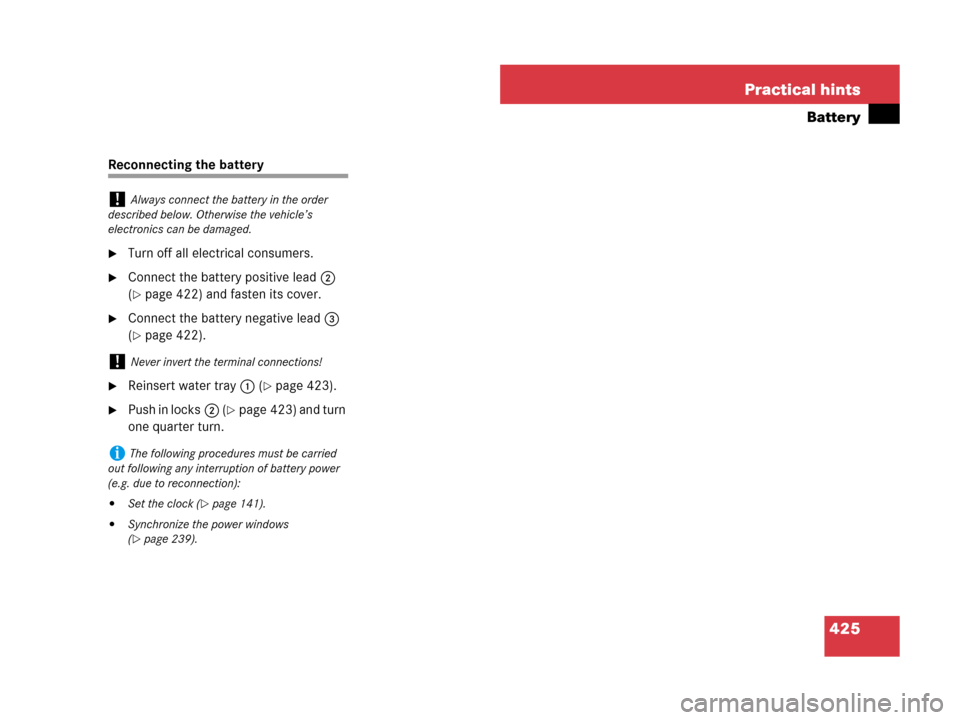
Reconnecting the battery
�Turn off all electrical consumers.
�Connect the battery positive lead2
(
�page 422) and fasten its cover.
�Connect the battery negative lead3
(
�page 422).
�Reinsert water tray 1 (�page 423).
�Push in locks2 (�page 423) and turn
one quarter turn.
!Always connect the battery in the order
described below. Otherwise the vehicle’s
electronics can be damaged.
!Never invert the terminal connections!
iThe following procedures must be carried
out following any interruption of battery power
(e.g. due to reconnection):
�Set the clock (�page 141).
�Synchronize the power windows
(
�page 239).
Page 429 of 474

428 Practical hints
Towing the vehicle
Mercedes-Benz recommends that the vehi-
cle be transported with all wheels off the
ground using flatbed or appropriate wheel
lift/dolly equipment.
When circumstances do not permit the
recommended towing methods, the vehi-
cle may be towed with all wheels on the
ground or front wheels raised only so far as
necessary to have the vehicle moved to a
safe location where the recommended
towing methods can be employed.
!Vehicles with automatic transmission*: Do
not tow-start vehicle.
!Use flatbed or wheel lift/dolly equipment
with the SmartKey in the starter switch in
position0.
Do not tow with sling-type equipment. Towing
with sling-type equipment over bumpy roads will
damage radiator and supports.
To prevent damage during transport, do not tie
down vehicle by its chassis or suspension parts.
Use the towing eyes.
Switch off the tow-away alarm (
�page 91) and
the automatic central locking (
�page 102).
Warning!G
If circumstances require towing the vehicle
with all wheels on the ground, always tow
with a tow bar if:
�the engine will not run
�there is a malfunction in the brake
system
�there is a malfunction in the power
supply or in the vehicle’s electrical
system
This is necessary to adequately control the
towed vehicle.
Prior to towing the vehicle with all wheels on
the ground, make sure the SmartKey is in
starter switch position2.
If the SmartKey is left in starter switch
position0 for an extended period of time, it
can no longer be turned in the switch. In this
case, the steering is locked. To unlock,
remove SmartKey from starter switch and
reinsert.
Warning!G
With the engine not running, there is no
power assistance for the brake and steering
systems. In this case, it is important to keep
in mind that a considerably higher degree of
effort is necessary to brake and steer the
vehicle. Adapt your driving accordingly.
!If the vehicle is towed with the front axle
raised, the gear selector lever* must be in
positionN (manual transmission: gear shift lever
in neutral position) and the engine must be shut
off (SmartKey in starter switch position0or1).
Active braking action through the ESP
® may
otherwise seriously damage the brake system.
When towing the vehicle with all wheels on the
ground, the gear selector lever* must be in
positionN (manual transmission: gear shift lever
in neutral position) and the SmartKey must be in
starter switch position2.
When towing the vehicle with all wheels on the
ground or the front axle raised, the vehicle
may be towed only for distances up to
30 miles (50 km) and at a speed not to
exceed 30 mph (50 km/h).