Page 673 of 761

672 Practical hints
Unlocking/locking in an emergency
Unlocking the trunk
A minimum height clearance of 6.0 ft
(1.8 m) is required to open the trunk lid.
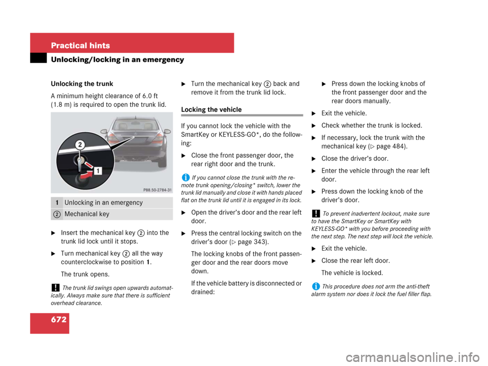
�Insert the mechanical key2 into the
trunk lid lock until it stops.
�Turn mechanical key2 all the way
counterclockwise to position 1.
The trunk opens.
�Turn the mechanical key2 back and
remove it from the trunk lid lock.
Locking the vehicle
If you cannot lock the vehicle with the
SmartKey or KEYLESS-GO*, do the follow-
ing:
�Close the front passenger door, the
rear right door and the trunk.
�Open the driver’s door and the rear left
door.
�Press the central locking switch on the
driver’s door (
�page 343).
The locking knobs of the front passen-
ger door and the rear doors move
down.
If the vehicle battery is disconnected or
drained:
�Press down the locking knobs of
the front passenger door and the
rear doors manually.
�Exit the vehicle.
�Check whether the trunk is locked.
�If necessary, lock the trunk with the
mechanical key (
�page 484).
�Close the driver’s door.
�Enter the vehicle through the rear left
door.
�Press down the locking knob of the
driver’s door.
�Exit the vehicle.
�Close the rear left door.
The vehicle is locked.
1Unlocking in an emergency
2Mechanical key
!The trunk lid swings open upwards automat-
ically. Always make sure that there is sufficient
overhead clearance.
iIf you cannot close the trunk with the re-
mote trunk opening/closing* switch, lower the
trunk lid manually and close it with hands placed
flat on the trunk lid until it is engaged in its lock.
!To prevent inadvertent lockout, make sure
to have the SmartKey or SmartKey with
KEYLESS-GO* with you before proceeding with
the next step. The next step will lock the vehicle.
iThis procedure does not arm the anti-theft
alarm system nor does it lock the fuel filler flap.
Page 674 of 761

673 Practical hints
Unlocking/locking in an emergency
Mechanically releasing the electronic
parking brake
Depending on vehicle production date your
vehicle may be equipped with a mechani-
cal release device for releasing the elec-
tronic parking brake. It is located behind
the fuel filler flap next to the fuel cap.
1Protective cap
2Release tool
3Pulling
�Shift the automatic transmission to P
(
�page 399).
�Prevent the vehicle from rolling away
by blocking a rear wheel with the wheel
chock. A wheel chock is included with
the vehicle tool kit (
�page 668).
�Open fuel filler flap.
�Remove protective cap1.
�Screw release tool2 from vehicle tool
kit clockwise 2 to 3 rotations onto re-
lease cable.
�Pull release tool2 in direction of
arrow3.
The electronic parking brake is re-
leased. The red indicator lamp0
(USA only) or! (Canada only) flash-
es. The message “Parking brake See
Oper. Manual” appears on the multi-
function display.
�Unscrew release tool2 from release
cable.
�Reattach protective cap1.
�Store release tool2 in vehicle tool kit.
After it has been unlocked, you can engage
the electronic parking brake again from
the driver’s seat.
�Press the electronic parking brake han-
dle (
�page 395).
iIf your vehicle is not equipped a mechanical
release device for releasing the electronic park-
ing brake contact Roadside Assistance or an au-
thorized Mercedes-Benz Center.
Warning!G
If you mechanically release the electronic
parking brake, the vehicle may start to move
on its own. Make sure that no one is in front
of or behind the vehicle. Otherwise, an acci-
dent could occur resulting in injury or fatali-
ty. Before releasing the electronic parking
brake, shift the automatic transmission to P
(
�page 399) and secure your vehicle in
place using the chock from the vehicle tool
kit.
iIf the electronic parking brake is not re-
leased, pull the release tool again with more
force.
Page 675 of 761

674 Practical hints
Opening/closing in an emergency
Power tilt/sliding sunroof or panorama
roof with power tilt/sliding panel*
Depending on vehicle production date your
vehicle may be equipped with a crank to
open or close the tilt/sliding sunroof or
tilt/sliding panel manually should an elec-
trical malfunction occur.The drive mechanism is behind the left sun
visor.
1Cover
�Remove cover1.
2Crank
�Take crank2 from the Operator’s
Manual pouch.
�Switch on the ignition.
�Insert crank2 through the hole.
�Turn crank2 clockwise to:
�slide roof panel/sunroof closed
�raise roof panel/sunroof at the rear
�Turn crank2 counterclockwise to:
�slide roof panel/sunroof open
�lower roof panel/sunroof at the
rear
iIf your vehicle is not equipped with a crank
and you cannot open or close the tilt/sliding
sunroof or tilt/sliding panel due to a malfunction
contact Roadside Assistance or an authorized
Mercedes-Benz Center.
iTurn crank2 slowly and smoothly.
The tilt/sliding sunroof (
�page 488) or tilt/slid-
ing panel (
�page 492) must be synchronized af-
ter being operated manually.
Page 682 of 761

681 Practical hints
Replacing bulbs
1Cover 1
2Cover 2
3Cover 3
Removing and installing washer fluid
reservoir on left-hand side
Vehicles with Airmatic*
You must remove the washer fluid reser-
voir in order to change the bulbs of the
front headlamp on the left-hand side. The
washer fluid reservoir is on the front
left-hand side of the engine compartment.Washer fluid reservoir (example illustration
from S 550)
1Retaining screw
Removing
�Turn retaining screw1 counterclock-
wise.
�Take washer fluid reservoir out of
mounting.
�Place washer fluid reservoir to the side
and do not disconnect any wires or ca-
bles.Installing
�Guide washer fluid reservoir into
mounting so that the bottom retaining
lug slides into the rubber sleeve on the
longitudinal member.
�Turn retaining screw1 clockwise.
Bi-Xenon headlamps
Warning!G
Do not remove the cover for the Bi-Xenon
headlamp. Because of high voltage in Xenon
lamps, it is dangerous to replace the bulb or
repair the lamp and its components. We rec-
o mm e nd that y ou ha ve s uc h wo rk do ne b y a
qualified technician.
Page 683 of 761

682 Practical hints
Replacing bulbs
High beam flasher lamp
In vehicles with Bi-Xenon headlamps, you
can only change the halogen bulb for the
high-beam flasher lamp.
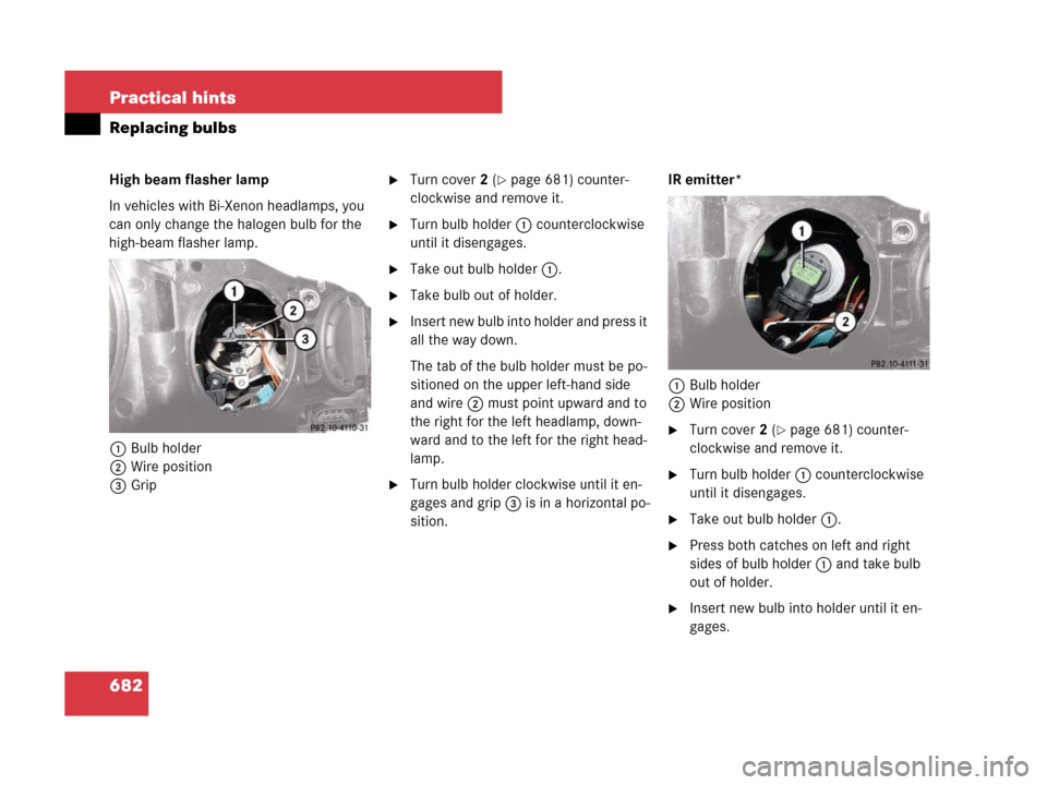
1Bulb holder
2Wire position
3Grip�Turn cover2 (�page 681) counter-
clockwise and remove it.
�Turn bulb holder1 counterclockwise
until it disengages.
�Take out bulb holder1.
�Take bulb out of holder.
�Insert new bulb into holder and press it
all the way down.
The tab of the bulb holder must be po-
sitioned on the upper left-hand side
and wire2 must point upward and to
the right for the left headlamp, down-
ward and to the left for the right head-
lamp.
�Turn bulb holder clockwise until it en-
gages and grip3 is in a horizontal po-
sition.IR emitter*
1Bulb holder
2Wire position
�Turn cover2 (�page 681) counter-
clockwise and remove it.
�Turn bulb holder1 counterclockwise
until it disengages.
�Take out bulb holder1.
�Press both catches on left and right
sides of bulb holder1 and take bulb
out of holder.
�Insert new bulb into holder until it en-
gages.
Page 684 of 761

683 Practical hints
Replacing bulbs
�Insert bulb holder1 into guide in
headlamp. Wire2 must point down-
ward and to the right.
�Turn bulb holder1 clockwise until it
engages and wire2 points downward
and to the left.
Corner-illuminating lamp
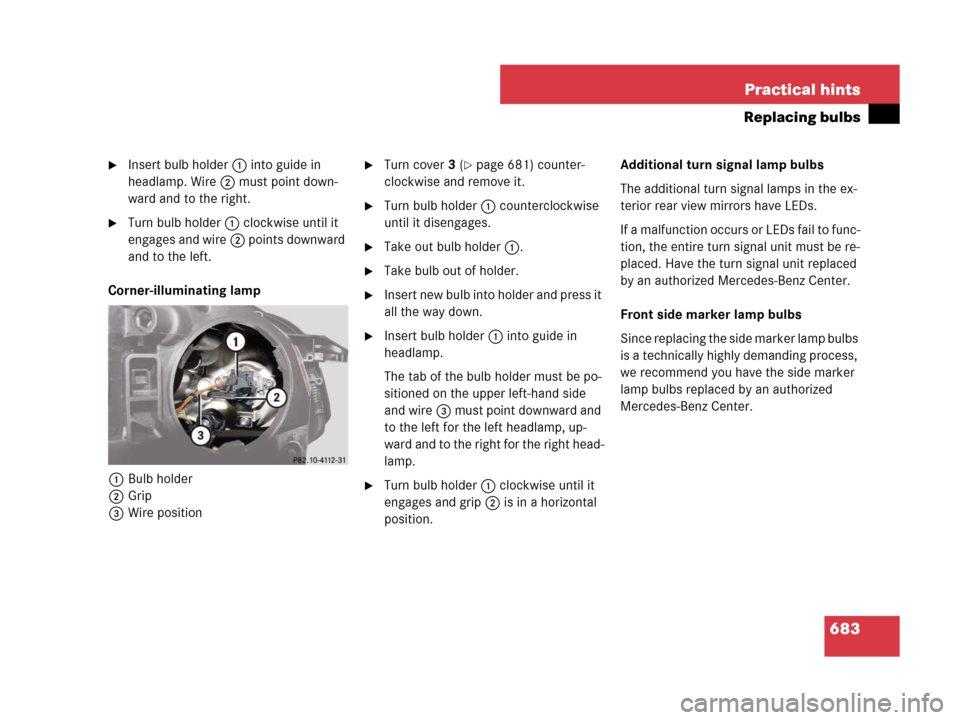
1Bulb holder
2Grip
3Wire position
�Turn cover3 (�page 681) counter-
clockwise and remove it.
�Turn bulb holder1 counterclockwise
until it disengages.
�Take out bulb holder1.
�Take bulb out of holder.
�Insert new bulb into holder and press it
all the way down.
�Insert bulb holder1 into guide in
headlamp.
The tab of the bulb holder must be po-
sitioned on the upper left-hand side
and wire3 must point downward and
to the left for the left headlamp, up-
ward and to the right for the right head-
lamp.
�Turn bulb holder1 clockwise until it
engages and grip2 is in a horizontal
position.Additional turn signal lamp bulbs
The additional turn signal lamps in the ex-
terior rear view mirrors have LEDs.
If a malfunction occurs or LEDs fail to func-
tion, the entire turn signal unit must be re-
placed. Have the turn signal unit replaced
by an authorized Mercedes-Benz Center.
Front side marker lamp bulbs
Since replacing the side marker lamp bulbs
is a technically highly demanding process,
we recommend you have the side marker
lamp bulbs replaced by an authorized
Mercedes-Benz Center.
Page 689 of 761

688 Practical hints
Flat tire
The jack take-up brackets are located di-
rectly behind the front wheel housings and
in front of the rear wheel housings.
2Jack take-up bracket
3Jack
4Crank
�Place jack2 on firm ground.
�Position jack3 under take-up
bracket2 so that it is always vertical
(plumb-line) as seen from the side,
even if the vehicle is parked on an
incline.
�Turn crank4 clockwise until jack3
is fully seated in take-up bracket2
and the jack base evenly meets the
ground.
�Jack up the vehicle until the wheel is a
maximum of 1.2 in (3 cm) from the
ground. Never start engine while
vehicle is raised.
Warning!G
Position the jack only on the jack take-up
brackets designed for this purpose.
If the jack is not properly positioned, the ve-
hicle may fall off the jack and cause serious
personal injury or damage to the vehicle.
Warning!G
The jack is intended only for lifting the
vehicle briefly for wheel changes. It is not
suited for performing maintenance work
under the vehicle.
�Never start the engine when the vehicle
is raised.
�Never lie down under the raised vehicle.
��
Page 691 of 761

690 Practical hints
Flat tire
�Clean contact surfaces of wheel and
wheel hub.
�Guide the spare wheel onto the align-
ment bolt and push it on.
�Insert wheel bolts and tighten them
slightly.
�Unscrew the alignment bolt, install the
last wheel bolt and tighten slightly.Lowering the vehicle
�Lower vehicle by turning crank coun-
terclockwise until vehicle is resting ful-
ly on its own weight.
�Remove the jack.
1 - 5 Wheel bolts
!Wheel bolts2 must be used when mount-
ing a Minispare wheel with steel rim. The use of
any wheel bolts other than wheel bolts2 for a
Minispare wheel with steel rim will physically
damage the vehicle’s brakes.
Wheel bolts1 must be used when mounting a
Minispare wheel with light alloy rim. The use of
any wheel bolts other than wheel bolts1 for
a Minispare wheel with light alloy rim will physi-
cally damage the vehicle’s brakes.
Warning!G
Make sure to use the original length wheel
bolts when remounting the original wheel
after it has been repaired.!To avoid paint damage, place wheel flat
against hub and hold it there while installing first
wheel bolt.