Page 710 of 801
 is required to open the trunk lid.�
Insert the mechanical key2 into the
trunk l")
709 Practical hints
Unlocking/locking in an emergency
Unlocking the trunk
A minimum height clearance of 6.0 ft
(1.8 m) is required to open the trunk lid.�
Insert the mechanical key2 into the
trunk lid lock until it stops.
�
Turn mechanical key2 all the way
counterclockwise to position 1.
The trunk opens.
�
Turn the mechanical key2 back and
remove it from the trunk lid lock.
Locking the vehicle
If you cannot lock the vehicle with the
SmartKey or KEYLESS-GO*, do the follow-
ing:�
Close the front passenger door, the
rear right door and the trunk.
�
Open the driver’s door and the rear left
door.
�
Press the central locking switch on the
driver’s door (
�page 369).
The locking knobs of the front passen-
ger door and the rear doors move
down.
If the vehicle battery is disconnected or
drained:
�
Press down the locking knobs of
the front passenger door and the
rear doors manually.
�
Exit the vehicle.
�
Check whether the trunk is locked.
�
If necessary, lock the trunk with the
mechanical key (
�page 517).
�
Close the driver’s door.
�
Enter the vehicle through the rear left
door.
�
Press down the locking knob of the
driver’s door.
�
Exit the vehicle.
�
Close the rear left door.
The vehicle is locked.
1
Unlocking in an emergency
2
Mechanical key
!
The trunk lid swings open upwards automat-
ically. Always make sure that there is sufficient
overhead clearance.
i
If you cannot close the trunk with the re-
mote trunk opening/closing* switch, lower the
trunk lid manually and close it with hands placed
flat on the trunk lid until it is engaged in its lock.
!
To prevent inadvertent lockout, make sure
to have the SmartKey or SmartKey with
KEYLESS-GO* with you before proceeding with
the next step. The next step will lock the vehicle.
i
This procedure does not arm the anti-theft
alarm system nor does it lock the fuel filler flap.
Page 718 of 801
717 Practical hints
Replacing bulbs
Replacing bulbs for front lamps
Before you start to replace a bulb for a
front lamp, do the following first:�
Turn the exterior lamp switch to M
(�page 399).
�
Open the hood (
�page 573).
1Cover 1
2Cover 2
3Cover 3Removing and installing washer fluid
reservoir on left-hand side
Vehicles with Airmatic*
You must remove the washer fluid reser-
voir in order to change the bulbs of the
front headlamp on the left-hand side. The
washer fluid reservoir is on the front
left-hand side of the engine compartment.
Washer fluid reservoir (example illustration
from S 550)1Retaining screwRemoving
�
Turn retaining screw1 counterclock-
wise.
�
Take washer fluid reservoir out of
mounting.
�
Place washer fluid reservoir to the side
and do not disconnect any wires or ca-
bles.
Installing
�
Guide washer fluid reservoir into
mounting so that the bottom retaining
lug slides into the rubber sleeve on the
longitudinal member.
�
Turn retaining screw1 clockwise.
Page 719 of 801
718 Practical hintsReplacing bulbsBi-Xenon headlamps High beam flasher lamp
In vehicles with Bi-Xenon headlamps, you
can only change the halogen bulb for the
high-beam flasher lamp.
1Bulb holder
2Wire position
3Grip
�
Turn cover2 (
�page 717) counter-
clockwise and remove it.
�
Turn bulb holder1 counterclockwise
until it disengages.
�
Take out bulb holder1.
�
Take bulb out of holder.
�
Insert new bulb into holder and press it
all the way down.
The tab of the bulb holder must be po-
sitioned on the upper left-hand side
and wire2 must point upward and to
the right for the left headlamp, down-
ward and to the left for the right head-
lamp.
�
Turn bulb holder clockwise until it en-
gages and grip3 is in a horizontal po-
sition.
Warning!
G
Do not remove the cover for the Bi-Xenon
headlamp. Because of high voltage in Xenon
lamps, it is dangerous to replace the bulb or
repair the lamp and its components. We rec-
ommend that you have such work done by a
qualified technician.
Page 720 of 801
 counter-
clockwise and remove it.
�
Turn bulb holder1 counterclockwise
until it disengages.
�
Tak")
719 Practical hints
Replacing bulbs
IR emitter*
1Bulb holder
2Wire position�
Turn cover2 (
�page 717) counter-
clockwise and remove it.
�
Turn bulb holder1 counterclockwise
until it disengages.
�
Take out bulb holder1.
�
Press both catches on left and right
sides of bulb holder1 and take bulb
out of holder.
�
Insert new bulb into holder until it en-
gages.
�
Insert bulb holder1 into guide in
headlamp. Wire2 must point down-
ward and to the right.
�
Turn bulb holder1 clockwise until it
engages and wire2 points downward
and to the left.
Corner-illuminating lamp
1Bulb holder
2Grip
3Wire position
�
Turn cover3 (
�page 717) counter-
clockwise and remove it.
�
Turn bulb holder1 counterclockwise
until it disengages.
�
Take out bulb holder1.
�
Take bulb out of holder.
�
Insert new bulb into holder and press it
all the way down.
�
Insert bulb holder1 into guide in
headlamp.
The tab of the bulb holder must be po-
sitioned on the upper left-hand side
and wire3 must point downward and
to the left for the left headlamp, up-
ward and to the right for the right head-
lamp.
�
Turn bulb holder1 clockwise until it
engages and grip2 is in a horizontal
position.
Page 726 of 801

725 Practical hints
Flat tire
The jack take-up brackets are located di-
rectly behind the front wheel housings and
in front of the rear wheel housings.
2Jack take-up bracket
3Jack
4Crank�
Place jack2 on firm ground.
�
Position jack3 under take-up
bracket2 so that it is always vertical
(plumb-line) as seen from the side,
even if the vehicle is parked on an
incline.
�
Turn crank4 clockwise until jack3
is fully seated in take-up bracket2
and the jack base evenly meets the
ground.
�
Jack up the vehicle until the wheel is a
maximum of 1.2 in (3 cm) from the
ground. Never start engine while
vehicle is raised.
Warning!
G
Position the jack only on the jack take-up
brackets designed for this purpose.
If the jack is not properly positioned, the ve-
hicle may fall off the jack and cause serious
personal injury or damage to the vehicle.Warning!
G
The jack is intended only for lifting the
vehicle briefly for wheel changes. It is not
suited for performing maintenance work
under the vehicle.�
Never start the engine when the vehicle
is raised.
�
Never lie down under the raised vehicle.
Page 728 of 801

727 Practical hints
Flat tire
�
Clean contact surfaces of wheel and
wheel hub.
�
Guide the spare wheel onto the align-
ment bolt and push it on.
�
Insert wheel bolts and tighten them
slightly.
�
Unscrew the alignment bolt, install the
last wheel bolt and tighten slightly.Lowering the vehicle
�
Lower vehicle by turning crank coun-
terclockwise until vehicle is resting ful-
ly on its own weight.
�
Remove the jack.
1 - 5 Wheel bolts
!
Wheel bolts2 must be used when mount-
ing a Minispare wheel with steel rim. The use of
any wheel bolts other than wheel bolts2 for a
Minispare wheel with steel rim will physically
damage the vehicle’s brakes.
Wheel bolts1 must be used when mounting a
Minispare wheel with light alloy rim. The use of
any wheel bolts other than wheel bolts1 for
a Minispare wheel with light alloy rim will physi-
cally damage the vehicle’s brakes.
Warning!
G
Make sure to use the original length wheel
bolts when remounting the original wheel
after it has been repaired.
!
To avoid paint damage, place wheel flat
against hub and hold it there while installing first
wheel bolt.
Page 741 of 801
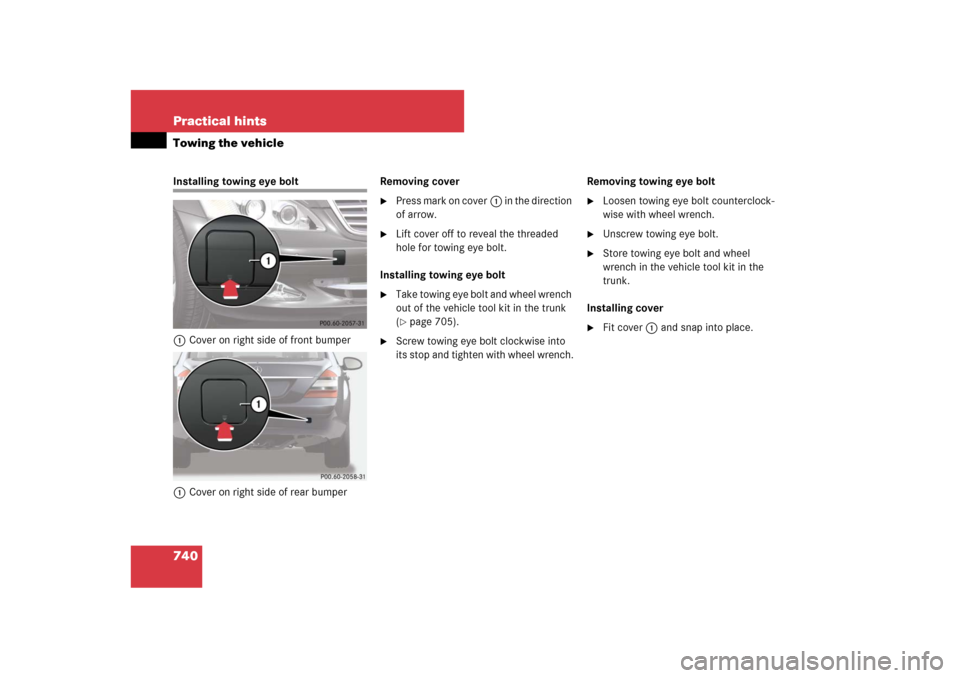
740 Practical hintsTowing the vehicleInstalling towing eye bolt
1Cover on right side of front bumper
1Cover on right side of rear bumperRemoving cover
�
Press mark on cover1 in the direction
of arrow.
�
Lift cover off to reveal the threaded
hole for towing eye bolt.
Installing towing eye bolt
�
Take towing eye bolt and wheel wrench
out of the vehicle tool kit in the trunk
(�page 705).
�
Screw towing eye bolt clockwise into
its stop and tighten with wheel wrench.Removing towing eye bolt
�
Loosen towing eye bolt counterclock-
wise with wheel wrench.
�
Unscrew towing eye bolt.
�
Store towing eye bolt and wheel
wrench in the vehicle tool kit in the
trunk.
Installing cover
�
Fit cover1 and snap into place.
Page:
< prev 1-8 9-16 17-24