2008 MERCEDES-BENZ R-CLASS MPV ECU
[x] Cancel search: ECUPage 204 of 373

Loading and stowing
201
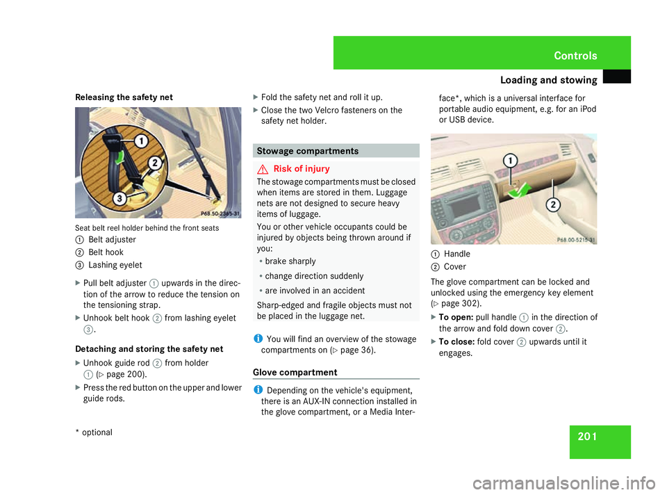
Releasing the safety net
Seat belt reel holder behind the front seats
1
Belt adjuster
2 Belt hook
3 Lashing eyelet
X Pull belt adjuster 1upwards in the direc-
tion of the arrow to reduce the tension on
the tensioning strap.
X Unhook belt hook 2from lashing eyelet
3.
Detaching and storing the safety net
X Unhook guide rod 2from holder
1 (Ypage 200).
X Press the red button on the upper and lower
guide rods. X
Fold the safety net and roll it up.
X Close the two Velcro fasteners on the
safety net holder. Stowage compartments
G
Risk of injury
The stowage compartments must be closed
when items are stored in them. Luggage
nets are not designed to secure heavy
items of luggage.
You or other vehicle occupants could be
injured by objects being thrown around if
you:
R brake sharply
R change direction suddenly
R are involved in an accident
Sharp-edged and fragile objects must not
be placed in the luggage net.
i You will find an overview of the stowage
compartments on (Y page 36).
Glove compartment i
Depending on the vehicle's equipment,
there is an AUX-IN connection installed in
the glove compartment, or a Media Inter- face*, which is a universal interface for
portable audio equipment, e.g. for an iPod
or USB device.
1
Handle
2 Cover
The glove compartment can be locked and
unlocked using the emergency key element
(Y page 302).
X To open: pull handle 1in the direction of
the arrow and fold down cover 2.
X To close: fold cover 2upwards until it
engages. Controls
* optional
251_AKB; 5; 7, en-GB
wobuchh, Version: 2.10.6 2008-05-11T14:51:51+02:00 - Seite 201 ZDateiname: 6515_1825_02_buchblock.pdf; preflight
Page 218 of 373

Features
215
X
Use æ orç on the multi-function
steering wheel to select the Vehiclesub-
menu.
X Keep pressing jork until the Com-
pass setting Zone message appears.
The selection marker highlights the current
setting. X
Use æ orç to set the geographical
location.
Calibrating the compass You will only see this function if Audio 20 is
installed in your vehicle.
In order to calibrate the compass correctly,
observe the following points:
R find a suitable place where you can drive
the vehicle a full circle.
R calibrate the compass in the open and not
in the vicinity of steel constructions or high-
voltage transmission lines. R
switch off electric consumers, e.g.
Thermati c/multi-zone Thermotronic*,
windscreen wipers or rear window heating.
R close all doors and the tailgate.
X Start the engine.
X Use æ orç on the multi-function
steering wheel to select the Vehiclesub-
menu.
X Keep pressing jork until the Com-
pass calibration message appears.
The selection marker highlights switched
off . X
Use æ orç to select Start.
In the multi-function display, you will see
the Compass calibration active
Please drive a full circle message.
X Drive the vehicle a full circle at approxi-
mately 5 – 10 km/h.
When calibration is completed, you will see
the following message in the multi-function display:
Compass calibration Comple-
ted successfully
If you do not see the Compass calibration
Completed successfully message in the
multi-function display, drive another full cir-
cle. If calibration is not successful within
three minutes of it starting, the Compass
calibration message will appear in the
multi-function display again. This means that
compass calibration is impossible because of
external interference. Repeat calibration at
another location. Floormat* on the driver's side
G
Risk of accident
Make sure that there is sufficient clearance
around the pedals when floormats are
used, and that the floormats are properly
secured.
The floormats must be secured at all times
using retainers and studs.
Before you drive off, make sure that the
floormats are secure and rectify if neces-
sary. A floormat which is not properly
secured can slip and thereby interfere with
the movement of the pedals. Controls
* optional
251_AKB; 5; 7, en-GB
wobuchh,
Version: 2.10.6 2008-05-11T14:51:51+02:00 - Seite 215 ZDateiname: 6515_1825_02_buchblock.pdf; preflight
Page 238 of 373

Trailer towing*
235Driving abroad
Points to remember
An extensive Mercedes-Benz Service network
is also available in other countries. The
Service Hotline's current telephone numbers
for use when you are abroad are to be found
in the "Service24h" chapter of the Service
Booklet.
Only low-octane fuel is available in certain
countries.
You can find further information about fuel
grades on (Y page 218). Symmetrical dipped beam
If your journey takes you to countries where
vehicles are driven on the opposite side of the
road to the country in which the vehicle is
registered, your headlamps must be switched
to symmetrical dipped beam. Oncoming traf-
fic will be dazzled less.
X Have the headlamps switched over at a
qualified specialist workshop, e. g. a
Mercedes-Benz Service Centre. G
Risk of accident
Have your headlamps switched back to
asymmetrical dipped beam if you visit a country in which traffic drives on the same
side of the road as in the country in which
your vehicle was registered. You may oth-
erwise dazzle the oncoming traffic and
could cause an accident. Trailer towing*
Fitting the ball coupling
Before you can tow a trailer with your vehicle,
you must fit the ball coupling.
There is a key for the ball coupling.
X Make a note of the key number.
You can use this number to obtain a
replacement key from a Mercedes-Benz
Service Centre. G
Risk of injury
If the ball coupling does not engage cor-
rectly when it is fitted, the vehicle/trailer
combination will not be properly secured
and may detach. This could cause an acci-
dent. Fit the ball coupling carefully and
make sure that it engages correctly.
The detachable ball coupling is located in the
stowage well under the luggage compartment
floor.
The ball coupling recess is behind the cover
at the bottom of the bumper. Operation
* optional
251_AKB; 5; 7, en-GB
wobuchh
,V ersion: 2.10.6
2008-05-11T14:51:51+02:00 - Seite 235 ZDateiname: 6515_1825_02_buchblock.pdf; preflight
Page 240 of 373

Trailer towing*
2371
Key
2 Protective cap
5 Green area on the handwheel
6 White dot on the ball coupling
X Handwheel 4turns automatically, aligning
green area 5on handwheel 4with white
dot 6on the ball coupling.
X Turn key 1to the stop in the direction of
the arrow (lock).
X Remove key 1.
X Press protective cap 2onto the lock. G
Risk of accident
The ball coupling is only securely mounted
when the green area on the handwheel is
aligned with the white dot on the ball cou-
pling and the key can be removed. If the ball coupling is not securely mounted, it may
come loose.
The ball coupling must be locked and the
key must be removed when towing a trailer.
This is the only way to guarantee that the
ball coupling is secured and cannot come
loose while the vehicle is in motion. If the
ball coupling cannot be locked and the key
cannot be removed, remove the ball cou-
pling and clean it.
If the ball coupling can still not be fitted
(locked) after it has been cleaned, remove
the ball coupling. The trailer tow hitch must
then not be used to tow a trailer, as safe
operation is not guaranteed.
Have the entire trailer tow hitch checked at
a qualified specialist workshop. Mercedes-
Benz recommends that you use a
Mercedes-Benz Service Centre for this pur-
pose. In particular, work relevant to safety
or on safety-related systems must be car-
ried out at a qualified specialist workshop. 1
Socket Coupling up and uncoupling a trailer
Coupling up a trailer Steel-spring vehicles
X
Make sure the selector lever is set to P.
X Depress the parking brake.
X Position the trailer level behind the vehicle.
X Couple up the trailer.
X Establish the electrical connection
between the vehicle and the trailer. Operation
* optional
251_AKB; 5; 7, en-GB
wobuchh
, Version: 2.10.6 2008-05-11T14:51:51+02:00 - Seite 237 ZDateiname: 6515_1825_02_buchblock.pdf; preflight
Page 241 of 373

Trailer towing*
238
Vehicles with rear axle level control* G
Risk of injury
Never lock, unlock, open or close a vehicle
door or tailgate when coupling up or decou-
pling a trailer. The vehicle level could
change and you could endanger yourself or
others.
Never press the ADS button* or operate the
level control* while you are coupling up or
decoupling a trailer.
X Make sure the selector lever is set to P.
X Depress the parking brake.
X Close the doors and tailgate.
X Position the trailer level behind the vehicle.
X Couple up the trailer.
X Establish the electrical connection
between the vehicle and the trailer.
X Start the engine.
Vehicles with the AIRMATIC package* G
Risk of injury
Never lock, unlock, open or close a vehicle
door or tailgate when coupling up or decou-
pling a trailer. The vehicle level could
change and you could endanger yourself or
others. Never press the ADS button* or operate the
level control* while you are coupling up or
decoupling a trailer.
X Make sure the selector lever is set to P.
X Depress the parking brake.
X Start the engine.
X Set the vehicle to highway level
(Y page 152).
X Switch off the engine.
X Close the doors and tailgate.
X Position the trailer level behind the vehicle.
X Couple up the trailer.
X Establish the electrical connection
between the vehicle and the trailer.
i If you have coupled a trailer, the vehicle
will remain at highway level.
The vehicle automatically lowers to high-
way level if you drive faster than 8 km/h
with a trailer. The vehicle is not lowered to
the high-speed level even if you are travel-
ling at higher speeds.
This also applies when using accessories
that are plugged into the socket of the
trailer coupling (e.g. a bicycle rack). Decoupling a trailer G
Risk of injury
Do not connect a trailer with an engaged
overrun brake. Otherwise, your hand could
become trapped between the bumper and
drawbar.
! Do not uncouple a trailer with overrun
brake between the bumper and drawbar,
otherwise your vehicle could be damaged
by the spring action of the overrun brake.
Steel-spring vehicles
X Make sure the selector lever is set to P.
X Depress the parking brake.
X Secure the trailer against rolling away.
X Remove the trailer cable and decouple the
trailer.
Vehicles with rear axle level control*
X Make sure the selector lever is set to P.
X Depress the parking brake.
X Start the engine.
X Close the doors and tailgate.
X Secure the trailer against rolling away.
X Remove the trailer cable. Operation
* optional
251_AKB; 5; 7, en-GB
wobuchh
,V ersion: 2.10.6
2008-05-11T14:51:51+02:00 - Seite 238 Dateiname: 6515_1825_02_buchblock.pdf; preflight
Page 242 of 373

Trailer towing*
239G
Risk of injury
As soon as you raise the trailer drawbar, the
unladen vehicle rises slightly. The vehicle
then lowers to driving level.
Make sure that nobody is in the vicinity of
the wheel arch or the underbody. You could
otherwise trap yourself or others.
X Lift up the trailer drawbar and decouple the
trailer.
X Switch off the engine.
Vehicles with the AIRMATIC package*
X Make sure the selector lever is set to P.
X Depress the parking brake.
X Start the engine.
X Close the doors and tailgate.
X Secure the trailer against rolling away. G
Risk of injury
The vehicle is lowered as soon as you dis-
connect the trailer cable. Make sure that
nobody is in the vicinity of the wheel arch
or the underbody. You could otherwise trap
yourself or others.
As soon as you decouple the trailer, the
unladen vehicle rises slightly. Make sure that you or others are not injured in the
process.
X Remove the trailer cable and decouple the
trailer.
X Switch off the engine. Notes on towing a trailer
G
Risk of accident
When reversing the vehicle towards the
trailer, make sure there is nobody between
the trailer and the vehicle.
Couple and uncouple the trailer carefully. If
you do not couple the trailer to the towing
vehicle correctly, the trailer could become
detached.
Make sure that the following values are not
exceeded:
R The permitted trailer drawbar nose-
weight
R The permitted trailer load R
The permitted rear axle load of the towing
vehicle
R The maximum permissible gross vehicle
weight of both the towing vehicle and the
trailer
You will find the applicable permissible val-
ues which must not be exceeded in the
vehicle documents.
You will find the values approved by the
manufacturer on the vehicle identification
plates and those for the towing vehicle in
the "Technical data" section.
You will find installation dimensions and loads
in the "Technical data" section
(Y page 354).
The maximum permissible trailer drawbar
noseweight on the ball coupling is 85 kg.
However, the actual noseweight must not
exceed the value given on the trailer coupling
and trailer identification plates. The lowest
weight applies.
! Use a noseweight as close as possible to
the maximum permissible noseweight. Do
not use a noseweight of less than 50 kg,
otherwise the trailer may come loose. Operation
* optional
251_AKB; 5; 7, en-GB
wobuchh
,V ersion: 2.10.6
2008-05-11T14:51:51+02:00 - Seite 239 ZDateiname: 6515_1825_02_buchblock.pdf; preflight
Page 244 of 373

Trailer towing*
241Removing the ball coupling
X Pull the protective cap off the lock in the
handwheel.
X Use the key to unlock the lock in the hand-
wheel.
X Hold the ball coupling. Pull the handwheel
away from the ball coupling and turn it
clockwise until it engages.
The red area on the handwheel is aligned
with the white dot on the ball coupling.
X Pull out the ball coupling downwards.
X Clean the ball coupling if it is dirty.
X Press the protective cap into the ball cou-
pling recess until it engages.
X Make sure that the protective cap is firmly
seated.
X Replace the cover.
Storing the ball coupling X
Place the ball coupling with the key inser-
ted in the ball coupling stowage compart-
ment in the stowage well under the luggage
compartment floor. G
Risk of accident
Do not carry the ball coupling in the vehicle
interior if it is not secured. Otherwise, you and others could be injured
by the ball coupling being thrown around if
you:
R
brake sharply
R change direction suddenly
R are involved in an accident
Information on cleaning and care of the trailer
coupling can be found at (Y page 248). Trailer power supply
When it leaves the factory, your vehicle's
trailer socket outlet is equipped with a per-
manent power supply and a power supply that
is switched on via the ignition lock.
The permanent power supply is supplied via
trailer socket pin 9.
The power supply that is switched on via the
ignition lock is supplied via trailer socket pin
10.
! You can connect consumers with a power
rating of up to 240 W to the permanent
power supply and up to 180 W to the power
supply that is switched on via the ignition
lock.
You must not charge a trailer battery using
the power supply. You can obtain further information about
installing the trailer electrics from a qualified
specialist workshop, e.g. a Mercedes-Benz
Service Centre.
X
To switch the switched power supply on
or off: turn the key in the ignition lock to
position 2or 0, respectively. Trailer with 7-pin connector
If your trailer has a 7-pin connector, you can
connect it to the 13-pin socket on the ball
coupling using an adapter or, if necessary, an
adapter cable. Both of these can be obtained
at a qualified specialist workshop, e.g. at a
Mercedes-Benz Service Centre. Operation
* optional
251_AKB; 5; 7, en-GB
wobuchh
,V ersion: 2.10.6
2008-05-11T14:51:51+02:00 - Seite 241 ZDateiname: 6515_1825_02_buchblock.pdf; preflight
Page 245 of 373

Service
242
Fitting the adapter
1
Connector with lug
2 Socket with groove
X Open the socket cover.
X Insert the connector with lug 1into
groove 2on the socket and turn the con-
nector clockwise to the stop.
X Make the cover engage.
X If you are using an adapter cable, secure
the cable to the trailer with cable ties.
! Make sure that there is sufficient cable
play so that the cable cannot become
detached when cornering. Service
ASSYST PLUS service interval display
ASSYST PLUS, the service interval display,
tells you when the next service is due. When-
ever a service is due, the following message
appears in the multi-function display:
Service A due in .. days
Service A due in .. km
Service A due now The letter indicates how much time the work-
shop will require to carry out the service work.
The letters displayed range from
Afor a short
service duration to Hfor a long service dura-
tion.
The service interval display ASSYST PLUS
does not record any periods of time during
which the battery is disconnected. In order to
maintain the time-dependent service sched-
ule, you should call up the service due date
and make a note of it before disconnecting
the battery. The alternative is to subtract the battery disconnection periods from the
service date shown on the display. Fading out the service message
1
Reset button
X Press the 1reset button on top of the
instrument cluster.
The service message goes out. Operation
251_AKB; 5; 7, en-GB
wobuchh,
Version: 2.10.6 2008-05-11T14:51:51+02:00 - Seite 242Dateiname: 6515_1825_02_buchblock.pdf; preflight