Page 457 of 561

456 Practical hints
Unlocking/locking in an emergency
Locking the vehicle
If you cannot lock the vehicle with the
SmartKey or KEYLESS-GO*, lock the vehi-
cle carrying out the following steps.
�Close the front passenger door, the
rear right door and the tailgate.
�Open the driver’s door and the rear left
door.
�Press the central locking switch on the
driver’s door (
�page 126).
The locking knobs of the front passen-
ger door and the rear doors move
down.
If the vehicle battery is disconnected or
drained:
�Press down the locking knobs of
the front passenger door and the
rear doors manually.
�Exit the vehicle.
�Close the driver’s door.
�Enter the vehicle through the rear left
door.
�Press down the locking knob of the
driver’s door.
�Exit the vehicle.
�Close the rear left door.
The vehicle is locked.
Unlocking and opening the tailgate
A minimum height clearance of 7.2 ft
(2.20 m) is required to open the tailgate.If the tailgate can no longer be unlocked
and opened using the Œbutton on the
SmartKey or the KEYLESS-GO* function,
use the emergency release lever to unlock
and open the tailgate.
The emergency release lever is located on
the inside of the tailgate.
1Emergency release lever
2Cover�Remove cover2 from the trim on the
tailgate.
�Push release lever1 all the way to the
left.
�Lift the tailgate.
!To prevent inadvertent lockout, make sure
to have the SmartKey or SmartKey with
KEYLESS-GO* with you before proceeding with
the next step. The next step will lock the vehicle.
iThis procedure does not arm the anti-theft
alarm system, nor does it lock the fuel filler flap.
Page 458 of 561
.
The fuel filler flap release is located behind
a cover in the right side trim panel of the
carg")
457 Practical hints
Unlocking/locking in an emergency
Fuel filler flap
�Open the tailgate (�page 119).
The fuel filler flap release is located behind
a cover in the right side trim panel of the
cargo compartment.
1Lock
2Cover
�Insert a suitable object such as a coin
into the slot of lock1.
�Turn lock1 by 90° in direction of
arrow.
�Remove cover2.3Fuel filler flap release
�Pull yellow fuel filler flap release3 in
direction of arrow.
The fuel filler flap is unlocked.
�Open the fuel filler flap (�page 337).
!Always make sure there is sufficient over-
head clearance.
iIf the vehicle has previously been locked
from the outside using the SmartKey or
KEYLESS-GO*, opening the tailgate from the
inside using the emergency release lever will
trigger the anti-theft alarm system.
To cancel the alarm, do one of the following:
�Insert the SmartKey or the SmartKey with
KEYLESS-GO* in the starter switch.
�Press buttonŒ or‹ on the
SmartKey or the SmartKey with
KEYLESS-GO*.
In vehicles with KEYLESS-GO*:
�Pull an outside door handle.
The SmartKey with KEYLESS-GO* must be
within 3 ft (1 m) of the vehicle.
�Press the KEYLESS-GO* start/stop button
(
�page 41).
The SmartKey with KEYLESS-GO must be
inside the vehicle.
Page 487 of 561
.
This takes about 5 minutes for the co")
486 Practical hints
Flat tire
�Inflate the collapsible tire to the recom-
mended tire inflation pressure given in
the “Technical data” section
(
�page 515).
This takes about 5 minutes for the col-
lapsible tire.
�Press 0 on electric air pump switch2.
�Turn the SmartKey in the starter switch
to position0.
or
�Vehicles with KEYLESS-GO*:
Press the KEYLESS-GO start/stop
button twice without depressing the
brake pedal.
�If the tire inflation pressure is above
the recommended tire inflation pres-
sure given in this Operator’s Manual,
release excess tire inflation pressure
using the vent screw.
�Detach the electric air pump.
�Store the electrical plug and the air
hose behind the flap and place the
electric air pump back in the cargo
compartment.
Warning!G
Air hose4 and union nut5 can become
hot during inflation. Exercise proper caution
to avoid burning yourself when using the
equipment.
!Do not operate the electric air pump longer
than 8 minutes without interruption. Otherwise it
may overheat.
You may operate the electric air pump again
after it has cooled off.
!Please compare the recommended tire
inflation pressure for your vehicle with the tire
inflation pressure on the yellow label located on
the spare wheel rim.
If the tire inflation pressure on the yellow label
on the spare wheel rim differs from the values
given in this Operator’s Manual, inflate the tire to
the recommended tire inflation pressure given
on the yellow label on the spare wheel rim.Warning!G
Follow recommend inflation pressures.
Do not overinflate tires. Overinflated tires
can result in sudden deflation (blowout) be-
cause they are more likely to become punc-
tured or damaged by road debris, potholes,
etc.
Do not underinflate tires. Underinflated tires
wear unevenly, adversely affect handling
and fuel economy, and are more likely to fail
from being overheated.
��
Page 489 of 561

Driving the vehicle until the fuel tank is
empty is not recommended. Otherwise, air
may be sucked into the fuel system. If this
hap")
488 Practical hints
Bleeding the fuel system (diesel engine only)
Driving the vehicle until the fuel tank is
empty is not recommended. Otherwise, air
may be sucked into the fuel system. If this
happens, the? malfunction indicator
lamp (USA only) or the± malfunction
indicator lamp (Canada only) comes on
and the engine may not start immediately
after refueling the vehicle.
After refueling:
�Make sure the automatic transmission
is set toP.
The gear position indicator in the multi-
function display should be on
P.
�Do not depress the accelerator.
�Turn the SmartKey in the starter switch
to position 2 for at least 10 seconds
(
�page 40).
�Return the SmartKey in the starter
switch to position 0 (
�page 40).
�Turn the SmartKey in the starter switch
to position3 (
�page 40) and hold it
there for a maximum of 40 seconds or
until the engine runs surge-free.
If the engine does not start:
�Wait for approximately 2 minutes.
�Turn the SmartKey in the starter switch
to position3 (
�page 40) and hold it
there for a maximum of 40 seconds or
until the engine runs surge-free.
If the engine still does not start, do not
make any further attempts to start the
engine. Contact an authorized
Mercedes-Benz Light Truck Center or call
Roadside Assistance (
�page 298).iVehicles with KEYLESS-GO*: If necessary,
remove the KEYLESS-GO start/stop button from
the starter switch (
�page 40).iWhen the ?malfunction indicator lamp
(USA only) or the ±malfunction indicator
lamp (Canada only) has been illuminated for the
above condition, it will remain illuminated until
the engine was cycled on and off four times in a
row.
Page 498 of 561

497 Practical hints
Jump starting
�Jump starting
If the battery is discharged, the engine can
be started with jumper cables and the bat-
tery of another vehicle. Observe the follow-
ing:
�Jump starting should only be performed
using the jump-start contacts located
in the engine compartment
(
�page 498).
�Jump starting should only be performed
when the engine and catalytic
converter
1 are cold.
�Do not start the engine if the battery is
frozen. Let the battery thaw out first.
�Only jump start from batteries with the
same voltage rating (12 V). Jump start-
ing with a higher voltage battery could
damage the vehicle’s electrical system,
which will not be covered by the
Mercedes-Benz Limited Warranty.
�Only use jumper cables with sufficient
cross-section and insulated terminal
clamps.
�Always make sure the jumper cables
are not on or near pulleys, fans or other
parts that move when the engine is
started or running.
Warning!G
Failure to follow these directions will cause
damage to the electronic components, and
can lead to a battery explosion and severe
injury or death.
Never lean over batteries while connecting
or jump starting, you might get injured.
Battery fluid contains sulfuric acid. Do not
allow this fluid to come in contact with eyes,
skin or clothing. In case it does, immediately
flush affected area with water, and seek
medical help if necessary.
A battery will also produce hydrogen gas,
which is flammable and very explosive. Keep
flames or sparks away from battery, avoid
improper connection of jumper cables,
smoking, etc.
Attempting to jump start a frozen battery
can result in it exploding, causing personal
injury.
Read all instructions before proceeding.
1Vehicles with gasoline engine only.
!Do not tow-start the vehicle.
!Avoid repeated and lengthy starting
attempts.
Do not attempt to start the engine using a
battery quick charge unit.
If the engine does not run after several unsuc-
cessful starting attempts, have it checked at the
nearest authorized Mercedes-Benz Light Truck
Center.
Excessive unburned fuel generated by repeated
failed starting attempts may damage the catalyt-
ic converter
1.
Make sure the jumper cables do not have loose
or missing insulation.
Make sure the cable clamps do not touch any
other metal part while the other end is still at-
tached to a battery.
Page 508 of 561
507 Technical data
Parts service
Warranty coverage
Identification labels
Layout of poly-V-belt drive
Engine
Rims and tires
Electrical system
Main Dimensions
Weights
Fuels, coolants, lubricants
Page 514 of 561
513 Technical data
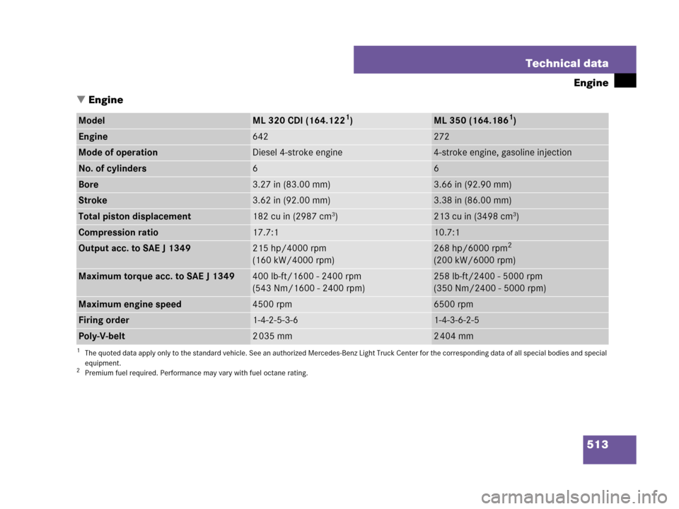
Engine
�Engine
ModelML 320 CDI (164.1221)
1The quoted data apply only to the standard vehicle. See an authorized Mercedes-Benz Light Truck Center for the corresponding data of all special bodies and special
equipment.
ML 350 (164.1861)
Engine642272
Mode of operationDiesel 4-stroke engine4-stroke engine, gasoline injection
No. of cylinders66
Bore3.27 in (83.00 mm)3.66 in (92.90 mm)
Stroke3.62 in (92.00 mm)3.38 in (86.00 mm)
Total piston displacement182 cu in (2987 cm3)213 cu in (3498 cm3)
Compression ratio17.7:110.7:1
Output acc. to SAE J 1349215 hp/4000 rpm
(160 kW/4000 rpm)268 hp/6000 rpm2
(200 kW/6000 rpm)
2Premium fuel required. Performance may vary with fuel octane rating.
Maximum torque acc. to SAE J 1349400 lb-ft/1600 - 2400 rpm
(543 Nm/1600 - 2400 rpm)258 lb-ft/2400 - 5000 rpm
(350 Nm/2400 - 5000 rpm)
Maximum engine speed4500 rpm6500 rpm
Firing order1-4-2-5-3-61-4-3-6-2-5
Poly-V-belt2 035 mm2 404 mm
Page 515 of 561

1All data preliminary. The quoted data apply only to the standard vehicle. See an authorized Mercedes-Benz Light Truck Center for the corresponding dat")
514 Technical data
Engine
ModelML 550 (164.1751)
1All data preliminary. The quoted data apply only to the standard vehicle. See an authorized Mercedes-Benz Light Truck Center for the corresponding data of all special
bodies and special equipment.
ML 63 AMG (164.1772)
2The quoted data apply only to the standard vehicle. See an authorized Mercedes-Benz Light Truck Center for the corresponding data of all special bodies and special
equipment.
Engine273156
Mode of operation4-stroke engine, gasoline injection4-stroke engine, gasoline injection
No. of cylinders88
Bore3.86 in (98.00 mm)4.02 in (102.20 mm)
Stroke3.56 in (90.50 mm)3.72 in (94.60 mm)
Total piston displacement333.2 cu in (5461 cm3)378.8 cu in (6208 cm3)
Compression ratio10.7:111.3:1
Output acc. to SAE J 1349382 hp/6000 rpm3
(285 kW/6000 rpm)
3Premium fuel required. Performance may vary with fuel octane rating.
503 hp/6800 rpm3
(375 kW/6800 rpm)
Maximum torque acc. to SAE J 1349391 lb-ft/2800 - 4800 rpm
(530 Nm/2800 - 4800 rpm)465 lb-ft/5200 rpm
(630 Nm/5200 rpm)
Maximum engine speed6500 rpm7200 rpm
Firing order1-5-4-2-6-3-7-81-5-4-2-6-3-7-8
Poly-V-belt2 404 mm2 360 mm