Page 484 of 561
483 Practical hints
Flat tire
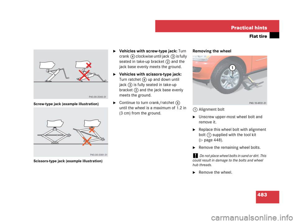
Screw-type jack (example illustration)
Scissors-type jack (example illustration)
�Vehicles with screw-type jack: Turn
crank4 clockwise until jack3 is fully
seated in take-up bracket2 and the
jack base evenly meets the ground.
�Vehicles with scissors-type jack:
Turn ratchet4 up and down until
jack3 is fully seated in take-up
bracket2 and the jack base evenly
meets the ground.
�Continue to turn crank/ratchet4
until the wheel is a maximum of 1.2 in
(3 cm) from the ground.Removing the wheel
1Alignment bolt
�Unscrew upper-most wheel bolt and
remove it.
�Replace this wheel bolt with alignment
bolt1 supplied with the tool kit
(
�page 448).
�Remove the remaining wheel bolts.
�Remove the wheel.
!Do not place wheel bolts in sand or dirt. This
could result in damage to the bolts and wheel
hub threads.
Page 488 of 561

487 Practical hints
Flat tire
Lowering the vehicle
�Vehicles with scissors-type jack:
Attach ratchet to vehicle jack in such a
way that the wordDOWN can be seen.
�Lower the vehicle until its resting fully
on its own weight.
�Vehicles with screw-type jack:
Turn crank counterclockwise.
�Vehicles with scissors-type jack:
Turn ratchet in Direction of DOWN.
�Remove the jack.1-5Wheel bolts
�Tighten the five wheel bolts evenly, fol-
lowing the diagonal sequence illustrat-
ed (1 to 5), until all bolts are tight.
Observe a tightening torque of
110 lb-ft (150 Nm).
�Store jack and all other vehicle tool kit
items back into the storage well.
Warning!G
Vehicles with collapsible tire
(ML 63 AMG only):
Inflate collapsible tire only after the wheel is
properly mounted.
Inflate the collapsible tire using the electric
pump (
�page 485) before lowering the
vehicle.
Warning!G
Have the tightening torque checked after
changing a wheel. The wheels could come
loose if they are not tightened to a torque of
110 lb-ft (150 Nm).
iThe removed road wheel cannot be stored in
the spare wheel well under the cargo compart-
ment floor, but should be transported in the car-
go compartment wrapped in a protective cover.
Vehicles with TPMS or Advanced TPMS*:
Do not activate the tire inflation pressure moni-
tor until a full size wheel/tire with functioning
sensor has been placed back into service on the
vehicle.
Page 497 of 561
.
�Connect the negative lead to the nega-
tive terminal (
�page 494).
Charging th")
496 Practical hints
Battery
�Connect the positive lead to the posi-
tive terminal and fasten it’s cover
(
�page 494).
�Connect the negative lead to the nega-
tive terminal (
�page 494).
Charging the battery
If the battery is discharged, the battery can
be charged using the jump-start contacts
located in the engine compartment
(
�page 498).
�Charge the battery in accordance with
the instructions of the battery charger
manufacturer.
Batteries contain materials that can harm
the environment if disposed of improperly.
Large 12-volt storage batteries contain
lead. Recycling of batteries is the preferred
method of disposal. Many states require
sellers of batteries to accept old batteries
for recycling.
!Never invert the terminal connections!
iThe following procedures must be carried
out following any interruption of battery power
(e.g. due to reconnection):
�Set the clock (�page 169).
Vehicles with COMAND system with naviga-
tion module*: Time and date are set auto-
matically.
�Synchronize the door windows
(
�page 237).
�Synchronize the power tilt/sliding sunroof
(
�page 242).
�Synchronize the power folding exterior rear
view mirrors* (
�page 200).
Warning!G
Never charge a battery while still installed in
the vehicle unless the accessory battery
charge unit approved by Mercedes-Benz is
being used. Gases may escape during charg-
ing and cause explosions that may result in
paint damage, corrosion or personal injury.
An accessory battery charge unit specially
adapted for Mercedes-Benz vehicles and
tested and approved by Mercedes-Benz is
available, permitting the charging of the
battery in its installed position. Contact an
authorized Mercedes-Benz Light Truck
Center for information and availability.
Charge battery in accordance with the
separate instructions for the accessory
battery charger.
��
Page 500 of 561

499 Practical hints
Towing the vehicle
�Towing the vehicle
Mercedes-Benz recommends that the
vehicle be transported with all wheels off
the ground using flatbed or appropriate
wheel lift/dolly equipment. This method is
preferable to other types of towing.If circumstances do not permit the recom-
mended towing methods, the vehicle may
be towed with all wheels on the ground
only so far as necessary to have the vehicle
moved to a safe location where the recom-
mended towing methods can be employed.
When towing the vehicle with all wheels on
the ground, the vehicle may be towed only
for distances up to 30 miles (50 km) and at
a speed not to exceed 30 mph (50 km/h).
!Do not tow-start the vehicle.
!Use flatbed or wheel lift/dolly equipment,
with the SmartKey in starter switch turned to
position0.
Do not tow with sling-type equipment. Towing
with sling-type equipment over bumpy roads will
damage radiator and supports.
To prevent damage during transport, do not tie
down vehicle by its chassis or suspension parts.
Use the towing eyes.
Switch off the ESP
® (�page 102) and the
automatic central locking (
�page 125).
!Do not tow with one axle raised. Doing so
could damage the transfer case, which is not
covered by the Mercedes-Benz Limited
Warranty.
All wheels must be on or off the ground. Observe
instructions for towing the vehicle with all
wheels on the ground.
Warning!G
If circumstances require towing the vehicle
with all wheels on the ground, always tow
with a tow bar if
�the engine will not run
�there is a malfunction in the brake
system
�there is a malfunction in the power
supply or in the vehicle’s electrical
system
This is necessary to adequately control the
towed vehicle.
Prior to towing the vehicle with all wheels on
the ground, make sure the automatic trans-
mission is in neutral positionN.
Page 503 of 561
502 Practical hints
Towing the vehicle
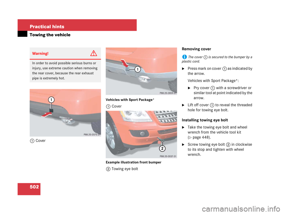
1Cover
Vehicles with Sport Package*
1Cover
Example illustration front bumper
2Towing eye boltRemoving cover
�Press mark on cover1 as indicated by
the arrow.
Vehicles with Sport Package*:
�Pry cover1 with a screwdriver or
similar tool at point indicated by the
arrow.
�Lift off cover1 to reveal the threaded
hole for towing eye bolt.
Installing towing eye bolt
�Take the towing eye bolt and wheel
wrench from the vehicle tool kit
(
�page 448).
�Screw towing eye bolt2 in clockwise
to its stop and tighten with wheel
wrench.
Warning!G
In order to avoid possible serious burns or
injury, use extreme caution when removing
the rear cover, because the rear exhaust
pipe is extremely hot.
iThe cover1 is secured to the bumper by a
plastic cord.
Page 504 of 561
503 Practical hints
Towing the vehicle
Removing towing eye bolt
�Loosen towing eye bolt2 counter-
clockwise with wheel wrench.
�Unscrew towing eye bolt2.
�Store the towing eye bolt and wheel
wrench back into the vehicle tool kit
(
�page 448).
Installing cover
�Engage cover1 at top and press at
bottom.
Stranded vehicle
Freeing a stranded vehicle, on which the
wheels are dug into sand or mud, should
be done with the greatest of care, especial-
ly if the vehicle is heavily loaded.
Avoid pulling the vehicle abruptly or diago-
nally, since it could result in damage to the
chassis alignment.
Never try to free a vehicle that is still cou-
pled to a trailer.
If possible, a vehicle equipped with trailer
hitch receiver should be pulled backward
in its own previously made tracks.
Page 506 of 561
505 Practical hints
Fuses
Fuse box in engine compartment
The fuse box is located on the passenger
side of the engine compartment.
�Open the hood (�page 341).
Example illustration fuse box ML 350
(ML 320 CDI, ML 550, ML 63 AMG similar)
1Fuse box cover
2Clamps
�Pull clamps2 in direction of arrow.
�Lift fuse box cover1 up.
�Install fuse box cover in reverse order.
�Close the hood after checking or
replacing fuses (
�page 343).
Fuse box in cargo compartment
The fuse box is located in the cargo com-
partment behind the passenger side trim
panel.
1Lock
2CoverRemoving/installing cover
�Open the tailgate (�page 119).
�Insert a suitable object such as a coin
into the slot of lock1 (
�page 505).
�Turn lock1 counterclockwise by 90°
in direction of arrow.
�Remove cover2.
�Install cover2 in reverse order.
!The fuse box cover must be installed
properly to prevent moisture and/or dirt from
entering the fuse box and possibly impairing fuse
operation.
Page 532 of 561

531 Index
A
ABS 98
Indicator lamp 400
Messages in the multifunction
display 415
Off-road - ABS 99
Accelerator position, automatic
transmission 190
Accessory weight 379
Accident 64
Active head restraint 88, 127, 458
Adaptive Damping System (ADS)* 255
Air bags 74
Children 75, 89
Front passenger front air bag off
indicator lamp 31, 83
Front, Driver 77
Front, Passenger 77
Occupant Classification System
(OCS) 79
Safety guidelines 76
Side impact (front and rear*) 78
Window curtain 78Air conditioning refrigerant 525
Air conditioning system see
Climate control or
Automatic climate control (3-zone)*
Air conditioning, Cooling 214, 229
Air distribution, Front 209, 224
Air distribution, Rear 217, 233
Air pressure see Tire inflation pressure
Air pump, electric (ML 63 AMG) 485
Air recirculation mode 212, 227
Air suspension program* 254
Adaptive Damping System
(ADS)* 255
Messages in the multifunction
display 447
Vehicle level control* 255
Air vents 217
Air vents, Front 210, 224
Air vents, Rear 234
Air volume 210, 225
Alarm system see Anti-theft systems
Alignment bolt (vehicle tool kit) 450, 483Anticorrosion/antifreeze 529
Antiglare, Interior rear view mirror 199
Antiglare, Rear view mirrors* 199
Antilock Brake System see ABS
Anti-theft systems 107
Anti-theft alarm system 106, 107
Immobilizer 106
Aquaplaning see Hydroplaning
Armrest storage/telephone* compart-
ment
Front 281
Ashtrays (Depending on vehicle
configuration) 285
Aspect ratio 379
ATF 345
Attaching a trailer 330
AUDIO menu 160
Audio menu
CD operation 161
Radio operation 160
Satellite radio* operation 160
Auto-dimming*, Rear view mirrors 199
Automatic central locking, Control
system 175