Page 280 of 561
279 Controls in detail
Useful features
�Useful features
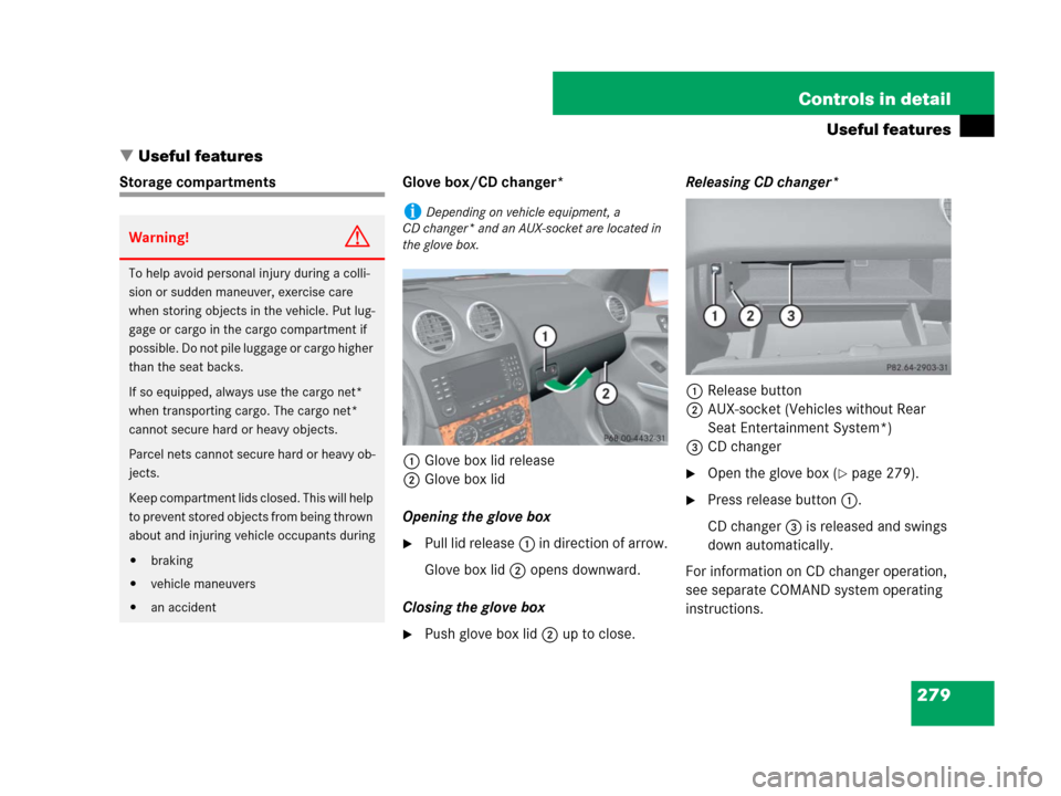
Storage compartments Glove box/CD changer*
1Glove box lid release
2Glove box lid
Opening the glove box
�Pull lid release1 in direction of arrow.
Glove box lid2 opens downward.
Closing the glove box
�Push glove box lid2 up to close.Releasing CD changer*
1Release button
2AUX-socket (Vehicles without Rear
Seat Entertainment System*)
3CD changer
�Open the glove box (�page 279).
�Press release button1.
CD changer3 is released and swings
down automatically.
For information on CD changer operation,
see separate COMAND system operating
instructions.
Warning!G
To help avoid personal injury during a colli-
sion or sudden maneuver, exercise care
when storing objects in the vehicle. Put lug-
gage or cargo in the cargo compartment if
possible. Do not pile luggage or cargo higher
than the seat backs.
If so equipped, always use the cargo net*
when transporting cargo. The cargo net*
cannot secure hard or heavy objects.
Parcel nets cannot secure hard or heavy ob-
jects.
Keep compartment lids closed. This will help
to prevent stored objects from being thrown
about and injuring vehicle occupants during
�braking
�vehicle maneuvers
�an accident
iDepending on vehicle equipment, a
CD changer* and an AUX-socket are located in
the glove box.
Page 286 of 561
285 Controls in detail
Useful features
Removing and reinstalling cup holder
The front cup holder can be removed for
cleaning purposes.
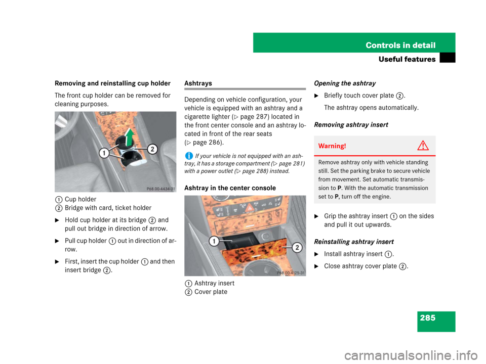
1Cup holder
2Bridge with card, ticket holder
�Hold cup holder at its bridge2 and
pull out bridge in direction of arrow.
�Pull cup holder1 out in direction of ar-
row.
�First, insert the cup holder1 and then
insert bridge2.
Ashtrays
Depending on vehicle configuration, your
vehicle is equipped with an ashtray and a
cigarette lighter (
�page 287) located in
the front center console and an ashtray lo-
cated in front of the rear seats
(
�page 286).
Ashtray in the center console
1Ashtray insert
2Cover plateOpening the ashtray
�Briefly touch cover plate2.
The ashtray opens automatically.
Removing ashtray insert
�Grip the ashtray insert1 on the sides
and pull it out upwards.
Reinstalling ashtray insert
�Install ashtray insert1.
�Close ashtray cover plate2.
iIf your vehicle is not equipped with an ash-
tray, it has a storage compartment (
�page 281)
with a power outlet (
�page 288) instead.
Warning!G
Remove ashtray only with vehicle standing
still. Set the parking brake to secure vehicle
from movement. Set automatic transmis-
sion toP. With the automatic transmission
set toP, turn off the engine.
Page 290 of 561

289 Controls in detail
Useful features
Power outlet in cargo compartment
�Switch on the ignition (�page 40).
�Flip up cover and insert electrical plug
(cigarette lighter type).
Floormats
1Retainer pin
2Eyelet
Removing
�Pull floormat off of retainer pins1.
�Remove the floormat.
Installing
�Lay down the floormat in the respective
footwell.
�Press the floormat eyelets2 onto re-
tainer pins1.
Warning!G
Whenever you are using floormats, make
sure there is enough clearance and that the
floormats are securely fastened.
Floormats should always be securely fas-
tened using eyelets2 and retainer pins1
(
�page 289).
Before driving off, check that the floormats
are securely in place and adjust them if nec-
essary. A loose floormat could slip and
hinder proper functioning of the pedals.
Do not place several floormats on top of
each other as this may impair pedal move-
ment.
iTo install or remove the floormat more easi-
ly, move the driver’s seat or front passenger seat
as far to the rear as possible (
�page 44).
Page 354 of 561

353 Operation
Tires and wheels
Seating capacity
The seating capacity gives you important
information on the number of occupants
that can be in the vehicle. Observe front
and rear seating capacity. The Tire and
Loading Information placard showing the
seating capacity is located on the driver’s
door B-pillar (
�page 352).
1Seating capacity information on the
Tire and Loading Information placard.
Steps for determining correct load limit
The following steps have been developed
as required of all manufacturers under
Title 49, Code of U.S. Federal Regulations,
Part 575 pursuant to the “National Traffic
and Motor Vehicle Safety Act of 1966”.Step 1
�Locate the statement “The combined
weight of occupants and cargo should
never exceed XXX kg or XXX lbs.” on
your vehicle’s Tire and Loading
Information placard.
Step 2
�Determine the combined weight of the
driver and passengers that will be
riding in your vehicle.
Step 3
�Subtract the combined weight of the
driver and passengers from
XXX kilograms or XXX lbs.
iData shown on Tire and Loading Information
placard example are for illustration purposes
only. Seating data are specific to each vehicle
and may vary from data shown in the illustration
below. Refer to Tire and Loading Information
placard on vehicle for actual data specific to your
vehicle.
��
Page 355 of 561

354 Operation
Tires and wheels
Step 4
�The resulting figure equals the avail-
able amount of cargo and luggage load
capacity. For example, if the “XXX”
amount equals 1400 lbs and there will
be five 150 lbs passengers in your
vehicle, the amount of available cargo
and luggage load capacity is 650 lbs
(1400-750 (5 x150) = 650 lbs).
Step 5
�Determine the combined weight of
luggage and cargo being loaded on the
vehicle. That weight may not safely
exceed the available cargo and luggage
load capacity calculated in step 4.Step 6 (if applicable)
�If your vehicle will be towing a trailer,
load from your trailer will be trans-
ferred to your vehicle. Consult this
manual to determine how this reduces
the available cargo and luggage load
capacity of your vehicle (
�page 356).
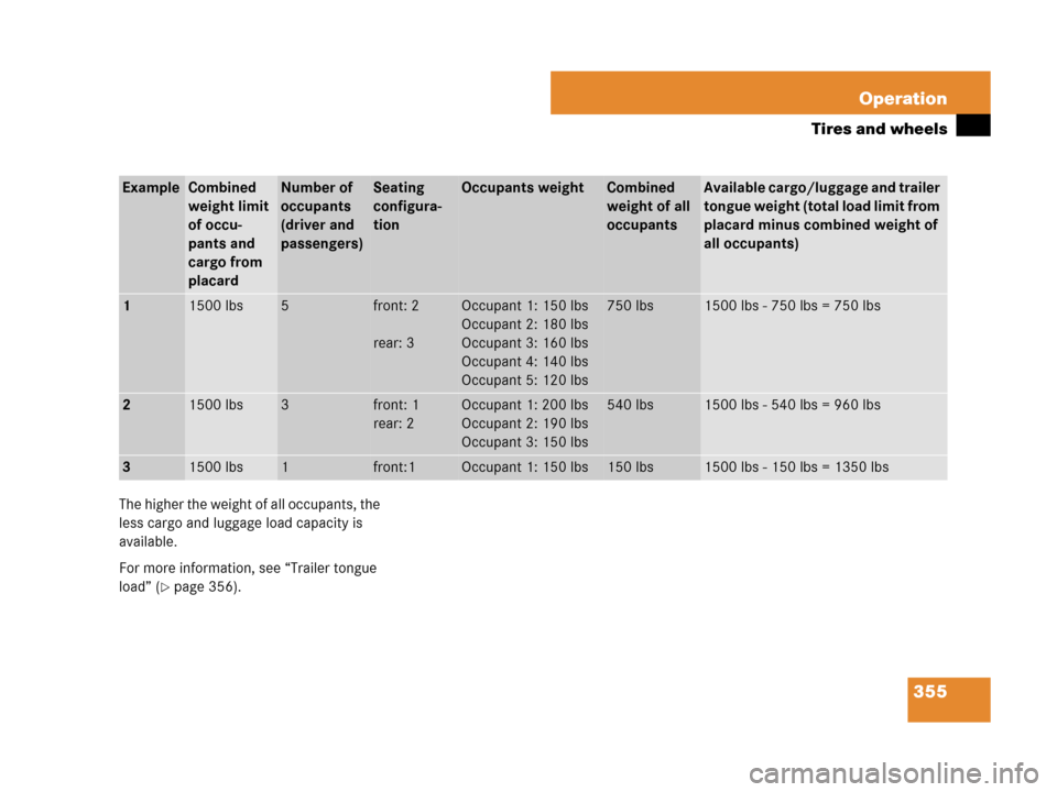
The following table shows examples on
how to calculate total and cargo load
capacities with varying seating configura-
tions and number and size of occupants.
The following examples use a load limit
of 1500 lbs. This is for illustration
purposes only. Make sure you are using
the actual load limit for your vehicle stated
on the vehicle’s Tire and Loading
Information placard (
�page 352).
��
Page 356 of 561
355 Operation
Tires and wheels
The higher the weight of all occupants, the
less cargo and luggage load capacity is
available.
For more information, see “Trailer tongue
load” (
�page 356).
ExampleCombined
weight limit
of occu-
pants and
cargo from
placardNumber of
occupants
(driver and
passengers)Seating
configura-
tionOccupants weight Combined
weight of all
occupantsAvailable cargo/luggage and trailer
tongue weight (total load limit from
placard minus combined weight of
all occupants)
11500 lbs5front: 2
rear: 3Occupant 1: 150 lbs
Occupant 2: 180 lbs
Occupant 3: 160 lbs
Occupant 4: 140 lbs
Occupant 5: 120 lbs750 lbs1500 lbs - 750 lbs = 750 lbs
21500 lbs3front: 1
rear: 2Occupant 1: 200 lbs
Occupant 2: 190 lbs
Occupant 3: 150 lbs540 lbs1500 lbs - 540 lbs = 960 lbs
31500 lbs1front:1Occupant 1: 150 lbs150 lbs1500 lbs - 150 lbs = 1350 lbs
Page 372 of 561

371 Operation
Tires and wheels
General:
Depending on the design standards used,
the tire size molded into the sidewall may
have no letter or a letter preceding the tire
size designation.
No letter preceding the size designation
(as illustrated above): Passenger car tire
based on European design standards.
Letter “P” preceding the size designation:
Passenger car tire based on U.S. design
standards.
Letter “LT” preceding the size designation:
Light Truck tire based on U.S. design
standards.
Letter “T” preceding the size designation:
Temporary spare tires which are high
pressure compact spares designed for
temporary emergency use only.Tire width
The tire width1 (
�page 370) indicates
the nominal tire width in mm.
Aspect ratio
The aspect ratio2 (
�page 370) is the
dimensional relationship between tire
section height and section width and is
expressed in percentage. The aspect ratio
is arrived at by dividing section height by
section width.
Tire code
The tire code3 (
�page 370) indicates
the tire construction type. The “R” stands
for radial tire type. Letter “D” means diag-
onal or bias ply construction; letter “B”
means belted-bias ply construction.
At the tire manufacturer’s option, any tire
with a speed capability above 149 mph
(240 km/h) can include a “ZR” in the size
designation (for example: 245/40 ZR 18).
For additional information, see “Tire speed
rating” (
�page 372).Rim diameter
The rim diameter4 (
�page 370) is the
diameter of the bead seat, not the
diameter of the rim edge. Rim diameter is
indicated in inches (in).
Tire load rating
The tire load rating5 (
�page 370) is a
numerical code associated with the
maximum load a tire can support.
For example, a load rating of 91 corre-
sponds to a maximum load of 1 356 lbs
(615 kg) the tire is designed to support.
See also “Maximum tire load”
(
�page 376) where the maximum load as-
sociated with the load index is indicated in
kilograms and lbs.
Page 382 of 561

381 Operation
Tires and wheels
Maximum load rating
The maximum load in kilograms and
pounds that can be carried by the tire.
Maximum loaded vehicle weight
The sum of curb weight, accessory weight,
total load limit and production options
weight.
Maximum tire inflation pressure
This number is the greatest amount of air
pressure that should ever be put in the tire
under normal driving conditions.
Normal occupant weight
The number of occupants the vehicle is
designed to seat, multiplied by
68 kilograms (150 lbs).
Occupant distribution
The distribution of occupants in a vehicle
at their designated seating positions.Production options weight
The combined weight of those installed
regular production options weighing over
5 lbs (2.3 kilograms) in excess of those
standard items which they replace, not
previously considered in curb weight or
accessory weight, including heavy duty
brakes, ride levelers, roof rack, heavy duty
battery, and special trim.
PSI (P
ounds per square inch)
A standard unit of measure for air pressure
-> bar, kilopascal (kPa).
Recommended tire inflation pressure
Recommended tire inflation pressure for
normal driving conditions is listed on the
Tire and Loading Information placard locat-
ed on driver’s door B-pillar. Provides best
handling, tread life and riding comfort. If so
equipped, supplemental information per-
taining to special driving situations can be
found on the tire inflation pressure label on
the inside of the fuel filler flap.Rim
A metal support for a tire or a tire and tube
assembly upon which the tire beads are
seated.
Sidewall
The portion of a tire between the tread and
the bead.
TIN (Tire Identification Number)
Unique identifier which facilitates efforts
by tire manufacturers to notify purchasers
in recall situations or other safety matters
concerning tires and gives purchases the
means to easily identify such tires. The TIN
is comprised of “Manufacturer’s identifica-
tion mark”, “Tire size”, “Tire type code”
and “Date of manufacture”.
Tire load rating
Numerical code associated with the
maximum load a tire can support.