Page 400 of 457

399
Practical hints
Towing the vehicle
� Towing the vehicle
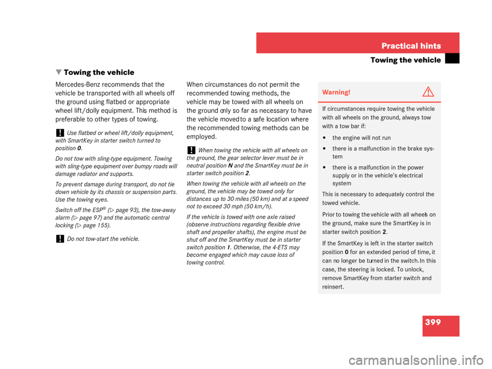
Mercedes-Benz recommends that the
vehicle be transported with all wheels off
the ground using flatbed or appropriate
wheel lift/dolly equipment. This method is
preferable to other types of towing. When circumstances do not permit the
recommended towing methods, the
vehicle may be towed with all wheels on
the ground only so far as necessary to have
the vehicle moved to a safe location where
the recommended towing methods can be
employed.
!Use flatbed or wheel lift/dolly equipment,
with SmartKey in starter switch turned to
position 0.
Do not tow with sling-type equipment. Towing
with sling-type equipment over bumpy roads will
damage radiator and supports.
To prevent damage during transport, do not tie
down vehicle by its chassis or suspension parts.
Use the towing eyes.
Switch off the ESP
® (�page 93), the tow-away
alarm (
�page 97) and the automatic central
locking (
�page 155).
!Do not tow-start the vehicle.
!When towing the vehicl e with all wheels on
the ground, the gear selector lever must be in
neutral position N and the SmartKey must be in
starter switch position 2.
When towing the vehicle with all wheels on the
ground, the vehicle may be towed only for
distances up to 30 miles (50 km) and at a speed
not to exceed 30 mph (50 km/h).
If the vehicle is towed with one axle raised
(observe instructions regarding flexible drive
shaft and propeller shafts ), the engine must be
shut off and the SmartKey must be in starter
switch position 1. Otherwise, the 4-ETS may
become engaged which may cause loss of
towing control.
Warning!G
If circumstances require towing the vehicle
with all wheels on the ground, always tow
with a tow bar if:
�the engine will not run
�there is a malfunction in the brake sys-
tem
�there is a malfunction in the power
supply or in the vehicle’s electrical
system
This is necessary to adequately control the
towed vehicle.
Prior to towing the vehicle with all wheels on
the ground, make sure the SmartKey is in
starter switch position 2.
If the SmartKey is left in the starter switch
position 0 for an extended period of time, it
can no longer be turned in the switch. In this
case, the steering is locked. To unlock,
remove SmartKey from starter switch and
reinsert.
W463.boo Seite 399 Montag, 19 . November 2007 8:41 08
Page 401 of 457

400 Practical hints
Towing the vehicle
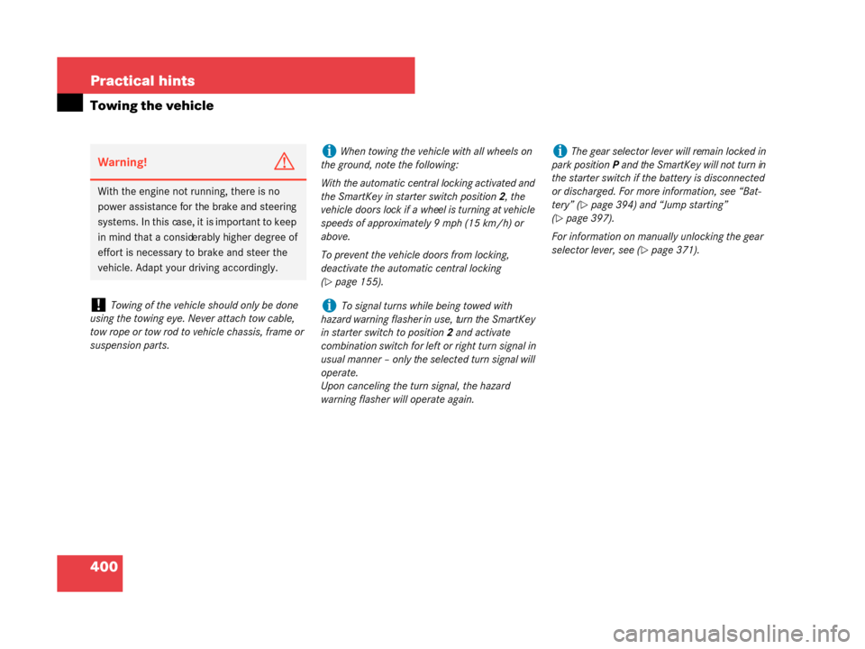
Warning!G
With the engine not running, there is no
power assistance for the brake and steering
systems. In this case, it is important to keep
in mind that a considerably higher degree of
effort is necessary to brake and steer the
vehicle. Adapt your driving accordingly.
!Towing of the vehicle should only be done
using the towing eye. Never attach tow cable,
tow rope or tow rod to vehicle chassis, frame or
suspension parts.
iWhen towing the vehicle with all wheels on
the ground, note the following:
With the automatic central locking activated and
the SmartKey in starter switch position 2, the
vehicle doors lock if a wheel is turning at vehicle
speeds of approximately 9 mph (15 km/h) or
above.
To prevent the vehicle doors from locking,
deactivate the automatic central locking
(
�page 155).
iTo signal turns while being towed with
hazard warning flasher in use, turn the SmartKey
in starter switch to position 2 and activate
combination switch for left or right turn signal in
usual manner – only the selected turn signal will
operate.
Upon canceling the turn signal, the hazard
warning flasher will operate again.
iThe gear selector lever will remain locked in
park position P and the SmartKey will not turn in
the starter switch if the battery is disconnected
or discharged. For more information, see “Bat-
tery” (
�page 394) and “Jump starting”
(
�page 397).
For information on manua lly unlocking the gear
selector lever, see (
�page 371).
W463.boo Seite 400 Montag, 19 . November 2007 8:41 08
Page 402 of 457

401
Practical hints
Towing the vehicle
Transporting the vehicle
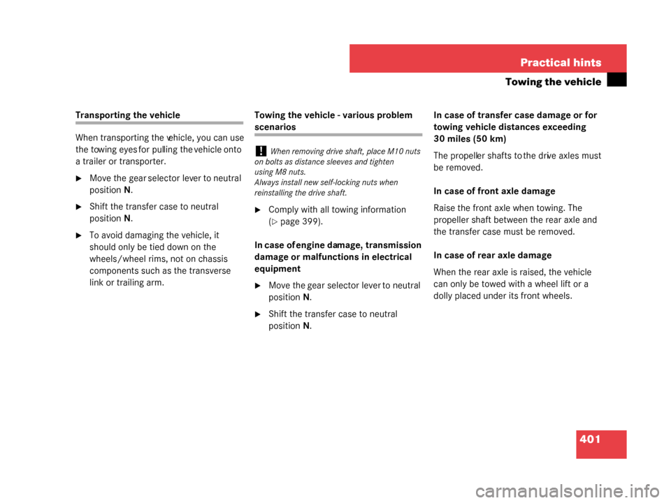
When transporting the vehicle, you can use
the towing eyes for pulling the vehicle onto
a trailer or transporter.
�Move the gear selector lever to neutral
position
N.
�Shift the transfer case to neutral
position N.
�To avoid damaging the vehicle, it
should only be tied down on the
wheels/wheel rims, not on chassis
components such as the transverse
link or trailing arm. Towing the vehicle - various problem
scenarios
�Comply with all towing information
(
�page 399).
In case of engine damage, transmission
damage or malfunctions in electrical
equipment
�Move the gear selector lever to neutral
position N.
�Shift the transfer case to neutral
position N. In case of transfer case damage or for
towing vehicle distances exceeding
30 miles (50 km)
The propeller shafts to
the drive axles must
be removed.
In case of front axle damage
Raise the front axle when towing. The
propeller shaft between the rear axle and
the transfer case must be removed.
In case of rear axle damage
When the rear axle is raised, the vehicle
can only be towed with a wheel lift or a
dolly placed under its front wheels.
!When removing drive shaft, place M10 nuts
on bolts as distance sleeves and tighten
using M8 nuts.
Always install new self-locking nuts when
reinstalling the drive shaft.
W463.boo Seite 401 Montag, 19 . November 2007 8:41 08
Page 404 of 457

403
Practical hints
Fuses
� Fuses
The electrical fuses in your vehicle serve to
switch off malfunctioning power circuits.
If a fuse is blown, the components and
systems secured by that fuse will stop
operating. If a newly inserted fuse blows again, have
the cause determined and rectified at an
authorized Mercedes-Benz Light Truck
Center.
The following aids are available to help you
replace fuses.
�Fuse chart
The fuse chart explains the fuse
allocation and fuse amperages.
The fuse chart is located in the main
fuse box in the passenger compart-
ment (
�page 404).
�Spare fuses
The spare fuses are located in the main
fuse box in the passenger compart-
ment (
�page 404).
�Fuse extractor
The fuse extractor is located in the
vehicle tool kit in the rear footwell
(
�page 364).The electrical fuses are located in different
fuse boxes:
�in the passenger compartment on the
driver’s side (
�page 404)
�in the front passenger footwell
(
�page 404)
�in the middle tunnel (�page 405)
�in the battery box (�page 406)
Before replacing fuses:
�Apply parking brake (�page 62).
�Make sure the gear selector lever is set
to park position P (
�page 162).
�Turn off all electrical consumers.
�Turn off the engine (�page 64).
�Remove the SmartKey from the starter
switch.
Warning!G
Only use fuses approved by Mercedes-Benz
with the specified amperage for the system
in question and do not attempt to repair or
bridge a blown fuse. Using other than
approved fuses or using repaired or bridged
fuses may cause an overload leading to a
fire, and/or cause damage to electrical
components and/or systems. Have the
cause determined and remedied at an
authorized Mercedes-Benz Light Truck
Center.
iA blown fuse must be replaced by an
appropriate spare fuse (recognizable by its color
or the fuse rating given on the fuse) of the
amperage recommended in the fuse chart. Any
Mercedes-Light Truck Center will be glad to
advise you on this subject.
W463.boo Seite 403 Montag, 19 . November 2007 8:41 08
Page 408 of 457
407
Technical data
Parts service
Warranty coverage
Identification labels
Layout of poly-V-belt drive
Engine
Rims and tires
Electrical system
Main dimensions, vehicle weights
and ratings
Fuels, coolants, lubricants, etc.
W463.boo Seite 407 Montag, 19. November 2007 8:41 08
Page 412 of 457
411
Technical data
Identification labels
4
VIN (on frame in front wheel house) 5VIN (on lower edge of windshield)Example illustration G 500
6Engine number (engraved on engine)
7 Emission control information label,
includes both federal and California
certification exhaust emission stan-
dards
iWhen ordering parts, please specify vehicle
identification and engine numbers.
W463.boo Seite 411 Montag, 19 . November 2007 8:41 08
Page 414 of 457

413
Technical data
Engine
� Engine
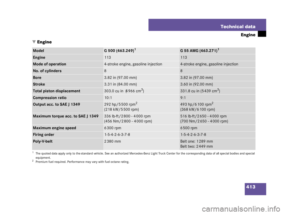
ModelG 500 (463.249)1
1The quoted data apply only to the standard vehicle. See an authorized Mercedes-Benz Light Truck Center for the corresponding da ta of all special bodies and special
equipment.
G 55 AMG (463.271)1
Engine113113
Mode of operation4-stroke engine, gasoline injection4-stroke engine, gasoline injection
No. of cylinders88
Bore3.82 in (97.00 mm)3.82 in (97.00 mm)
Stroke3.31 in (84.00 mm)3.60 in (92.00 mm)
Total piston displacement303.0cuin (4966cm3)331.8 cu in (5 439 cm3)
Compression ratio10:19:1
Output acc. to SAE J 1349292 hp/5 500 rpm2
(218 kW/5 500 rpm)
2Premium fuel required. Performance may vary with fuel octane rating.
493 hp/6 100 rpm2
(368 kW/6 100 rpm)
Maximum torque acc. to SAE J 1349336lb-ft/2800-4000rpm
(456 Nm/2 800 - 4 000 rpm)516 lb-ft/2 650 - 4 000 rpm
(700 Nm/2 650 - 4 000 rpm)
Maximum engine speed6 300 rpm6 500 rpm
Firing order1-5-4-2-6-3-7-81-5-4-2-6-3-7-8
Poly-V-belt2 380 mmBelt one: 1 289 mm
Belt two: 2 449 mm
W463.boo Seite 413 Montag, 19. November 2007 8:41 08
Page 422 of 457
421
Technical data
Fuels, coolants, lubricants, etc.
ModelCapacityFuels, coolants, lubricants, etc.
Engine with oil filterG500
G55AMG8.5 US qt (8.0 l)
9.0 US qt (8.5 l)Approved engine oils
Automatic transmission9.0 US qt (8.5 l)MB Automatic Transmission Fluid
Transfer case2.96 US qt (2.8 l)MB part no. A 001 989 28 03 10
Differential lock mechanism0.47-0.63USqt (0.45-0.6l)Brake fluid DOT 3+4, SAE J 1703
Front axleG500
G55AMG1.5 US qt (1.4 l)
1.5 US qt (1.4 l)Hypoid gear oil SAE 85W-90
Hypoid gear oil Castrol SAF-XJ
Rear axleG500
G55AMG1.9 US qt (1.8 l)
1.9 US qt (1.8 l)Hypoid gear oil SAE 85W-90
Hypoid gear oil Castrol SAF-XJ
Power steeringapprox. 1.06 US qt (1.0 l)MB Power Steering Fluid, or
approved Dexron III ATF
Front wheel hubsapprox. 1.5oz (43g) eachHigh temperature roller bearing grease
Brake system0.86 US qt (0.81 l)MB Brake Fluid (DOT 4+)
W463.boo Seite 421 Montag, 19
. November 2007 8:41 08