2008 MERCEDES-BENZ E-CLASS SALOON service reset
[x] Cancel search: service resetPage 15 of 401

12
Rear-view mirror
Adjustin g.. . . . . . . . . . . . . . . . . . . .91
Anti-dazzle (manual) . . . . . . . . . . . . .91
Anti-dazzle mode (automatic) . . . . .92
Rear window
Cleaning . . . . . . . . . . . . . . . . . . . . .246
Rear window blind . . . . . . . . . . . . . ..208
Rear window heating . . . . . . . . . . ..175
Malfunction indicator lamp . . . . . .283
Rear window wiper . . . . . . . . . . . . ..106
Replacing the wiper blade . . . . . . .316
Refuelling . . . . . . . . . . . . . . . . . . . . . .218
Remote control Auxiliary heating . . . . . . . . . . . . . .178
Changing the batteries (auxiliary
heating) . . . . . . . . . . . . . . . . . . . . .311
Garage door opene r.. . . . . . . . . . .214
Programming (garage door
opener) . . . . . . . . . . . . . . . . . . . . . .214
Replacing the wiper blades . . . . . ..315
Reserve Display message . . . . . . . . . . . . . .281
Reserve fuel . . . . . . . . . . . . . . . . . . . .378
Display message . . . . . . . . . . . . . .281
Fuel tank . . . . . . . . . . . . . . . . . . . .378
Warning lamp . . . . . . . . . . . . . . . . .291
Reset button . . . . . . . . . . . . . . . . . . .120
Restraint system Display message . . . . . . . . . . . . . .265 Restraint System
see SRS
Restraint systems
For children . . . . . . . . . . . . . . . . . . .48
Retaining hooks (boot) . . . . . . . . . ..195
Rev counter . . . . . . . . . . . . . . . . . . . .121
Reverse gear Engaging (automatic transmission) 115
Engaging (manual transmission) . .115
Reversing lamp
Display message . . . . . . . . . . . . . .276
Roller sunblind
Opening/closing . . . . . . . . . . . . . .184
Rear side window . . . . . . . . . . . . . .208
Rear window . . . . . . . . . . . . . . . . .208
Roof load, maximum
. . . . . . . . . . . . . .370, 371, 372, 373, 374
Roof rack . . . . . . . . . . . . . . . . . . . . . .187
Run-on time (mobile phone) . . . . . ..212 S
Safety net . . . . . . . . . . . . . . . . . . . . . .201
Seat Adjusting . . . . . . . . . . . . . . .77, 78, 80
Correct driver's seat position . . . . . .97
Storing settings . . . . . . . . . . . . . . . .93Seat belt
Adjusting the height . . . . . . . . . . . . .97
Fastening . . . . . . . . . . . . . . . . . . . . .95
Warning lamp . . . . . . . . . . . . . .97, 290
Seat cushion
Removing (rear bench seat) . .197, 200
Seat heating . . . . . . . . . . . . . . . . . . . . .85
Seat ventilation . . . . . . . . . . . . . . . . . .85
Malfunction indicator lamp . . . . . .282
Securing a load . . . . . . . . . . . . . . . . .191
Selector lever Display message . . . . . . . . . . . . . .261
Positions . . . . . . . . . . . . . . . . . . . .115
Service
Display message . . . . . . . . . . . . . .243
Service display
see ASSYST PLUS
Service indicator
see ASSYST PLUS
Service products . . . . . . . . . . . . . . . .377
Brake fluid . . . . . . . . . . . . . . . . . . .390
Coolant . . . . . . . . . . . . . . . . . . . . .388
Windscreen washer fluid . . . . . . . .390
Settings
Calling up a stored setting . . . . . . . .94
Factory (key ).. . . . . . . . . . . . . .66, 67
Factory (KEYLESS GO) . . . . . . . . . . .68
Factory (on-board computer) . . . . .132 Index
211_AKB; 2; 5, en-GB
mkalafa,
Version: 2.9.4 2008-02-29T16:57:07+01:00 - Seite 12Dateiname: 6515_3416_02_buchblock.pdf; preflight
Page 50 of 401
Occupant safety
47
If the seat belts are not released:
X
Move the backrest or the seat back slightly
until the belt tension is reduced.
The locking mechanism releases. G
Risk of injury
Make sure when adjusting the seat that
nobody can become trapped.
! Make sure that there are no objects in the
footwell or behind the seats when adjusting
the seats. You could otherwise damage the
seats and the objects. NECK-PRO head restraint
NECK-PRO head restraints are designed to
increase protection to the driver's and front-
passenger's head and neck. To this end, the
head restraints on the driver's and front-
passenger seats are moved forwards and
upwards in the event of a rear-end collision in
the direction of travel. This provides better
head support. G
Risk of injury
Head restraint covers prevent the NECK-
PRO head restraints from triggering cor-
rectly. Consequently, the NECK-PRO head restraints cannot provide the intended level
of protection. Do not use head restraint
covers.
If the NECK-PRO head restraints are triggered
in an accident, you must reset the head
restraints on the driver's and front-passenger
seats (Y page 309). Head restraints that have
been triggered are tilted forwards. Children in the vehicle
If a child is travelling in your vehicle, secure
the child using a child restraint system which
is appropriate to the size and age of the child
and recommended for Mercedes-Benz vehi-
cles. Preferably, you should fit the restraint
system to a suitable rear seat. Ensure that the
child is strapped in throughout the trip.
You can obtain information about the correct
child restraint system from any Mercedes-
Benz Service Centre.
i It is advisable to use Mercedes-Benz care
products to clean child restraint systems.
Information about this can be obtained
from any Mercedes-Benz Service Centre. G
Risk of injury
Do not leave children unsupervised in the
vehicle, even if they are secured in a child
restraint system. Children could injure
themselves on parts of the vehicle. They
could also be seriously or even fatally
injured by prolonged exposure to extreme
heat or cold.
Do not expose the child restraint system to
direct sunlight. The metallic parts of the
child restraint system could heat up and the
child could be burned by them.
If children open a door, they could injure
themselves and others. They could get out
and injure themselves or be injured by a
passing vehicle.
Please also observe the information on
HOLD. Relevant information can be found
in the index. G
Risk of injury
An unsecured or incorrectly positioned load
increases the risk of injury to the child in
the event of:
R an accident
R a braking manoeuvre
R a sudden change of direction Safety
211_AKB; 2; 5, en-GB
mkalafa,
Version: 2.9.4
2008-02-29T16:57:07+01:00 - Seite 47 ZDateiname: 6515_3416_02_buchblock.pdf; preflight
Page 123 of 401
Instrument cluster
120 Instrument cluster
Points to remember
You will find a full overview of the instrument
cluster in the "At a glance" section
(Y page 26). G
Risk of accident
No further messages can be displayed if the
instrument cluster and/or the multi-func-
tion display fails.
This means that you will not see information
about the driving situation, such as the
speed, outside temperature, warning/indi-
cator lamps, display messages or system
failures. The vehicle's handling character-
istics may be affected. Adjust your driving
style and speed accordingly.
Immediately consult a qualified specialist
workshop which has the necessary special-
ist knowledge and tools to carry out the
work required. Mercedes-Benz recom-
mends that you use a Mercedes-Benz
Service Centre for this purpose. In particu-
lar, work relevant to safety or on safety-
related systems must be carried out at a
qualified specialist workshop. Activating the multi-function display
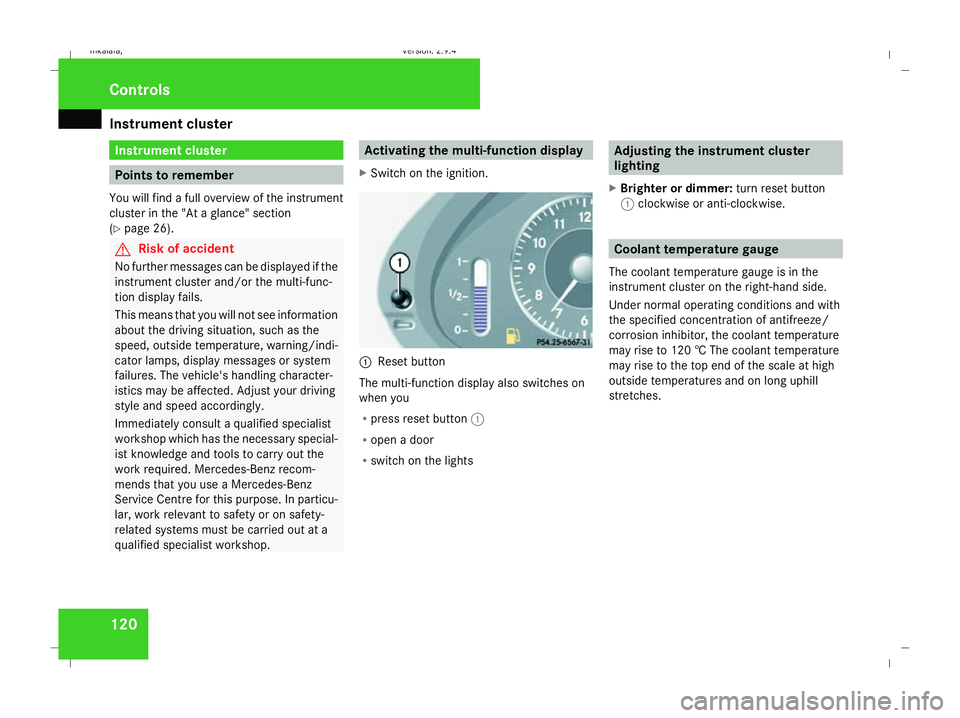
X Switch on the ignition. 1
Reset button
The multi-function display also switches on
when you
R press reset button 1
R open a door
R switch on the lights Adjusting the instrument cluster
lighting
X Brighter or dimmer: turn reset button
1 clockwise or anti-clockwise. Coolant temperature gauge
The coolant temperature gauge is in the
instrument cluster on the right-hand side.
Under normal operating conditions and with
the specified concentration of antifreeze/
corrosion inhibitor, the coolant temperature
may rise to 120 † The coolant temperature
may rise to the top end of the scale at high
outside temperatures and on long uphill
stretches. Controls
211_AKB; 2; 5, en-GB
mkalafa
, Version: 2.9.4 2008-02-29T16:57:07+01:00 - Seite 120Dateiname: 6515_3416_02_buchblock.pdf; preflight
Page 124 of 401
On-board computer
121Resetting the trip meter
X Select the standard display menu
(Y page 125).
X Press and hold reset button 1until the trip
meter is reset. Speedometer with segments
The segments in the speedometer indicate
which speed range is available.
Cruise control mode:
The segments light up from the stored speed
to the maximum speed.
Distronic* mode:
One or two segments around the stored
speed light up.
Variable Speedtronic mode:
The segments light up from the start of the
scale to the selected limit speed. Rev counter
The red band in the rev counter indicates the
engine's overrevving range. The fuel supply is
interrupted to protect the engine when the
red band is reached.
! Do not drive in the overrevving range.
Doing so will damage the engine. H
Environmental note
Avoid driving at high engine speeds, as this
increases your vehicle's consumption
unnecessarily and pollutes the environ-
ment through increased emissions. Outside temperature display
G
Risk of accident
The road surface may be icy, especially in
wooded areas or on bridges, even if tem-
peratures are just above freezing point. The
vehicle could skid if you fail to adapt your
driving style. You should therefore always
adapt your driving style and speed to suit
the weather conditions.
There is a short delay before a change in out-
side temperature is displayed. On-board computer
Points to remember
The on-board computer is activated as soon
as the key is turned to position 1in the igni-
tion lock. You can use the on-board computer
to call up information relating to your vehicle
and to make and adjust settings.
You can call up the next service due date,
select the display language for the instrument
cluster and set other functions. G
Risk of accident
Only use the on-board computer when road
and traffic conditions permit. You would
otherwise be distracted and unable to con-
centrate properly on driving, and could
cause an accident.
The on-board computer shows information in
the multi-function display. Controls
* optional
211_AKB; 2; 5, en-GB
mkalafa,
Version: 2.9.4
2008-02-29T16:57:07+01:00 - Seite 121 ZDateiname: 6515_3416_02_buchblock.pdf; preflight
Page 128 of 401

On-board computer
125Function
1 Basic display
menu (Ypage 125)
R Digital speedometer 17
(Y page 126)
R Outside tempera-
ture 17
(Y page 126)
R ASSYST PLUS service display
(Y page 243)
R Engine oil level* (Y page 223)
R Tyre pressure loss warning system
(Y page 230) or tyre pressure mon-
itor* (Y page 232) 2
AMG* menu (Y
page 126) 3
Audio/TV*/DVD*
(Ypage 129)
menu
R Radio station ( Ypage 129)
R Audio drive or media (Y page 129)
R TV* (Y page 130)
R DVD video* (Y page 130) Function
4
Navigation* menu (Y
page 130) 5
Distronic
* menu (distance display)
(Y page 145) 6
Message memory
menu18
(fault and
warning messages) (Y page 131) 7 Settings
menu (Ypage 131)
R Resetting to factory settings
(Y page 132)
R Selecting a submenu (Y page 132) 8 Trip computer
menu
R Consumption statistics
(Y page 140)
R Range (Y page 140) 9
Telephone*
menu (Ypage 141) This is what the displays look like when you
scroll through the menus.
The generic terms in the table overview are
intended to help you navigate through themenus. The terms themselves are not always
displayed in the multi-function display.
The Audio, Navi* and Tel* menus are dis-
played slightly differently in vehicles with
audio equipment and vehicles with COMAND
APS*. The examples given in this Owner's
Manual apply to vehicles equipped with
COMAND APS*. Standard display menu
i Menu overview: (Y page 124).
Use the buttons on the multi-function steer-
ing wheel.
X Press the èor· button to select the
basic display.
17 The sequence of the digital speedometer and the outside temperature display depends on the settings in the "Basic display" submenu.
18 This menu is only visible if there is a display message available. Controls
* optional
211_AKB; 2; 5, en-GB
mkalafa,
Version: 2.9.4
2008-02-29T16:57:07+01:00 - Seite 125 ZDateiname: 6515_3416_02_buchblock.pdf; preflight
Page 236 of 401

Tyres and wheels
233
Restarting the tyre pressure monitor In most cases, the tyre pressure monitor will
automatically detect the new reference val-
ues, e.g. if you have:
R
changed the tyre pressure
R changed the wheels or tyres
R fitted new wheels or tyres
If you wish to define the new reference values
manually:
X Use the table on the inside of the fuel filler
flap to ensure that the tyre pressure is set
correctly in all four tyres for the current
operating conditions.
Also observe the notes in the section on
tyre pressures (Y page 229).
X Make sure that the key is in position 2in
the ignition lock.
The standard display appears in the multi-
function display (Y page 125).
X Press the jork button to select the
Tyre pressure function or wait until the
following message appears:
Tyre pressure displayed only after
driving for a few minutes X
Press the reset button on the left of the
instrument cluster (Y page 243).
The following message appears in the
multi-function display: Check current
tyre pressure?
X Press the æbutton.
The following message appears in the
multi-function display:
Tyre pressure monitor restarted
The tyre pressure monitor has stored the
pressure of the tyres as a new reference
value.
If you wish to cancel the restart:
X Press the çbutton. Interchanging the wheels
G
Risk of accident
Interchange the front and rear wheels only
if they have the same dimensions: for exam-
ple size, offset, etc.
After every wheel interchange/change,
have the tightening torque checked at a
qualified specialist workshop that has the
necessary specialist knowledge and tools
to carry out the work required. Mercedes- Benz recommends that you use a
Mercedes-Benz Service Centre for this pur-
pose. In particular, work relevant to safety
or on safety-related systems must be car-
ried out at a qualified specialist workshop.
The wheels could work loose if they are not
tightened to a torque of 130 Nm.
For safety reasons, Mercedes-Benz recom-
mends that you only use wheel bolts of the
correct size which have been approved for
Mercedes-Benz vehicles.
The wheels may be interchanged every
5,000 km to 10,000 km depending on the
degree of tyre wear, provided that the vehicle
has the same size front and rear tyres. Do not
reverse the direction of tyre rotation.
The wear patterns on the front and rear tyres
differ depending on the operating conditions.
Interchange the wheels before a clear wear
pattern has formed on the tyres. The front
tyres typically wear more on the shoulders
and the rear tyres in the centre.
Clean the contact surfaces of the wheel and
the brake disc thoroughly every time a wheel
is interchanged. Check the tyre pressure and,
if necessary, restart the tyre pressure loss
warning system or the tyre pressure moni-
tor*. Operation
* optional
211_AKB; 2; 5, en-GB
mkalafa
,V ersion: 2.9.4
2008-02-29T16:57:07+01:00 - Seite 233 ZDateiname: 6515_3416_02_buchblock.pdf; preflight
Page 246 of 401
Service
243
Fitting the adapter
1
Connector with lug
2 Socket with groove
X Open the socket cover.
X Insert the connector with lug 1into
groove 2on the socket and turn the con-
nector clockwise to the stop.
X Make the cover engage.
X If you are using an adapter cable, secure
the cable to the trailer with cable ties.
! Make sure that there is sufficient cable
play so that the cable cannot become
detached when cornering. Service
Active Service System PLUS
ASSYST PLUS, the Active Service System,
tells you when the next service is due. When-
ever a service is due, this is shown in the
multi-function display:
Service A due in .. days
Service A due in .. km
Service A due now The letter indicates how much time the work-
shop will require to carry out the service work.
The letters displayed range from
Afor a short
service duration to Hfor a long service dura-
tion.
ASSYST PLUS does not record any periods of
time during which the battery is disconnec-
ted. In order to maintain the time-dependent
service schedule, you should call up the
service due date and make a note of it before
you disconnect the battery. The alternative is to subtract the battery-disconnection periods
from the service date shown on the display. Fading out the service message
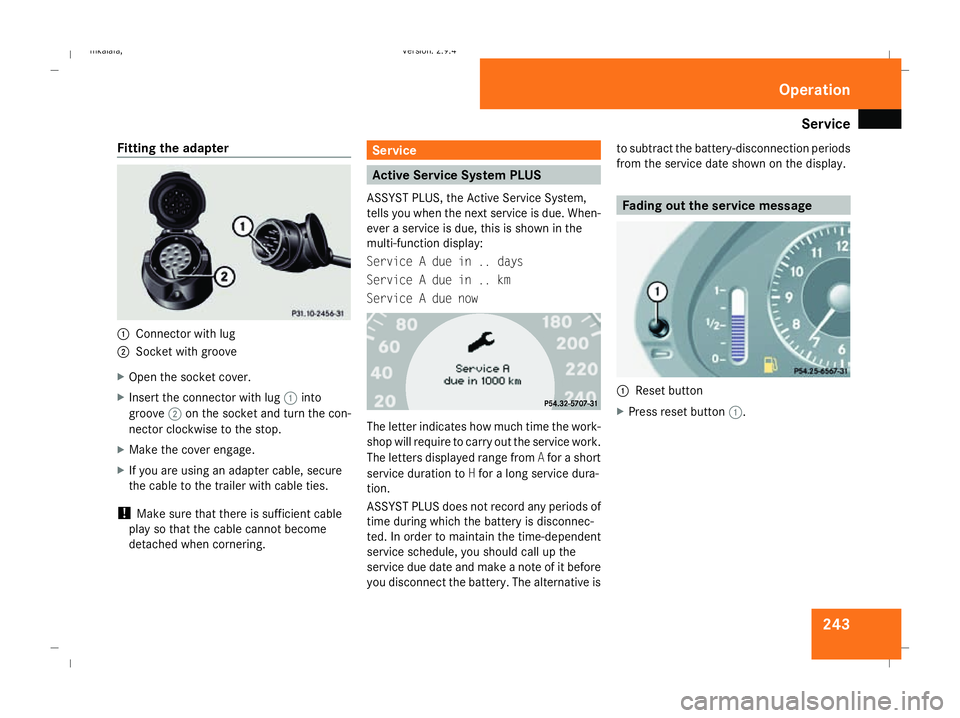
1
Reset button
X Press reset button 1. Operation
211_AKB; 2; 5, en-GB
mkalafa,
Version: 2.9.4
2008-02-29T16:57:07+01:00 - Seite 243 ZDateiname: 6515_3416_02_buchblock.pdf; preflight
Page 247 of 401
Care
244 Exceeding the service due date
One of the following messages appears in the
multi-function display:
Service A overdue by .. days
Service A overdue by .. km
You will also hear a warning tone.
A qualified specialist workshop, e.g. a
Mercedes-Benz Service Centre, will reset the
service indicator when it carries out the nec-
essary service work.
i If you fail to have the service performed
by the specified date, you may be contra-
vening the relevant laws, your warranty
may be invalidated and ex gratia claims
may be refused. Calling up the service due date
Use the buttons on the multi-function steer-
ing wheel.
X Switch on the ignition.
X Press èorÿ to select the Basic
display menu (Y page 125).
X Press jork to select the service
information.
The 9 service symbol and the service
due date are displayed.
X To select a different display, press j,
è orÿ. Care
Notes on care
Regular and proper care maintains the value
of your vehicle.
i It is advisable to use Mercedes-Benz care
products.
Scratches, corrosive deposits, areas affected
by corrosion and damage caused by inade-
quate care cannot always be completely
repaired. In such cases, visit a qualified spe-
cialist workshop immediately, e.g. a
Mercedes-Benz Service Centre.
Repair damage caused by loose chippings
and remove the following substances imme-
diately, whilst avoiding rubbing too hard:
R Soak insect remains with insect remover
and rinse off afterwards.
R Soak bird droppings with water and rinse
off afterwards.
R Remove tree resin, oils, fuels and greases
by rubbing gently with a cloth soaked in
petroleum ether or lighter fluid.
R Use silicone remover to remove wax.
R Use tar remover to remove tar stains. Operation
211_AKB; 2; 5, en-GB
mkalafa,
Version: 2.9.4 2008-02-29T16:57:07+01:00 - Seite 244Dateiname: 6515_3416_02_buchblock.pdf; preflight