2008 MERCEDES-BENZ E-CLASS SALOON buttons
[x] Cancel search: buttonsPage 215 of 401
Features
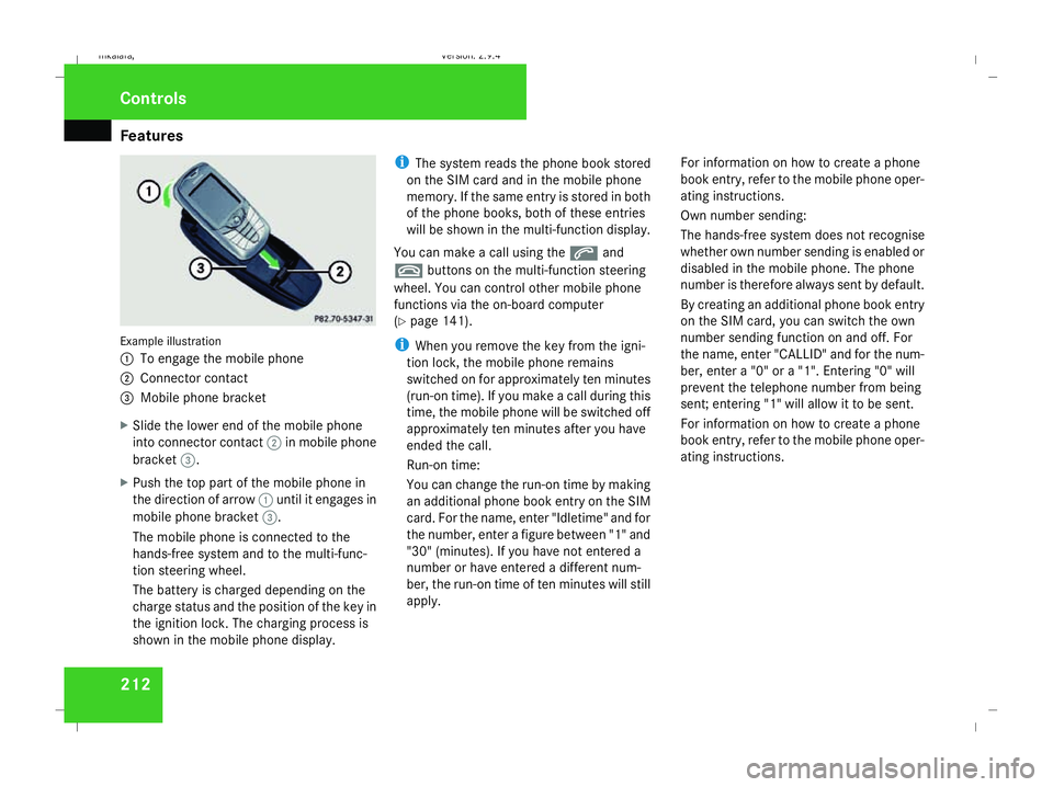
212Example illustration
1
To engage the mobile phone
2 Connector contact
3 Mobile phone bracket
X Slide the lower end of the mobile phone
into connector contact 2in mobile phone
bracket 3.
X Push the top part of the mobile phone in
the direction of arrow 1until it engages in
mobile phone bracket 3.
The mobile phone is connected to the
hands-free system and to the multi-func-
tion steering wheel.
The battery is charged depending on the
charge status and the position of the key in
the ignition lock. The charging process is
shown in the mobile phone display. i
The system reads the phone book stored
on the SIM card and in the mobile phone
memory. If the same entry is stored in both
of the phone books, both of these entries
will be shown in the multi-function display.
You can make a call using the sand
t buttons on the multi-function steering
wheel. You can control other mobile phone
functions via the on-board computer
(Y page 141).
i When you remove the key from the igni-
tion lock, the mobile phone remains
switched on for approximately ten minutes
(run-on time). If you make a call during this
time, the mobile phone will be switched off
approximately ten minutes after you have
ended the call.
Run-on time:
You can change the run-on time by making
an additional phone book entry on the SIM
card. For the name, enter "Idletime" and for
the number, enter a figure between "1" and
"30" (minutes). If you have not entered a
number or have entered a different num-
ber, the run-on time of ten minutes will still
apply. For information on how to create a phone
book entry, refer to the mobile phone oper-
ating instructions.
Own number sending:
The hands-free system does not recognise
whether own number sending is enabled or
disabled in the mobile phone. The phone
number is therefore always sent by default.
By creating an additional phone book entry
on the SIM card, you can switch the own
number sending function on and off. For
the name, enter "CALLID" and for the num-
ber, enter a "0" or a "1". Entering "0" will
prevent the telephone number from being
sent; entering "1" will allow it to be sent.
For information on how to create a phone
book entry, refer to the mobile phone oper-
ating instructions.Controls
211_AKB; 2; 5, en-GB
mkalafa,
Version: 2.9.4 2008-02-29T16:57:07+01:00 - Seite 212Dateiname: 6515_3416_02_buchblock.pdf; preflight
Page 218 of 401

Features
215
X
Erase the memory of the integrated remote
control (Y page 216) before programming
it for the first time.
X Turn the key to position 2in the ignition
lock.
X Press and hold one of transmitter buttons
2 to4 on the integrated remote control.
Indicator lamp 1starts to flash after a
short while. It flashes about once a second.
i Indicator lamp 1flashes immediately
the first time the transmitter button is pro-
grammed. If this transmitter button has
already been programmed, indicator
lamp 1will only start flashing at a rate of
once a second after 20 seconds have
elapsed.
X Keep the transmitter buttons depressed.
X Point the garage door's remote control with
the transmitter towards the left-hand side
of the rear-view mirror from a distance of 5
to 20 cm.
i The distance between the garage door's
remote control and the integrated garage
door opener depends on the system of the
garage door drive. You might require sev-
eral attempts. You should test every posi- tion for at least 20 seconds before trying
another position.
X Keep the transmitter button on the garage
door's remote control depressed until indi-
cator lamp 1starts to flash rapidly.
The programming was successful if indica-
tor lamp 1flashes rapidly.
X Release the transmitter buttons on the
garage door's remote control and the inte-
grated remote control.
If indicator lamp 1goes out after approxi-
mately 20 seconds and did not flash rapidly
before this:
X Release the transmitter buttons on the
integrated and portable remote controls.
X Repeat the programming procedure. At the
same time change the distance between
the garage door's remote control and the
transmitter buttons in the rear-view mirror.
i If the garage door system works with a
rolling code, after programming you must
synchronise the remote control integrated
in the rear-view mirror with the garage door
system receiver.
You will find further information in the
garage door opening system's operating instructions, e.g. the sections on “Synchro-
nising the transmitter” or “Registering a
new transmitter”. You can also call the hot-
line mentioned above.
Opening or closing the garage door Once programmed, the integrated remote
control will assume the function of the garage
door system's remote control. Please read
the operating instructions for the garage door
system.
X
Turn the key to position 2in the ignition
lock.
X Press the transmitter button on the rear-
view mirror that you have programmed to
operate the garage door.
Garage door system with fixed code: indi-
cator lamp 1lights up continuously.
Garage door system with rolling code: indi-
cator lamp 1flashes briefly and then lights
up for approximately two seconds. This is
repeated for up to 20 seconds.
i The transmitter will transmit a signal for
as long as the transmitter button is being
pressed. The transmission will be halted
after a maximum of 20 seconds and indi- Cont
rols
211_AKB; 2; 5, en-GB
mkalafa
,V ersion: 2.9.4
2008-02-29T16:57:07+01:00 - Seite 215 ZDateiname: 6515_3416_02_buchblock.pdf; preflight
Page 219 of 401
Features
216cator lamp
1will flash. Press the trans-
mitter button again if necessary.
Clearing the remote control memory X
Turn the key to position 2in the ignition
lock.
X Press and hold transmitter buttons 2and
4 for approximately 20 seconds until indi-
cator lamp 1flashes rapidly.
The memory is cleared.
i You should clear the remote control mem-
ory before selling the vehicle. Floormat* on the driver's side
G
Risk of accident
Make sure that there is sufficient clearance
around the pedals when floormats are
used, and that the floormats are properly
secured.
The floormats must be secured at all times
using retainers and studs.
Before you drive off, make sure that the
floormats are secure and rectify if neces-
sary. A floormat which is not properly secured can slip and thereby interfere with
the movement of the pedals.
Do not place floormats on top of one
another.
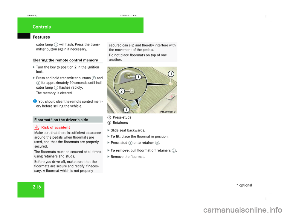
1
Press-studs
2 Retainers
X Slide seat backwards.
X To fit: place the floormat in position.
X Press stud 1onto retainer 2.
X To remove: pull floormat off retainers 2.
X Remove the floormat. Cont
rols
* optional
211_AKB; 2; 5, en-GB
mkalafa
,V ersion: 2.9.4
2008-02-29T16:57:07+01:00 - Seite 216 Dateiname: 6515_3416_02_buchblock.pdf; preflight
Page 247 of 401
Care
244 Exceeding the service due date
One of the following messages appears in the
multi-function display:
Service A overdue by .. days
Service A overdue by .. km
You will also hear a warning tone.
A qualified specialist workshop, e.g. a
Mercedes-Benz Service Centre, will reset the
service indicator when it carries out the nec-
essary service work.
i If you fail to have the service performed
by the specified date, you may be contra-
vening the relevant laws, your warranty
may be invalidated and ex gratia claims
may be refused. Calling up the service due date
Use the buttons on the multi-function steer-
ing wheel.
X Switch on the ignition.
X Press èorÿ to select the Basic
display menu (Y page 125).
X Press jork to select the service
information.
The 9 service symbol and the service
due date are displayed.
X To select a different display, press j,
è orÿ. Care
Notes on care
Regular and proper care maintains the value
of your vehicle.
i It is advisable to use Mercedes-Benz care
products.
Scratches, corrosive deposits, areas affected
by corrosion and damage caused by inade-
quate care cannot always be completely
repaired. In such cases, visit a qualified spe-
cialist workshop immediately, e.g. a
Mercedes-Benz Service Centre.
Repair damage caused by loose chippings
and remove the following substances imme-
diately, whilst avoiding rubbing too hard:
R Soak insect remains with insect remover
and rinse off afterwards.
R Soak bird droppings with water and rinse
off afterwards.
R Remove tree resin, oils, fuels and greases
by rubbing gently with a cloth soaked in
petroleum ether or lighter fluid.
R Use silicone remover to remove wax.
R Use tar remover to remove tar stains. Operation
211_AKB; 2; 5, en-GB
mkalafa,
Version: 2.9.4 2008-02-29T16:57:07+01:00 - Seite 244Dateiname: 6515_3416_02_buchblock.pdf; preflight
Page 260 of 401
Display
messages 257Display messages
Notes
The on-board computer shows warnings or
malfunctions in the multi-function display.
Certain display messages are accompanied
by a warning tone or a continuous tone.
The multi-function display shows high-priority
display messages in red. In the following
tables, these display messages are printed in
red.
Please respond in accordance with the dis-
play messages and follow the additional
notes in this Owner's Manual. G
Risk of accident
No further messages can be displayed if the
instrument cluster and/or the multi-func-
tion display fails.
This means that you will not see information
about the driving situation, such as the speed, outside temperature, warning/indi-
cator lamps, display messages or system
failures. The vehicle's handling character-
istics may be affected. Adjust your driving
style and speed accordingly.
Immediately consult a qualified specialist
workshop which has the necessary special-
ist knowledge and tools to carry out the
work required. Mercedes-Benz recom-
mends that you use a Mercedes-Benz
Service Centre for this purpose. In particu-
lar, work relevant to safety or on safety-
related systems must be carried out at a
qualified specialist workshop.
When you stop and park the vehicle, please
observe the instructions provided for HOLD
(Y page 155) and parking ( Ypage 113).
The following tables contain all the display
messages. Hiding display messages After a few seconds, the on-board computer
automatically hides some low priority display
messages. Other messages remain visible in
the multi-function display until you hide them
yourself.
Some high priority display messages cannot
be hidden. The multi-function display shows
these messages continuously until the cau-
ses of the messages have been remedied.
Use the buttons on the multi-function steer-
ing wheel.
X
Use the è,·,jork button
to select another display.
The on-board computer saves certain dis-
play messages in the message mem-
ory (Ypage 131). Practical advice
211_AKB; 2; 5, en-GB
mkalafa,
Version: 2.9.4
2008-02-29T16:57:07+01:00 - Seite 257 ZDateiname: 6515_3416_02_buchblock.pdf; preflight
Page 285 of 401
Troubleshooting
282 Troubleshooting
Points to remember
G
Risk of accident and injury
The operating safety of the vehicle could be impaired if service work is carried out incorrectly. There is a risk that you could lose control of
the vehicle and cause an accident. The safety systems may no longer be able to protect you or others as they are designed to do.
Always have maintenance work carried out at a qualified specialist workshop which has the necessary specialist knowledge and tools to
carry out the work required.
Mercedes-Benz recommends that you use a Mercedes-Benz Service Centre for this purpose.
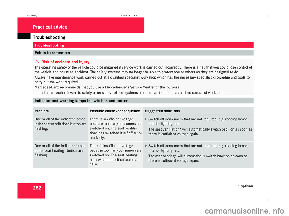
In particular, work relevant to safety or on safety-related systems must be carried out at a qualified specialist workshop. Indicator and warning lamps in switches and buttons
Problem Possible cause/consequence Suggested solutions
One or all of the indicator lamps
in the seat ventilation* button are
flashing. There is insufficient voltage
because too many consumers are
switched on. The seat ventila-
tion* has switched itself off auto-
matically. X
Switch off consumers that are not required, e.g. reading lamps,
interior lighting, etc.
The seat ventilation* will automatically switch back on as soon as
there is sufficient voltage again. One or all of the indicator lamps
in the seat heating* button are
flashing. There is insufficient voltage
because too many consumers are
switched on. The seat heating*
has switched itself off automati-
cally. X
Switch off consumers that are not required, e.g. reading lamps,
interior lighting, etc.
The seat heating* will automatically switch back on as soon as
there is sufficient voltage again. Practical advice
* optional
211_AKB; 2; 5, en-GB
mkalafa
,V ersion: 2.9.4
2008-02-29T16:57:07+01:00 - Seite 282 Dateiname: 6515_3416_02_buchblock.pdf; preflight
Page 314 of 401
Changing the bulbs
311
X
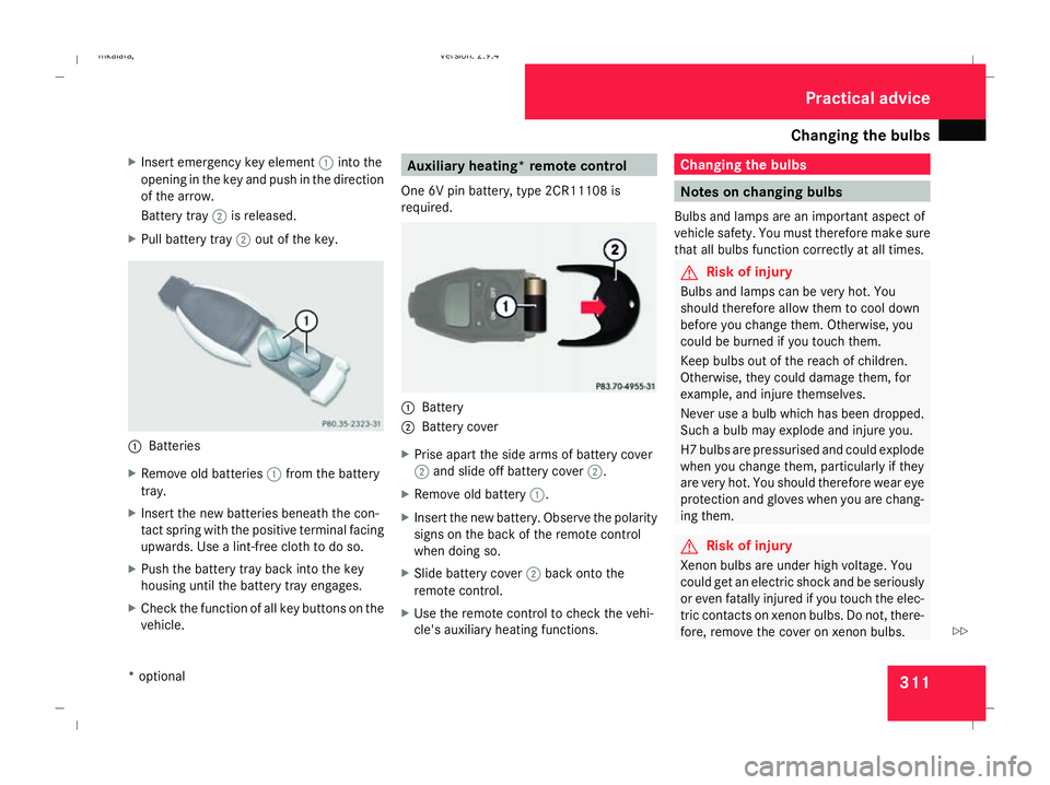
Insert emergency key element 1into the
opening in the key and push in the direction
of the arrow.
Battery tray 2is released.
X Pull battery tray 2out of the key. 1
Batteries
X Remove old batteries 1from the battery
tray.
X Insert the new batteries beneath the con-
tact spring with the positive terminal facing
upwards. Use a lint-free cloth to do so.
X Push the battery tray back into the key
housing until the battery tray engages.
X Check the function of all key buttons on the
vehicle. Auxiliary heating* remote control
One 6V pin battery, type 2CR11108 is
required. 1
Battery
2 Battery cover
X Prise apart the side arms of battery cover
2 and slide off battery cover 2.
X Remove old battery 1.
X Insert the new battery. Observe the polarity
signs on the back of the remote control
when doing so.
X Slide battery cover 2back onto the
remote control.
X Use the remote control to check the vehi-
cle's auxiliary heating functions. Changing the bulbs
Notes on changing bulbs
Bulbs and lamps are an important aspect of
vehicle safety. You must therefore make sure
that all bulbs function correctly at all times. G
Risk of injury
Bulbs and lamps can be very hot. You
should therefore allow them to cool down
before you change them. Otherwise, you
could be burned if you touch them.
Keep bulbs out of the reach of children.
Otherwise, they could damage them, for
example, and injure themselves.
Never use a bulb which has been dropped.
Such a bulb may explode and injure you.
H7 bulbs are pressurised and could explode
when you change them, particularly if they
are very hot. You should therefore wear eye
protection and gloves when you are chang-
ing them. G
Risk of injury
Xenon bulbs are under high voltage. You
could get an electric shock and be seriously
or even fatally injured if you touch the elec-
tric contacts on xenon bulbs. Do not, there-
fore, remove the cover on xenon bulbs. Practical advice
* optional
211_AKB; 2; 5, en-GB
mkalafa,
Version: 2.9.4 2008-02-29T16:57:07+01:00 - Seite 311 ZDateiname: 6515_3416_02_buchblock.pdf; preflight