2008 MERCEDES-BENZ A-CLASS HATCHBACK tow bar
[x] Cancel search: tow barPage 11 of 305

8
Indicator lamps
see Warning and indicator lamps
Instrument cluster............................... 97
Overview. .......................................... 26
Selecting the language (on-board
computer). ...................................... 108
Instrument lighting.............................. 97
Integrated child seat............................ 50
Interior lighting Automatic control system .................82
Delayed switch-off (on-board
computer). ...................................... 110
Emergency lighting. ..........................83
Manual control.................................. 82
Reading lamp .................................... 82
Interior motion sensor......................... 58
ISOFIX child seat securing system..... 48J
Jack...................................................... 200 Operation........................................ 259
Jump-starting ...................................... 266
Jump leads ...................................... 266K
Key......................................................... 60 Changing the battery ......................244
Checking the battery ......................244
Display message ............................. 220Loss.
............................................... 239
Malfunction..................................... 239
Modifying the programming. .............60
Key positions
Key. .................................................. 62
Kickdown.............................................. 96 L
Lamps see Warning and indicator lamps
Lashing eyelets.................................. 146
Licence plate lighting Display message ............................. 218
Light bulbs
see Bulbs
Lighting
see Lights
Lights
Automatic headlamp mode. ..............78
Constant headlamp mode. ................78
Cornering light function ....................81
Dipped-beam headlamps ..................78
Display messages ........................... 216
Foglamps. ......................................... 79
Hazard warning lamps. .....................80
Headlamp flasher.............................. 80
Headlamp range. .............................. 80
Light switch. ..................................... 77
Main-beam headlamps..................... .80
Rear fog lamp ................................... 79Switching off (display message)...... 218
Turn signals.
..................................... 79
LIM indicator lamp
Cruise control. ................................ 116
Variable Speedtronic. .....................118
Load compartment load, maximum
..................................................... 288, 289
Loading guidelines............................. 145
Locking Automatic. ........................................ 61
Emergency locking .........................242
From the inside (central locking
button) .............................................. 61
Luggage compartment enlarge-
ment.................................................... 150
Luggage compartment floor Adjusting the height .......................155
stowage well, unde r........................ 154
Luggage cover.................................... 159
Luggage net........................................ 145
Lumbar support.................................... 68 M
Main-beam headlamps Display message ............................. 218
Main fuse box..................................... 271
Maintenance Battery ............................................ 263Index
169_AKB; 2; 4, en-GB
wdomann,
Version: 2.10.6
2008-07-16T08:52:06+02:00 - Seite 8 Dateiname: 6515_0315_02_buchblock.pdf; preflight
Page 70 of 305

Seats
671
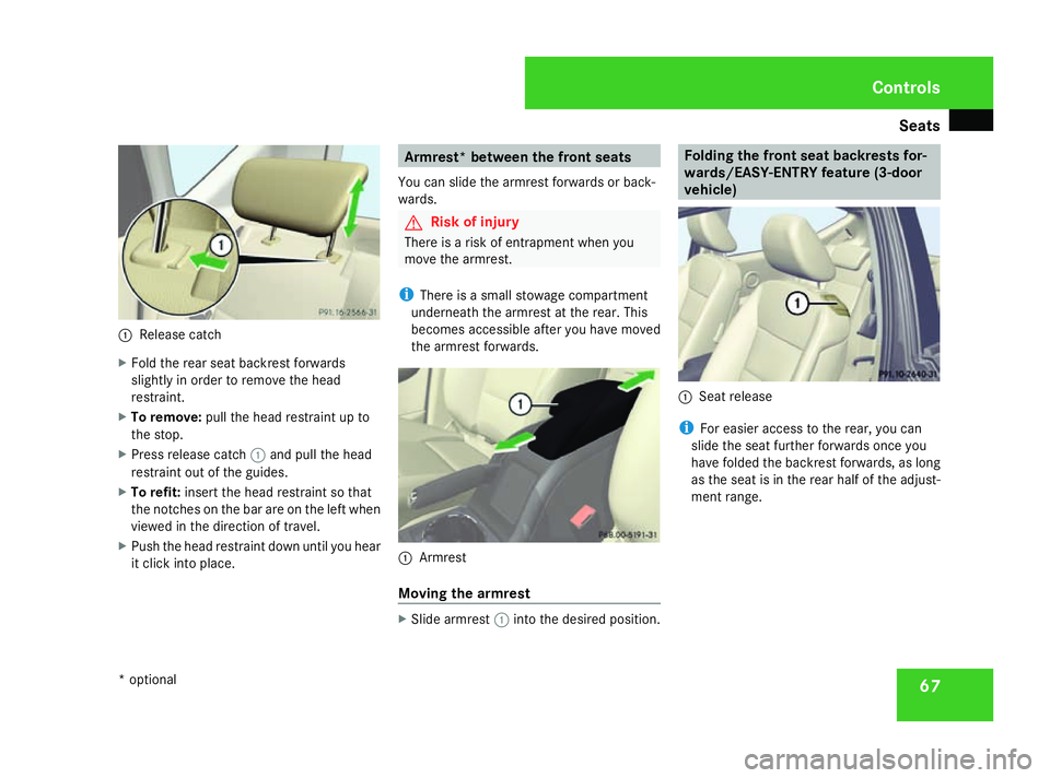
Release catch
X Fold the rear seat backrest forwards
slightly in order to remove the head
restraint.
X To remove: pull the head restraint up to
the stop.
X Press release catch 1and pull the head
restraint out of the guides.
X To refit: insert the head restraint so that
the notches on the bar are on the left when
viewed in the direction of travel.
X Push the head restraint down until you hear
it click into place. Armrest* between the front seats
You can slide the armrest forwards or back-
wards. G
Risk of injury
There is a risk of entrapment when you
move the armrest.
i There is a small stowage compartment
underneath the armrest at the rear. This
becomes accessible after you have moved
the armrest forwards. 1
Armrest
Moving the armrest X
Slide armrest 1into the desired position. Folding the front seat backrests for-
wards/EASY-ENTRY feature (3-door
vehicle) 1
Seat release
i For easier access to the rear, you can
slide the seat further forwards once you
have folded the backrest forwards, as long
as the seat is in the rear half of the adjust-
ment range. Controls
* optional
169_AKB; 2; 4, en-GB
wdomann,
Version: 2.10.6 2008-07-16T08:52:06+02:00 - Seite 67 ZDateiname: 6515_0315_02_buchblock.pdf; preflight
Page 124 of 305

Driving sys
tems 1211
Example: sensors in the front bumper,
left-hand side
Range of the sensors The sensors must be free of dirt, ice and
slush, otherwise they may not function cor-
rectly. Clean the sensors regularly, taking
care not to scratch or damage them
(Y
page 196). Side view Top view
Front sensors
Centre Approximately 100 cm
Corners Approximately 80 cm
Rear sensors
Centre Approximately 120 cm
Corners Approximately 80 cm
!
When parking, pay particular attention to
objects above or below the sensors, such
as flower pots or trailer towbars. Parktronic
does not detect such objects when they are
in the immediate vicinity of the vehicle. You
could damage the vehicle or the objects. Ultrasonic sources such as an automatic
car wash, a lorry's compressed-air brakes
or a pneumatic drill could cause Parktronic
to malfunction.
Minimum distance Centre Approximately 20 cm
Corners Approximately 20 cm
If there is an obstacle within this range, all
warning displays light up and a tone sounds.
If the distance falls below the minimum clear-
ance, it may no longer be shown.
Warning displays
The warning displays show the distance
between the sensors and the obstacle. The
warning display for the front area is located
on the dashboard above the centre air vents.
The warning display for the rear area is loca-
ted on the roof lining in the rear compart-
ment. Controls
169_AKB; 2; 4, en-GB
wdomann,
Version: 2.10.6
2008-07-16T08:52:06+02:00 - Seite 121 ZDateiname: 6515_0315_02_buchblock.pdf; preflight
Page 127 of 305

Driving sys
tems 124
Use Active parking assist for parking spaces
R that are parallel to the direction of travel.
R that are on straight roads, not bends.
R that are on the same level as the road, i.e.
not on the pavement, for example;
Parking tips:
R On narrow roads, drive as close to the park-
ing space as possible.
R Parking spaces which are littered, over-
grown or partially occupied by trailer tow-
bars might not be identified properly.
R Snowfall or heavy rain may lead to a parking
space being measured inaccurately.
R Pay attention to the Parktronic warning
messages during the parking procedure
(Y page 121).
R You can intervene in the steering procedure
to correct it at any time. Active parking
assist will then be cancelled.
R When transporting a load which protrudes
from your vehicle you should not use Active
parking assist.
R Never use active parking assist when snow
chains or an emergency spare wheel* are
fitted. R
Make sure that the tyre pressures are
always correct. This has a direct influence
on the parking characteristics of the vehi-
cle.
R The way your vehicle is positioned in the
parking space after parking is dependent
on various factors. These include the posi-
tion and shape of the vehicles parked in
front and behind it as well as the condition
of the location. In some cases, Active park-
ing assist may guide you too far into a park-
ing space, or not far enough into it. In some
cases it may also lead you across or onto
the kerb. If necessary, you should abort the
parking procedure with Active parking
assist.
R You can also engage forward gear prema-
turely. The vehicle redirects and does not
drive as far into the parking space Should
a gear be changed too early to achieve a
sensible parking position, the parking pro-
cedure will be aborted.
! When unavoidable, you should drive over
obstacles such as kerbs slowly and not at
a sharp angle. Otherwise you may damage
the wheel rims or tyres. Detecting parking spaces Active parking assist is switched on automat-
ically when driving forwards. The system is
operational at speeds of up to approximately
35 km/h. While in operation, the system inde-
pendently locates and measures parking
spaces on both sides of the vehicle. When
driving at speeds below 35 km/h, you will see
the parking symbol as a status indicator in the
instrument cluster. Active parking assist only
displays parking spaces on the front-
passenger side as standard. Parking spaces
on the driver's side are displayed as soon as
the turn signal on the driver's side is activa-
ted. If you wish to park in a space on the driv-
er's side, the indicator on the driver's side
must remain on. This must remain switched
on until you acknowledge the use of Active
parking assist by pressing the
jbutton on
the multi-function steering wheel.
When a parking space has been detected, an
arrow towards the right or the left also
appears. Controls
* optional
169_AKB; 2; 4, en-GB
wdomann,
Version: 2.10.6
2008-07-16T08:52:06+02:00 - Seite 124 Dateiname: 6515_0315_02_buchblock.pdf; preflight
Page 191 of 305

Trailer towing*
1881
Trailer power socket
X Fold trailer power socket 1down. G
Risk of accident
The ball coupling is only securely mounted
when the green mark on the handwheel is
aligned with the green area on the ball cou-
pling and the key can be removed. If the ball
coupling is not securely mounted, it may
come loose.
The ball coupling must be locked and the
key must be removed when towing a trailer.
This is the only way to guarantee that the
ball coupling is secured and cannot come
loose while the vehicle is in motion. If the
ball coupling cannot be locked and the key
cannot be removed, remove the ball cou-
pling and clean it. If the ball coupling can still not be fitted
(locked) after it has been cleaned, remove
the ball coupling. The trailer coupling must
then not be used to tow a trailer, as safe
operation is not guaranteed.
Have the entire trailer coupling checked at
a qualified specialist workshop. Mercedes-
Benz recommends that you use a
Mercedes-Benz Service Centre for this pur-
pose. In particular, work relevant to safety
or on safety-related systems must be car-
ried out at a qualified specialist workshop.
Notes on towing a trailer
G
Risk of accident
When reversing the vehicle towards the
trailer, make sure there is nobody between
the trailer and the vehicle.
Couple and uncouple the trailer carefully. If
you do not couple the trailer to the towing
vehicle correctly, the trailer could become
detached.
Make sure that the following values are not
exceeded: R
the permissible trailer drawbar nose-
weight
R the permissible trailer load
R the permissible rear axle load of the tow-
ing vehicle
R the maximum permissible gross vehicle
weight of both the towing vehicle and the
trailer
You will find the applicable permissible val-
ues, which must not be exceeded, in the
vehicle documents.
You will find the values approved by the
manufacturer on the vehicle identification
plates and those for the towing vehicle in
the "Technical data" section.
You will find installation dimensions and loads
in the "Technical data" section
(Y page 290).
The maximum permissible trailer drawbar
noseweight on the ball coupling is 75 kg.
However, the actual drawbar load must not
exceed the value given on the trailer coupling
and trailer identification plates. The lowest
weight applies.
! Use a noseweight as close as possible to
the maximum permissible noseweight. Do Operation
* optional
169_AKB; 2; 4, en-GB
wdomann,
Version: 2.10.6
2008-07-16T08:52:06+02:00 - Seite 188 Dateiname: 6515_0315_02_buchblock.pdf; preflight
Page 192 of 305

Trailer towing*
189
not use a noseweight of less than 50 kg,
otherwise the trailer may come loose.
Bear in mind that the payload and the rear
axle load are reduced by the actual nose-
weight.
i The height of the ball coupling changes
with the load of the vehicle. If necessary,
use a trailer with a height-adjustable draw-
bar.
Coupling up a trailer G
Risk of injury
Do not connect a trailer with an engaged
overrun brake. Otherwise, your hand could
become trapped between the bumper and
drawbar.
! Do not disconnect a trailer with an
engaged overrun brake. Otherwise your
vehicle could be damaged by the spring
action of the overrun brake.
X Position the trailer level behind the vehicle.
X Couple up the trailer.
X Establish the electrical connection
between the vehicle and the trailer. Driving tips In Germany, the maximum permitted speed
for vehicle/trailer combinations is 80 km/h.
G
Risk of accident
A maximum speed of 80 km/h should not
be exceeded, even in countries where
higher speeds are permitted for vehicle/
trailer combinations. This lowers the risk of
an accident.
When towing a trailer, your vehicle's handling
characteristics will be different in comparison
to when driving without a trailer.
The vehicle/trailer combination:
R is heavier
R is restricted in its acceleration and gradi-
ent-climbing capability
R has an increased braking distance
R is affected more by strong crosswinds
R demands more sensitive steering
R consumes more fuel
On long and steep downhill gradients, you
must select a lower gear in good time, or in
vehicles with AUTOTRONIC*, select shift
range 1,2or 3. i
This also applies if you have activated
cruise control* or Speedtronic*.
This will use the braking effect of the engine,
so less braking will be required to maintain
the speed. This relieves the load on the brake
system and prevents the brakes from over-
heating and wearing too quickly. If you need
additional braking, depress the brake pedal
repeatedly rather than continuously. G
Risk of accident
Never depress the brake pedal continu-
ously while the vehicle is in motion, e.g.
never cause the brakes to rub by applying
constant slight pedal pressure. This causes
the brake system to overheat, increases
the braking distance and can lead to the
brakes failing completely.
Driving tips
R Maintain a greater distance from the vehi-
cle in front than when driving without a
trailer.
R Avoid braking abruptly. If possible, brake
gently at first to allow the trailer to run on.
Then increase the braking force rapidly.
R The values given for gradient-climbing
capabilities from a standstill refer to sea
level. When driving in mountainous areas, Operation
* optional
169_AKB; 2; 4, en-GB
wdomann,
Version: 2.10.6 2008-07-16T08:52:06+02:00 - Seite 189 ZDateiname: 6515_0315_02_buchblock.pdf; preflight
Page 259 of 305

Flat tyre
256 ommends that you use a Mercedes-Benz
Service Centre for this purpose. In particu-
lar, work relevant to safety or on safety-
related systems must be carried out at a
qualified specialist workshop.
If a tyre pressure of 1.8 bar is reached:
X Press on/off switch 4on the electric air
pump to 0.
The electric air pump is switched off.
X Disconnect the electric air pump and stow
it away.
X Fold up the warning triangle and stow it
away.
X Pull away immediately.
This distributes the TIREFIT more evenly
around the tyre.
X Stop after driving for approximately ten
minutes and check the tyre pressure with
the electric air pump. G
Risk of accident
If the tyre pressure is now lower than
1.3 bar, the tyre is too badly damaged. Do
not drive any further. Consult a qualified
specialist workshop which has the neces-
sary specialist knowledge and tools to carry
out the work required. Mercedes-Benz rec-
ommends that you use a Mercedes-Benz Service Centre for this purpose. In particu-
lar, work relevant to safety or on safety-
related systems must be carried out at a
qualified specialist workshop.
X If the tyre pressure is still at least 1.3 bar,
correct it (see fuel filler flap for values).
To increase the tyre pressure: switch on
the electric air pump.
To reduce the tyre pressure: open pres-
sure release screw aon pressure
gauge b.
X Drive to the nearest workshop and have the
tyre changed there.
X Have the TIREFIT kit replaced as soon as
possible at a qualified specialist workshop,
e.g. at a Mercedes-Benz Service Centre. G
Risk of accident
Do not exceed the maximum speed of
80 km/h.
The "max. 80 km/h "sticker must be affixed
within the driver's field of vision.
The vehicle's handling characteristics may
be affected. H
Environmental note
Have the used TIREFIT kit disposed of pro-
fessionally, e.g. at a Mercedes-Benz
Service Centre.
X Have the TIREFIT kit replaced every four
years at a qualified specialist workshop,
e.g. a Mercedes-Benz Service Centre.
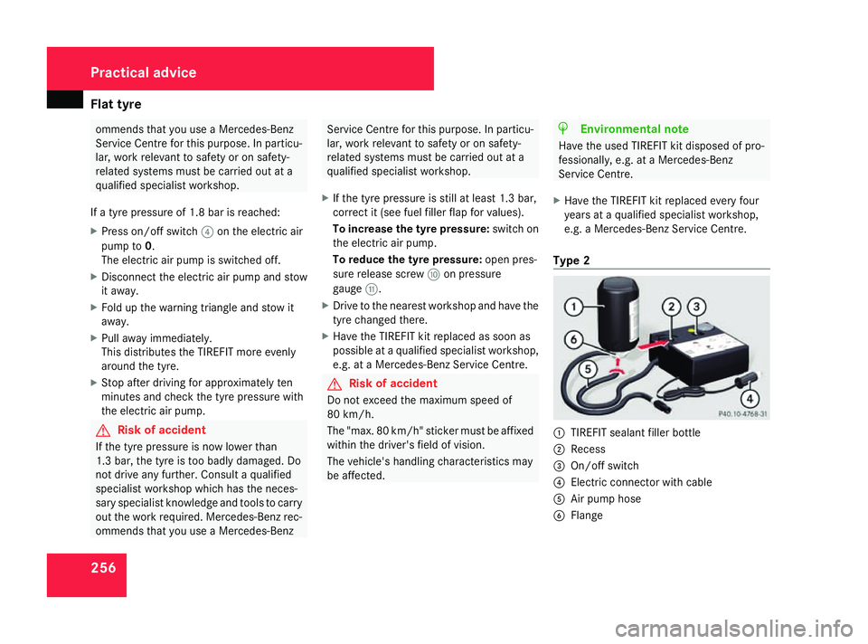
Type 2 1
TIREFIT sealant filler bottle
2 Recess
3 On/off switch
4 Electric connector with cable
5 Air pump hose
6 Flange Practical advice
169_AKB; 2; 4, en-GB
wdomann,
Version: 2.10.6 2008-07-16T08:52:06+02:00 - Seite 256Dateiname: 6515_0315_02_buchblock.pdf; preflight
Page 260 of 305

Flat tyre
257
X
Pull connector 4and air pump hose 5
from the housing.
X Screw air pump hose 5onto flange 6of
TIREFIT filler bottle 1.
X Place TIREFIT sealant filler bottle 1head
downwards into recess 2of the electric
air pump. 7
Valve
8 Filler hose
X Remove the cap from valve 7on the faulty
tyre.
X Screw filler hose 8onto valve 7. X
Insert plug 4into the socket of the ciga-
rette lighter* (Y page 163) or into a 12 V
power socket in your vehicle .
X Turn the key to position 2(Y page 62) in
the ignition lock.
X Press on/off switch 3on the electric air
pump to I.
The electric air pump is switched on. The
tyre is inflated.
i First, TIREFIT is pumped into the tyre. The
pressure can briefly rise to around 5 bar.
Do not switch off the electric pump dur-
ing this phase.
X Let the electric pump run for five minutes.
The tyre should then have a pressure of at
least 1.8 bar.
! Do not operate the electric air pump for
longer than eight minutes at a time without
a break. Otherwise, it may overheat.
The air pump can be operated again once
it has cooled down. If a pressure of 1.8 bar is not reached after
five minutes:
X Switch off and disconnect the electric air
pump and drive the vehicle forwards or
backwards approximately 10 m.
This distributes the TIREFIT more evenly.
X Remove TIREFIT sealant filler bottle 1
from the electric pump.
X Pump up the tyre again. G
Risk of accident
If a pressure of 1.8 bar is not achieved after
five minutes, the tyre is too badly damaged.
Do not drive any further. Consult a qualified
specialist workshop which has the neces-
sary specialist knowledge and tools to carry
out the work required. Mercedes-Benz rec-
ommends that you use a Mercedes-Benz
Service Centre for this purpose. In particu-
lar, work relevant to safety or on safety-
related systems must be carried out at a
qualified specialist workshop.
If a tyre pressure of 1.8 bar is reached:
X Press on/off switch 3on the electric air
pump to 0.
The electric air pump is switched off.
X Disconnect the electric air pump and stow
it away. Practical advice
* optional
169_AKB; 2; 4, en-GB
wdomann
, Version: 2.10.6 2008-07-16T08:52:06+02:00 - Seite 257 ZDateiname: 6515_0315_02_buchblock.pdf; preflight