2008 MERCEDES-BENZ A-CLASS HATCHBACK height
[x] Cancel search: heightPage 78 of 305

Seat belts
75
X
Route the belt over the centre of the shoul-
der without twisting it.
X Engage belt tongue 2into buckle 3.
X 5-door vehicle: if necessary, adjust the
belt to the appropriate height
(Y page 75).
X 3-door vehicles: make sure that swivelling
belt guide 5is in the correct position.
X All: if necessary, pull upwards on the shoul-
der section of the belt to tighten the belt
across your body.
Routing the belt X
Press release button 4and guide belt
tongue 2back towards belt sash guide
1. Belt warning for driver and front
passenger
The < seat belt warning lamp in the instru-
ment cluster reminds you that all passengers
should fasten their seat belts. It may light up
continuously or flash. Additionally, there may
be a warning tone.
The < seat belt warning lamp goes out and
the acoustic signal ceases as soon as the
driver and passenger have fastened their seat
belts.
For certain countries only: regardless of
whether the driver or the front passenger
already have their seat belt fastened, the
< seat belt warning lamp lights up for six
seconds after the engine has been started. It
then goes out when the driver and front
passenger have already fastened their seat
belts.
i Further information about the
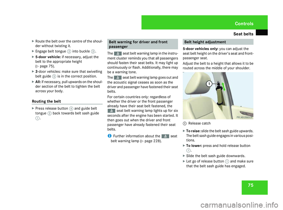
5-door vehicles only: you can adjust the
seat belt height on the driver's seat and front-
passenger seat.
Adjust the belt to a height that allows it to be
routed across the middle of your shoulder. 1
Release catch
X To raise: slide the belt sash guide upwards.
The belt sash guide engages in various posi-
tions.
X To lower: press and hold release button
1.
X Slide the belt sash guide downwards.
X Let go of release button 1and make sure
that the belt sash guide has engaged. Controls
169_AKB; 2; 4, en-GB
wdomann,
Version: 2.10.6
2008-07-16T08:52:06+02:00 - Seite 75 ZDateiname: 6515_0315_02_buchblock.pdf; preflight
Page 126 of 305

Driving sys
tems 123
i
Parktronic is automatically activated
when you turn the key to position 2in the
ignition lock.
Trailer towing* Parktronic is deactivated for the rear area
when you establish an electrical connection
between your vehicle and a trailer.
!
Remove the detachable trailer coupling if
it is no longer required. Parktronic meas-
ures the minimum detection range to an
obstacle from the bumper, not the ball cou-
pling. Active parking assist*
Active parking assist is an electronic parking
aid with ultrasound. Ultrasound is used to
measure the road on both sides of the vehicle.
A suitable parking space is indicated by the
parking symbol. Active steering intervention
can assist you during parking. You may also
use Parktronic (Y page 120). When Parktronic
is deactivated, active parking assist is also
unavailable. G
Risk of accident
Active parking assist is merely an aid and
may sometimes recommend parking
spaces that are not suitable for parking.
These might be, for example, spaces where
parking is prohibited, driveways, unsuitable
surfaces, etc.
Active parking assist measures the parking
space as you drive past it. Any later
changes to the parking space are not taken
into account. This may be the case, for
instance, when the vehicle parked in front
of or behind the space changes its position
or when an obstacle is moved into the park-
ing space.
Active parking assist does not relieve you
of the responsibility of paying attention. If
you rely solely on Active parking assist, you
could cause an accident and injure yourself
and others.
You are always responsible for safety and
must continue to pay attention to your
immediate surroundings when parking and
manoeuvring. G
Risk of accident
Objects located above the height range of
Active parking assist will not be detected when the parking space is measured. These
are not taken into account when the park-
ing procedure is calculated, e. g. overhang-
ing loads, tail sections or loading ramps of
goods vehicles. In some circumstances,
Active parking assist may therefore guide
you into the parking space too early. This
may lead to a collision. For this reason, you
should avoid using Active parking assist in
such situations.
G
Risk of accident
The front of the vehicle will veer out in the
direction of the oncoming traffic during the
parking operation. In some cases the vehi-
cle will also take you onto sections of the
oncoming lane during the parking proce-
dure.
You are responsible for safety at all times
and must pay attention to any road users
approaching or passing. Stop the vehicle if
necessary or cancel the Active parking
assist parking procedure. G
Risk of injury
Make sure that no persons or animals are
in the manoeuvring range. Otherwise, they
could be injured. Controls
* optional
169_AKB; 2; 4, en-GB
wdomann,
Version: 2.10.6 2008-07-16T08:52:06+02:00 - Seite 123 ZDateiname: 6515_0315_02_buchblock.pdf; preflight
Page 158 of 305

Loading and stowing
155
X
To fit: insert the luggage compartment
floor into the guide rail at an angle of
approximately 45°.
X Fold the luggage compartment floor down.
Opening/closing the luggage compart-
ment floor (vehicles with variable lug-
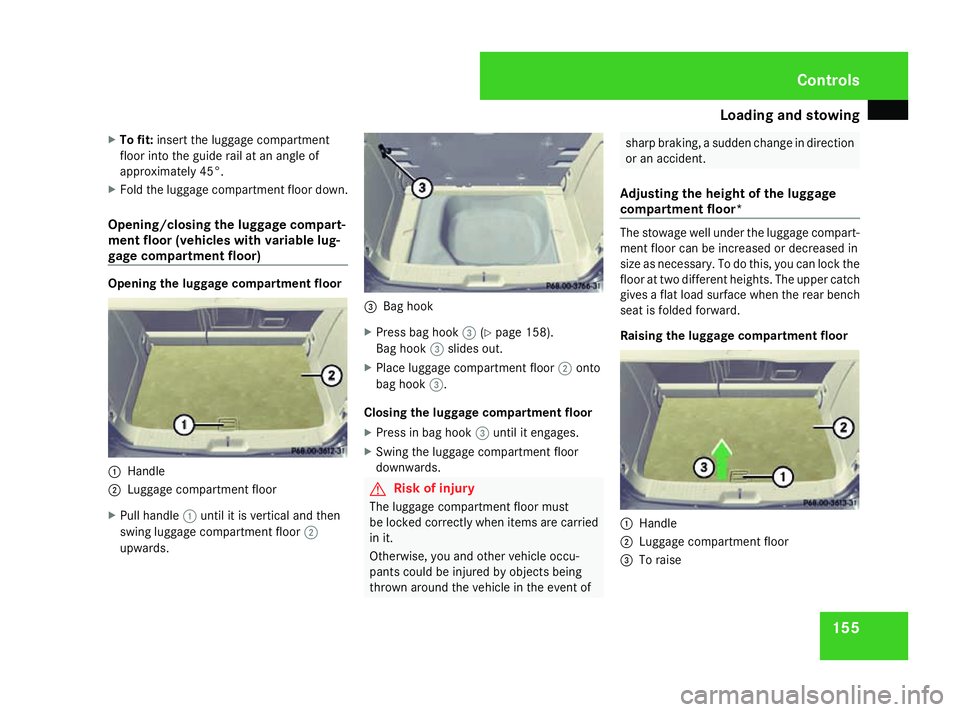
gage compartment floor) Opening the luggage compartment floor
1
Handle
2 Luggage compartment floor
X Pull handle 1until it is vertical and then
swing luggage compartment floor 2
upwards. 3
Bag hook
X Press bag hook 3(Ypage 158).
Bag hook 3slides out.
X Place luggage compartment floor 2onto
bag hook 3.
Closing the luggage compartment floor
X Press in bag hook 3until it engages.
X Swing the luggage compartment floor
downwards. G
Risk of injury
The luggage compartment floor must
be locked correctly when items are carried
in it.
Otherwise, you and other vehicle occu-
pants could be injured by objects being
thrown around the vehicle in the event of sharp braking, a sudden change in direction
or an accident.
Adjusting the height of the luggage
compartment floor* The stowage well under the luggage compart-
ment floor can be increased or decreased in
size as necessary. To do this, you can lock the
floor at two different heights. The upper catch
gives a flat load surface when the rear bench
seat is folded forward.
Raising the luggage compartment floor
1
Handle
2 Luggage compartment floor
3 To raise Controls
169_AKB; 2; 4, en-GB
wdomann,
Version: 2.10.6 2008-07-16T08:52:06+02:00 - Seite 155 ZDateiname: 6515_0315_02_buchblock.pdf; preflight
Page 175 of 305

Engine compartment
172
The handle for opening the bonnet is located
above the radiator grille. 2
Bonnet catch handle
X Pull handle 2of the bonnet catch out-
wards from the radiator grille and lift the
bonnet from underneath by the radiator
grille. 3
Recess
4 Support strut
5 Bracket
X Pull support strut 4out of bracket 5.
X Swing support strut 4upwards and insert
it into yellow recess 3.
Closing G
Risk of injury
Make sure that nobody can become trap-
ped as you close the bonnet.
X Raise the bonnet slightly and remove sup-
port strut 4from yellow recess 3.
X Swing support strut 4down and press it
into bracket 5until it engages. X
Lower the bonnet and let it fall from a
height of approximately 20 cm.
X Check that the bonnet has engaged prop-
erly.
i If the bonnet can be raised slightly, it is
not properly engaged. Open it again and
close it with a little more force. Engine oil
Depending on driving style, the vehicle con-
sumes a maximum of 0.8 l oil per 1,000 km.
The oil consumption may be higher than this
when the vehicle is new or if you frequently
drive at high engine speeds. You can only
estimate the oil consumption after you have
driven a considerable distance.
For further information on engine oil see
(Y page 296). Operation
169_AKB; 2; 4, en-GB
wdomann,
Version: 2.10.6 2008-07-16T08:52:06+02:00 - Seite 172Dateiname: 6515_0315_02_buchblock.pdf; preflight
Page 192 of 305

Trailer towing*
189
not use a noseweight of less than 50 kg,
otherwise the trailer may come loose.
Bear in mind that the payload and the rear
axle load are reduced by the actual nose-
weight.
i The height of the ball coupling changes
with the load of the vehicle. If necessary,
use a trailer with a height-adjustable draw-
bar.
Coupling up a trailer G
Risk of injury
Do not connect a trailer with an engaged
overrun brake. Otherwise, your hand could
become trapped between the bumper and
drawbar.
! Do not disconnect a trailer with an
engaged overrun brake. Otherwise your
vehicle could be damaged by the spring
action of the overrun brake.
X Position the trailer level behind the vehicle.
X Couple up the trailer.
X Establish the electrical connection
between the vehicle and the trailer. Driving tips In Germany, the maximum permitted speed
for vehicle/trailer combinations is 80 km/h.
G
Risk of accident
A maximum speed of 80 km/h should not
be exceeded, even in countries where
higher speeds are permitted for vehicle/
trailer combinations. This lowers the risk of
an accident.
When towing a trailer, your vehicle's handling
characteristics will be different in comparison
to when driving without a trailer.
The vehicle/trailer combination:
R is heavier
R is restricted in its acceleration and gradi-
ent-climbing capability
R has an increased braking distance
R is affected more by strong crosswinds
R demands more sensitive steering
R consumes more fuel
On long and steep downhill gradients, you
must select a lower gear in good time, or in
vehicles with AUTOTRONIC*, select shift
range 1,2or 3. i
This also applies if you have activated
cruise control* or Speedtronic*.
This will use the braking effect of the engine,
so less braking will be required to maintain
the speed. This relieves the load on the brake
system and prevents the brakes from over-
heating and wearing too quickly. If you need
additional braking, depress the brake pedal
repeatedly rather than continuously. G
Risk of accident
Never depress the brake pedal continu-
ously while the vehicle is in motion, e.g.
never cause the brakes to rub by applying
constant slight pedal pressure. This causes
the brake system to overheat, increases
the braking distance and can lead to the
brakes failing completely.
Driving tips
R Maintain a greater distance from the vehi-
cle in front than when driving without a
trailer.
R Avoid braking abruptly. If possible, brake
gently at first to allow the trailer to run on.
Then increase the braking force rapidly.
R The values given for gradient-climbing
capabilities from a standstill refer to sea
level. When driving in mountainous areas, Operation
* optional
169_AKB; 2; 4, en-GB
wdomann,
Version: 2.10.6 2008-07-16T08:52:06+02:00 - Seite 189 ZDateiname: 6515_0315_02_buchblock.pdf; preflight
Page 263 of 305

Flat tyre
2601
Wheel wrench
X Using wheel wrench 1, loosen the bolts on
the wheel you wish to change by about one
full turn. Do not unscrew the bolts com-
pletely.
Raising the vehicle G
Risk of injury
The jack is designed only to raise the vehi-
cle for a short time while a wheel is being
changed.
The vehicle must be placed on stands if you
intend to work under it.
Make sure that the jack is placed on a firm,
non-slip, level surface. Do not use wooden
blocks or similar objects as a jack underlay. Otherwise, the jack will not be able to ach-
ieve its load-bearing capacity due to the
restricted height.
Do not start the engine at any time while
the wheel is being changed.
Do not lie under the vehicle when it is being
supported by the jack. If you do not raise
the vehicle as described, it could slip off the
jack (e.g. if the engine is started or a door
or the tailgate is opened or closed) and you
could be seriously injured. G
Risk of accident
If you fail to position the jack correctly, the
vehicle may:
R slip off the jack
R injure you or others
R be damaged
Thus, it is important to make sure that the
jack is positioned correctly in the respec-
tive jacking points. Before positioning the
jack, remove any dirt that may have collec-
ted in the jacking points.
The jacking points for the jack are located
behind the wheel housings of the front wheels
and in front of the wheel housings of the rear
wheels. 1
Jacking point
2 Jack
3 Ratchet ring spanner with socket wrench
X Position jack 2at jacking point 1. Practical advice
169_AKB; 2; 4, en-GB
wdomann,
Version: 2.10.6
2008-07-16T08:52:06+02:00 - Seite 260 Dateiname: 6515_0315_02_buchblock.pdf; preflight
Page 289 of 305

Vehicle weights
286 Vehicle dimensions
A 150 A 150
BlueEFFICIENCY A 170 A 170
BlueEFFICIENCY A 200
Vehicle length (ECE)
3,883 mm 3,883 mm 3,883 mm 3,883 mm 3,883 mm
Vehicle width including exte-
ri or mirrors 2,040 mm 2,040 mm 2,040 mm 2,040 mm 2,040 mm
Vehicle height
1,593 mm 1,593 mm 1,593 mm 1,593 mm 1,595 mm
Wheelbase
2,568 mm 2,568 mm 2,568 mm 2,568 mm 2,568 mm
A 200 TURBO A 160 CDI A 180 CDI A 200 CDI
Vehicle length (ECE)
3,883 mm 3,883 mm 3,883 mm 3,883 mm
Vehicle width including exte-
rior mirrors
2,040 mm 2,040 mm 2,040 mm 2,040 mm
Vehicle height
1,595 mm 1,593 mm 1,593 mm 1,595 mm
Wheelbase
2,568 mm 2,568 mm 2,568 mm 2,568 mm
Vehicle weights
The unladen weight includes the driver (68 kg), luggage (7 kg) and all fluids (fuel tank 90% full). Items of optional equipment increase the
unladen weight and reduce the maximum payload. You will find more specific weight information on the vehicle identification plate
(Y page 276). Technical data
169_AKB; 2; 4, en-GB
wdomann
,V ersion: 2.10.6
2008-07-16T08:52:06+02:00 - Seite 286 Dateiname: 6515_0315_02_buchblock.pdf; preflight