2008 KIA Opirus turn signal
[x] Cancel search: turn signalPage 9 of 283

23
Your vehicle at a glance
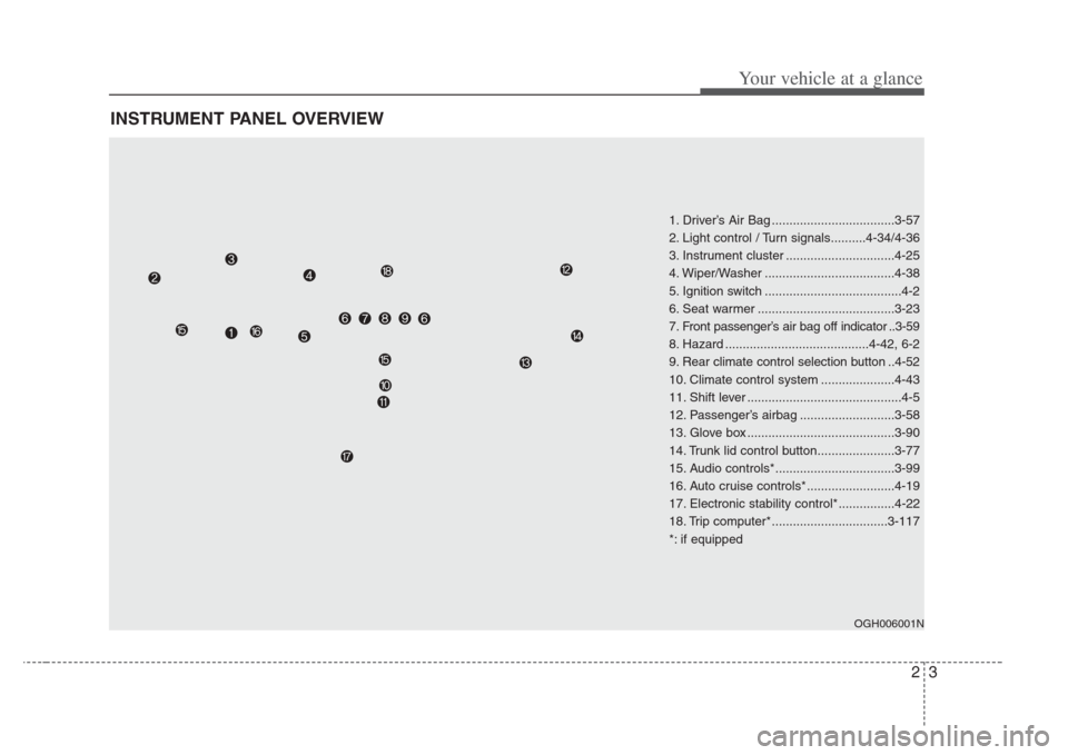
INSTRUMENT PANEL OVERVIEW
1. Driver’s Air Bag ...................................3-57
2. Light control / Turn signals..........4-34/4-36
3. Instrument cluster ...............................4-25
4. Wiper/Washer .....................................4-38
5. Ignition switch .......................................4-2
6. Seat warmer .......................................3-23
7. Front passenger’s air bag off indicator ..3-59
8. Hazard .........................................4-42, 6-2
9. Rear climate control selection button ..4-52
10. Climate control system .....................4-43
11. Shift lever ............................................4-5
12. Passenger’s airbag ...........................3-58
13. Glove box ..........................................3-90
14. Trunk lid control button......................3-77
15. Audio controls*..................................3-99
16. Auto cruise controls* .........................4-19
17. Electronic stability control*................4-22
18. Trip computer* .................................3-117
*: if equipped
OGH006001N
Page 17 of 283

37
Knowing your vehicle
Your vehicle is equipped with an elec-
tronic engine immobilizer system to
reduce the risk of unauthorized vehicle
use.
The immobilizer system is comprised of
a small transponder in the ignition key
and electronic devices inside the vehicle.
With the immobilizer system, whenever
you insert your ignition key into the igni-
tion switch and turn it to ON, it checks
and determines whether the ignition key
is valid or not.
If the key is determined to be valid, the
engine will start.
If the key is determined to be invalid, the
engine will not start.
To deactivate the immobilizer sys-
tem:
Insert the ignition key into the key cylin-
der and turn it to the ON position.
To activate the immobilizer sys-
tem:
Turn the ignition key to the OFF position.
The immobilizer system activates auto-
matically. Without a valid ignition key for
your vehicle, the engine will not start.
✽ NOTICE
When starting the engine, do not use the
key with other immobilizer keys near it.
Otherwise the engine may not start or
may stop soon after it starts. Keep each
keys separate.
Limp home (override) procedure
When you turn the ignition key to the ON
position, if the IMMO indicator remains
on continuously after blinking 6 times,
your transponder equipped in the ignition
key is out of order. You cannot start the
engine without the lime home procedure.
To start the engine, you have to input
your password by using the ignition
switch.
The following procedure is how to input
your password of “2345” as an example.
1. Turn the ignition key to the ON posi-
tion. The IMMO indicator ( ) will
blink 6 times and remain on indicating
the beginning of the limp home proce-
dure.
2. Turn the ignition key to the ACC posi- tion.
IMMOBILIZER SYSTEM (IF EQUIPPED)
CAUTION
Do not put metal accessories nearthe key or ignition key.
The engine may not start for the
metal accessories may interrupt the transponder signal from normally
transmitting
WARNING
In order to prevent theft of your
vehicle, do not leave spare keys
anywhere in your vehicle. Your
Immobilizer pass word is a cus -
tomer unique pass word and should
be kept confidential. Do not leave
this number anywhere in your vehi-
cle.
Page 81 of 283

371
Knowing your vehicle
How does the air bag system
operate
• Air bag only operates when the ignition
switch is turned to the ON or START
positions.
• Air bags inflate instantly in the event of serious frontal or side collision (if
equipped with side air bag or curtain
air bag) in order to help protect the
occupants from serious physical injury.
• There is no single speed at which the air bags will inflate.
Generally, air bags are designed to
inflate by the severity of a collision and
its direction. These two factors deter-
mine whether the sensors send out an
electronic deployment/inflation signal. • Air bag deployment depends on a
number of factors including vehicle
speed, angles of impact and the densi-
ty and stiffness of the vehicles or
objects which your vehicle hits in the
collision. However, factors are not limit-
ed to those mentioned above.
• The front air bags will completely inflate and deflate in an instant.
It is virtually impossible for you to see
the air bags inflate during an accident.
It is much more likely that you will sim-
ply see the deflated air bags hanging
out of their storage compartments after
the collision. • In order to help provide protection in a
severe collision, the air bags must
inflate rapidly. The speed of air bag
inflation is a consequence of the
extremely short time in which a collision
occurs and the need to get the air bag
between the occupant and the vehicle
structures before the occupant impacts
those structures. This speed of inflation
reduces the risk of serious or life-
threatening injuries in a severe collision
and is thus a necessary part of air bag
design.
However, air bag inflation can also
cause injuries which normally can
include facial abrasions, bruises and
broken bones, and sometimes more
serious injuries because that inflation
speed also causes the air bags to
expand with a great deal force.
• There are even circums tances
under which contact with the steer-
ing wheel air bag can cause fatal
injuries,e specially if the occupant
is positioned excessively close to
the steering wheel.
Page 108 of 283

Knowing your vehicle
983
Resetting the sunroof
Whenever the vehicle battery is discon-
nected or discharged, or you use the
emergency handle to operate the sun-
roof, you have to reset your sunroof sys-
tem as follows:
1. Turn the ignition key to the ON posi-tion.
2. According to the position of the sun- roof, do as follows.
1) in case that the sunroof has closedcompletely or been tilted
: Press the TILT UP button for 1 second.
2) in case that the sunroof has slide- opened
: Press and hold the CLOSE button for more than 5 seconds until the
sunroof has closed completely.
And then press the TILT UP but-
ton for 1 second
3. Then, release it.
4. Press and hold the TILT UP button once again until the sunroof has
returned to the original position of
TILT UP after it is raised a little higher
than the maximum TILT UP position.
When this is complete, the sunroof sys-
tem is reset.
Glass antenna (if equipped)
When the radio power switch is turned on
while the ignition key is in either the “ON”
or “ACC” position, your car will receive
both AM and FM broadcast signals
through the antenna in the rear window
glass.
ANTENNA
OGH036399N
CAUTION
• Do not clean the in side of the rear
window gla ss with a cleaner or
s craper to remove the foreign
deposits a s this may cause dam-
age to the antenna element s.
• Avoid adding metallic coating such as Ni, Cd, and so on. Thesecan disturb receiving AM and FMbroadcast signals.
Page 156 of 283

425
Driving your vehicle
INSTRUMENT CLUSTER
OGH027034C
1. Tachometer
2. Turn signal indicators
3. Speedometer
4. Engine temperature gauge
5. Warning and indicator lights
6. Odometer / Tripmeter
7. Shift position indicator
8. Fuel gauge
Page 162 of 283

431
Driving your vehicle
Trunk lid open
warning
This warning light activates when the
trunk is not closed securely.
Low fuel level
warning
This warning light indicates the fuel tank
is nearly empty. The warning light will
come on when the fuel level has dropped
to about 9 liters. Refuel as soon as pos-
sible.
Door open
display
This warning light illuminates when a
door is not closed securely with the igni-
tion in any position. And the door open
display will illuminate the corresponding
position light which door is not closed
securely.
Immobilizer indicator
(if equipped)
This light illuminates when the immobiliz-
er key is inserted and turned to the ON
position to start the engine.
If this light turns off or blinks when the
ignition switch is in the ON position
before starting the engine, have the sys-
tem checked by an authorized Kia
Dealer.
Headlight high beam
indicator
This indicator illuminates when the head-
lights are on and in the high beam posi-
tion or when the turn signal lever is pulled
into the Flash-to-Pass position.
Malfunction indicator
(if equipped)
This indicator light is part of the Engine
Control System which monitors various
emission control system components. If
this light illuminates while driving, it indi-
cates that a potential problem has been
detected somewhere in the emission
control system.
Generally, your vehicle will continue to be
drivable and will not need towing, but
have the system checked by an
Authorized Kia Dealer as soon as possi-
ble.
✽NOTICE
A loose fuel filler cap may cause the On
Board Diagnostic System Malfunction
Indicator Light ( ) in the instrument
panel to illuminate unnecessarily.
Always make sure that the fuel filler cap
is tight.
TRUNK
OPEN!
LOW
FUEL
DOOR
OPEN!
Page 167 of 283

Driving your vehicle
364
CAUTION
If the automatic headlight aimingsystem does not operate when thevehicle is loaded with pa ssengers
and the front portion of the vehicle is at an elevated angle, or it i s not
adjusting correctly, have the vehicle checked and repaired by an author-ized Kia dealer. Do not attempt toadjus t the headlights manually,
damage to the automatic headlight aiming system could occur.
Turn signals
The ignition switch must be on for the
turn signals to function. To turn on the
turn signals, move the lever up or down.
Green arrow indicators on the instrument
panel indicate which turn signal is oper-
ating. They will self-cancel after a turn is
completed. If the indicator continues to
flash after a turn, manually return the
lever to the OFF position.
Lane change signals
To signal a lane change, move the turn
signal lever slightly and hold it in position.
The lever will return to the OFF position
when released.
If an indicator stays on and does not
flash or if it flashes abnormally, one of the
turn signal bulbs may be burned out and
will require replacement.
✽
NOTICE
If an indicator flash is abnormally quick
or slow, bulb may be burned out or have
a poor electrical connection in the cir-
cuit.
Automatic headlight aiming
(if equipped)
To provide better driver visibility and
reduce eye fatigue, the headlight aiming
(direction) is automatically controlled
depending on vehicle load and vehicle
angle (when vehicle is loaded with pas-
sengers, cargo or used for towing, the
additional load can alter the headlight
aiming point on the road surface). This
system provides constant automatic
headlight aiming under various vehicle
conditions and angles to ensure the
headlights are always pointed in the right
direction.
2GHN2055
Right turn
Left turn
Left lane
change
Right lane
change
Page 173 of 283

Driving your vehicle
424
✽NOTICE
To prevent damage to the conductors
bonded to the inside surface of the
bottom of the front windshield and the
rear window, never use sharp instru-
ments or window cleaners containing
abrasives to clean the window.
To prevent the battery from being dis- charged, operate the defroster only
while the engine is running.
The front windshield defroster is designed to defrost wiper blades. If
you want to defrost and defog the
front windshield, refer to “Windshield
Defrosting and Defogging” in this sec-
tion.
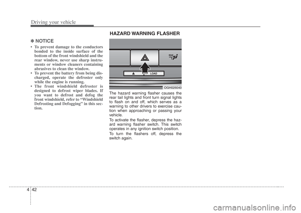
The hazard warning flasher causes the
rear tail lights and front turn signal lights
to flash on and off, which serves as a
warning to other drivers to exercise cau-
tion when approaching or passing your
vehicle.
To activate the flasher, depress the haz-
ard warning flasher switch. This switch
operates in any ignition switch position.
To turn the flashers off, depress the
switch again.
OGH026040
HAZARD WARNING FLASHER