Page 25 of 438

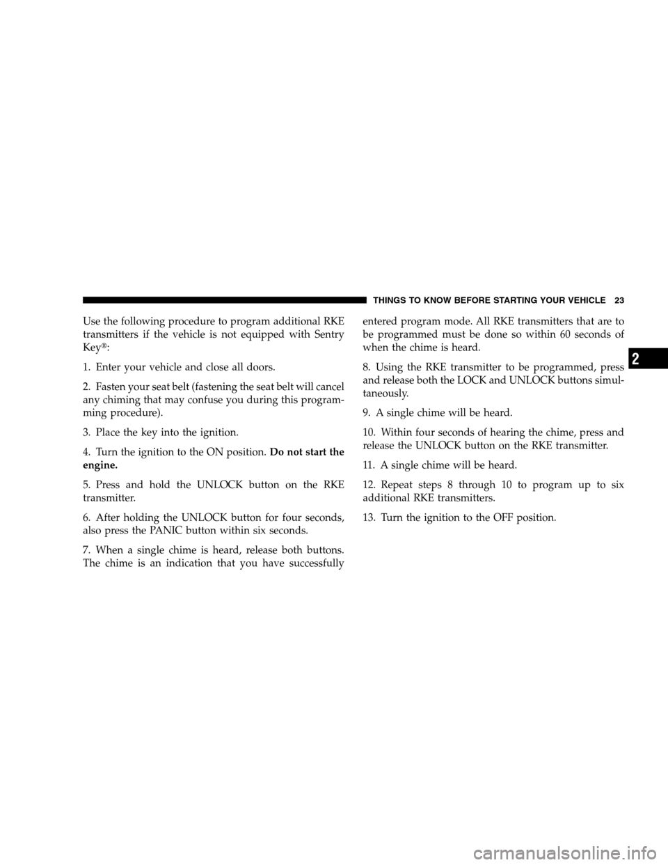
Use the following procedure to program additional RKE
transmitters if the vehicle is not equipped with Sentry
Key�:
1. Enter your vehicle and close all doors.
2. Fasten your seat belt (fastening the seat belt will cancel
any chiming that may confuse you during this program-
ming procedure).
3. Place the key into the ignition.
4. Turn the ignition to the ON position.Do not start the
engine.
5. Press and hold the UNLOCK button on the RKE
transmitter.
6. After holding the UNLOCK button for four seconds,
also press the PANIC button within six seconds.
7. When a single chime is heard, release both buttons.
The chime is an indication that you have successfullyentered program mode. All RKE transmitters that are to
be programmed must be done so within 60 seconds of
when the chime is heard.
8. Using the RKE transmitter to be programmed, press
and release both the LOCK and UNLOCK buttons simul-
taneously.
9. A single chime will be heard.
10. Within four seconds of hearing the chime, press and
release the UNLOCK button on the RKE transmitter.
11. A single chime will be heard.
12. Repeat steps 8 through 10 to program up to six
additional RKE transmitters.
13. Turn the ignition to the OFF position.
THINGS TO KNOW BEFORE STARTING YOUR VEHICLE 23
2
Page 126 of 438
show proper operation of the front and rear turn signal
lights. You can signal a lane change by moving the lever
partially up or down without moving beyond the detent.
If either light remains on and does not flash, or there is a
very fast flash rate, check for a defective outside light
bulb. If an indicator fails to light when the lever is
moved, it would suggest that the fuse or indicator bulb is
defective.Highbeam/Lowbeam Select Switch
Push the Multifunction Control Lever away from you to
switch the headlights to HIGH beam. Pull the Multifunc-
tion Control Lever toward you, to switch the headlights
back to LOW beam.
High Beam Control
124 UNDERSTANDING THE FEATURES OF YOUR VEHICLE
Page 348 of 438

▫Front Suspension Ball Joints..............362
▫Body Lubrication.....................363
▫Windshield Wiper Blades................363
▫Windshield Washer Fluid Reservoir........364
▫Exhaust System......................364
▫Cooling System.......................365
▫Hoses And Vacuum/Vapor Harnesses.......370
▫Fuel System Connections................370
▫Brake System........................371
▫Automatic Transaxle (CVT)..............373
▫Manual Transaxle.....................374
▫Rear Drive Assembly (RDA) – AWD/4WD
Models Only........................375▫Power Transfer Unit (PTU) – AWD/4WD
Models Only........................375
▫Appearance Care And Protection
From Corrosion......................376
�Fuses/Integrated Power Module (IPM).......382
�Vehicle Storage........................385
�Replacement Bulbs......................385
�Bulb Replacement......................386
▫Headlamps..........................386
▫Fog Lights..........................389
▫Tail Lights, Rear Turn Signals And Backup
Lights — Replacement..................389
▫License Lights........................391
▫Center High-Mounted Stoplight...........392
346 MAINTAINING YOUR VEHICLE
Page 384 of 438
FUSES/INTEGRATED POWER MODULE (IPM)
An Integrated Power Module (IPM) is located in the
engine compartment near the air cleaner assembly. This
center contains cartridge fuses and mini-fuses. A label
that identifies each component may be printed on the
inside of the cover. Refer to “Engine Compartment” in
this section of the Owner’s Manual for the underhood
location of the IPM.
Cavity Cartridge
FuseMini-
FuseDescription
1 Empty Empty
2 15 Amp
Lt BlueAWD/4WD ECU
Feed
3 10 Amp
RedCHMSL Brake Switch
Feed
4 10 Amp
RedIgnition Switch Feed
5 20 Amp
YellowTrailer Tow
Cavity Cartridge
FuseMini-
FuseDescription
6 10 Amp
RedIOD Sw/Pwr Mir/
Ocm Steering Cntrl
Sdar/Hands-Free
Phone
7 30 Amp
GreenIOD Sense1
8 30 Amp
GreenIOD Sense2
9 40 Amp
GreenPower Seats
10 20 Amp
YellowCCN Power Locks
11 15 Amp
Lt BluePower Outlet
12 20 Amp
YellowIgn Run/Acc Inverter
382 MAINTAINING YOUR VEHICLE
Page 385 of 438
Cavity Cartridge
FuseMini-
FuseDescription
13 20 Amp
YellowPwr run/Acc Outlet
RR
14 10 Amp
RedIOD CCN/ Interior
Lighting
15 40 Amp
GreenRAD Fan Relay Bat-
tery Feed
16 15 Amp
Lt BlueIGN Run/Acc Cigar
Ltr/Sunroof
17 10 Amp
RedIOD Feed Mod-Wcm
18 40 Amp
GreenASD Relay Contact
PWR Feed
19 20 Amp
YellowPWR Amp 1 & Amp
2 Feed
20 15 Amp
Lt BlueIOD Feed RadioCavity Cartridge
FuseMini-
FuseDescription
21 10 Amp
RedIOD Feed Intrus
Mod/Siren
22 10 Amp
RedIGN RUN Heat/AC/
Compass Sensor
23 15 Amp
Lt BlueENG ASD Relay Feed
3
24 15 Amp
Lt BluePower Sunroof Feed
25 10 Amp
RedHeated Mirror
26 15 Amp
Lt BlueENG ASD Relay Feed
2
27 10 Amp
RedIGN RUN Only ORC
Feed
28 10 Amp
RedIGN RUN ORC/OCM
Feed
MAINTAINING YOUR VEHICLE 383
7
Page 386 of 438
Cavity Cartridge
FuseMini-
FuseDescription
29 Hot Car (No Fuse Re-
quired)
30 20 Amp
YellowHeated Seats
31 10 Amp
RedHeadlamp Washer
Relay Control
32 30 Amp
PinkENG ASD Control
Feed 1
33 10 Amp
RedABS MOD/J1962
Conn/PCMCavity Cartridge
FuseMini-
FuseDescription
34 30 Amp
PinkABS Valve Feed
35 40 Amp
GreenABS Pump Feed
36 30 Amp
PinkHeadlamp/Washer
Control/Smart Glass
37 25 Amp
Natural110 Inverter
384 MAINTAINING YOUR VEHICLE
Page 387 of 438

CAUTION!
•When installing the IPM cover, it is important to
ensure the cover is properly positioned and fully
latched. Failure to do so may allow water to get
into the IPM, and possibly result in an electrical
system failure.
•When replacing a blown fuse, it is important to
use only a fuse having the correct amperage rating.
The use of a fuse with a rating other than indicated
may result in a dangerous electrical system over-
load. If a properly rated fuse continues to blow, it
indicates a problem in the circuit that must be
corrected.
VEHICLE STORAGE
If you will not be using your vehicle for more than 21
days, you may want to take steps to preserve your
battery.
•Disengage the mini-fuse in the Power Distribution
Center labeled IOD (Ignition Off-Draw).
•Disconnect the negative cable from the battery.
REPLACEMENT BULBS
All the inside bulbs are brass or glass wedge base.
Aluminum base bulbs are not approved and should not
be used for replacement.
LIGHT BULBS — Interior Bulb Number
Front Header Lamp......................T578
Center Dome Lamp......................T578
Rear Cargo/Flashlight.................8–A35LF
MAINTAINING YOUR VEHICLE 385
7
Page 425 of 438

Fluid, Brake........................... 397
Fluid Capacities......................... 395
Fluid Leaks............................. 71
Fluid Level Checks
Automatic Transaxle.................... 374
Fluids ................................ 396
Fluids, Lubricants and Genuine Parts.......... 396
Fog Lights.......................123,181,389
Fold Down Speakers..................... 161
Folding Rear Seat........................ 116
Folding Rear Seat (Sedan).................. 116
Four Wheel Drive....................... 251
Systems............................. 251
Four Wheel Drive Operation................ 251
Freeing A Stuck Vehicle................... 342
Fuel.............................. 311,396
Adding............................. 314
Additives............................ 313
Capacity............................ 395CleanAir ............................ 311
Filler Cap (Gas Cap).................... 314
Filter ............................... 358
Gasoline............................. 311
Gauge.............................. 172
Hoses.............................. 370
Light ............................... 173
Octane Rating......................... 311
Requirements......................... 311
System Hoses......................... 370
Tank Capacity........................ 395
Fuel System Caution..................... 317
Fueling ............................... 314
Fuses................................ 382
Garage Door Opener (HomeLink�) ........... 142
Gas Cap (Fuel Filler Cap)............314,316,349
Gasoline, Clean Air...................... 311
Gasoline (Fuel)....................... 311,395
INDEX 423
10