Page 3482 of 4083
![INFINITI QX56 2008 Factory Service Manual SRC-84
< ECU DIAGNOSIS >
DIAGNOSIS SENSOR UNIT
PRE-TEN FRONT RH [OPEN] B1081RH seat belt pre-tensioner circuit is
open. 1. Visually check the wiring harness connection.
2. Replace the harness if it h INFINITI QX56 2008 Factory Service Manual SRC-84
< ECU DIAGNOSIS >
DIAGNOSIS SENSOR UNIT
PRE-TEN FRONT RH [OPEN] B1081RH seat belt pre-tensioner circuit is
open. 1. Visually check the wiring harness connection.
2. Replace the harness if it h](/manual-img/42/57030/w960_57030-3481.png)
SRC-84
< ECU DIAGNOSIS >
DIAGNOSIS SENSOR UNIT
PRE-TEN FRONT RH [OPEN] B1081RH seat belt pre-tensioner circuit is
open. 1. Visually check the wiring harness connection.
2. Replace the harness if it has visible damage.
3. Replace the front RH seat belt pre-tensioner.
4. Replace the air bag diagnosis sensor unit.
5. Replace the related harness.
PRE-TEN FRONT RH
[VB-SHORT] B1082RH seat belt pre-tensioner circuit is
shorted to a power supply circuit.
PRE-TEN FRONT RH [GND-SHORT] B1083
RH seat belt pre-tensioner circuit is
shorted to ground.
PRE-TEN FRONT RH [SHORT] B1084RH seat belt pre-tensioner circuits are
shorted to each other.
PRE-TEN2 FRONT LH [OPEN] B1182LH seat belt buckle pre-tensioner circuit
is open. 1. Visually check the wiring harness connection.
2. Replace the harness if it has visible damage.
3. Replace the front LH seat belt buckle pre-ten-
sioner.
4. Replace the air bag diagnosis sensor unit.
5. Replace the related harness.
PRE-TEN2 FRONT LH
[VB-SHORT] B1183
LH seat belt buckle pre-tensioner circuit
is shorted to a power supply circuit.
PRE-TEN2 FRONT LH [GND-SHORT] B1184LH seat belt buckle pre-tensioner circuit
is shorted to ground.
PRE-TEN2 FRONT LH [SHORT] B1185LH seat belt buckle pre-tensioner cir-
cuits are shorted to each other.
PRE-TEN2 FRONT RH [OPEN] B1177
RH seat belt buckle pre-tensioner circuit
is open. 1. Visually check the wiring harness connection.
2. Replace the harness if it has visible damage.
3. Replace the front RH seat belt buckle pre-ten-
sioner.
4. Replace the air bag diagnosis sensor unit.
5. Replace the related harness.
PRE-TEN2 FRONT RH
[VB-SHORT] B1178RH seat belt buckle pre-tensioner circuit
is shorted to a power supply circuit.
PRE-TEN2 FRONT RH [GND-SHORT] B1179RH seat belt buckle pre-tensioner circuit
is shorted to ground.
PRE-TEN2 FRONT RH [SHORT] B1180
RH seat belt buckle pre-tensioner cir-
cuits are shorted to each other.
CRASH ZONE SEN [UNIT FAIL] B1033 Crash zone sensor has malfunctioned. 1. Visually check the wiring harness connection.
2. Replace the harness if it has visible damage.
3. Replace the crash zone sensor.
4. Replace the air bag diagnosis sensor unit.
5. Replace the related harness.
B1034
CRASH ZONE SEN [COMM FAIL] B1035Crash zone sensor communication er-
ror.
SATELLITE SENS LH [UNIT FAIL] B1118 LH side air bag satellite sensor has mal-
functioned. 1. Visually check the wiring harness connection.
2. Replace the harness if it has visible damage.
3. Replace the LH side air bag satellite sensor.
4. Replace the air bag diagnosis sensor unit.
5. Replace the related harness.
B 111 9
SATELLITE SENS LH [COMM FAIL] B1120LH side air bag satellite sensor commu-
nication error.
SATELLITE SENS RH [UNIT FAIL] B1
113
RH side air bag satellite sensor has mal-
functioned. 1. Visually check the wiring harness connection.
2. Replace the harness if it has visible damage.
3. Replace the RH side air bag satellite sensor.
4. Replace the air bag diagnosis sensor unit.
5. Replace the related harness.
B 111 4
SATELLITE SENS RH [COMM FAIL] B 111 5RH side air bag satellite sensor commu-
nication error.
CONTROL UNIT B1XXX Air bag diagnosis sensor unit is malfunc-
tioning.
1. Visually check the wiring harness connection.
2. Replace the harness if it has visible damage.
3. Replace the air bag diagnosis sensor unit.
4. Replace the related harness.
PASS A/B INDCTR CKT B1023 Front passenger air bag OFF indicator is
malfunctioning.
1. Visually check the wiring harness connection.
2. Replace the harness if it has visible damage.
3. Replace the front passenger air bag OFF in-
dicator.
4. Replace the air bag diagnosis sensor unit.
5. Replace the related harness.
OCCUPANT SENS C/U [UNIT FAIL] B1017 The OCS control unit is malfunctioning. 1. Replace the RH front seat cushion assembly.
Do not disassemble the seat cushion assem-
bly.
B1021
B1020 The OCS control unit is malfunctioning. 1. Replace the harness if it has visible damage.
2. Replace the RH front seat cushion assembly.
Do not disassemble the seat cushion assem-
bly.
3. Replace the RH front seat belt assembly.
CONSULT-III name DTC
DTC detecting condition Repair order
Revision: March 2010 2008 QX56
Page 3483 of 4083

DIAGNOSIS SENSOR UNITSRC-85
< ECU DIAGNOSIS >
C
DE
F
G
I
J
K L
M A
B
SRC
N
O P
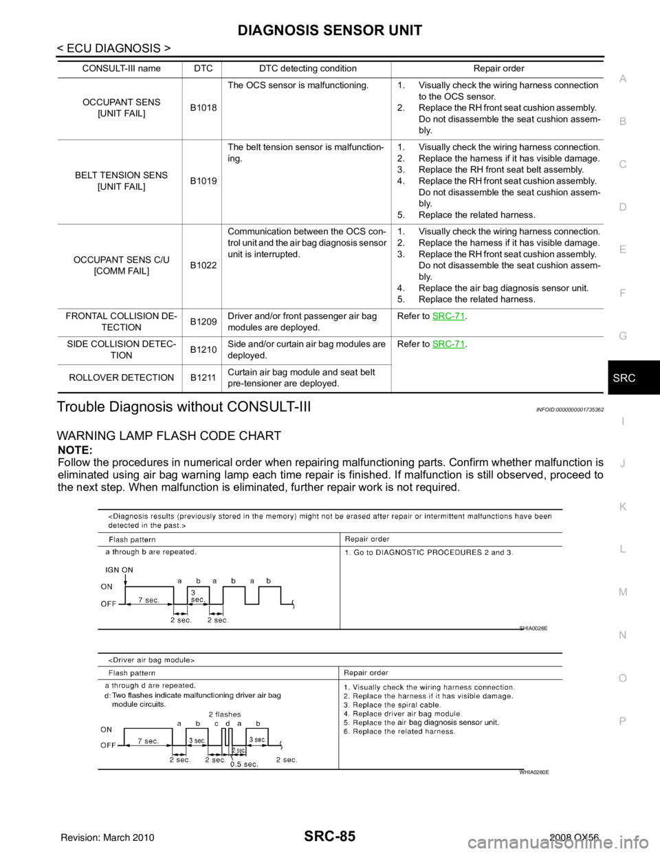
Trouble Diagnosis without CONSULT-IIIINFOID:0000000001735362
WARNING LAMP FLASH CODE CHART
NOTE:
Follow the procedures in numerical order when repairi ng malfunctioning parts. Confirm whether malfunction is
eliminated using air bag warning lamp each time repair is finished. If malfunction is still observed, proceed to
the next step. When malfunction is eliminated, fu rther repair work is not required.
OCCUPANT SENS
[UNIT FAIL] B1018The OCS sensor is malfunctioning. 1. Visually check the wiring harness connection
to the OCS sensor.
2. Replace the RH front seat cushion assembly. Do not disassemble the seat cushion assem-
bly.
BELT TENSION SENS [UNIT FAIL] B1019The belt tension sensor is malfunction-
ing.
1. Visually check the wiring harness connection.
2. Replace the harness if it has visible damage.
3. Replace the RH front seat belt assembly.
4. Replace the RH front seat cushion assembly.
Do not disassemble the seat cushion assem-
bly.
5. Replace the related harness.
OCCUPANT SENS C/U [COMM FAIL] B1022Communication between the OCS con-
trol unit and the air bag diagnosis sensor
unit is interrupted.
1. Visually check the wiring harness connection.
2. Replace the harness if it has visible damage.
3. Replace the RH front seat cushion assembly.
Do not disassemble the seat cushion assem-
bly.
4. Replace the air bag diagnosis sensor unit.
5. Replace the related harness.
FRONTAL COLLISION DE- TECTION B1209Driver and/or front passenger air bag
modules are deployed. Refer to SRC-71
.
SIDE COLLISION DETEC- TION B1210
Side and/or curtain air bag modules are
deployed. Refer to SRC-71
.
ROLLOVER DETECTION B1211 Curtain air bag module and seat belt
pre-tensioner are deployed.
CONSULT-III name DTC
DTC detecting condition Repair order
SHIA0026E
WHIA0260E
Revision: March 2010 2008 QX56
Page 3484 of 4083
SRC-86
< ECU DIAGNOSIS >
DIAGNOSIS SENSOR UNIT
WHIA0198E
WHIA0261E
WHIA0200E
WHIA0262E
WHIA0263E
Revision: March 20102008 QX56
Page 3485 of 4083
DIAGNOSIS SENSOR UNITSRC-87
< ECU DIAGNOSIS >
C
DE
F
G
I
J
K L
M A
B
SRC
N
O P
WHIA0250E
WHIA0251E
WHIA0203E
WHIA0204E
WHIA0264E
Revision: March 2010 2008 QX56
Page 3486 of 4083
SRC-88
< ECU DIAGNOSIS >
DIAGNOSIS SENSOR UNIT
WHIA0265E
WHIA0255E
WHIA0253E
WHIA0254E
WHIA0252E
Revision: March 20102008 QX56
Page 3487 of 4083
DIAGNOSIS SENSOR UNITSRC-89
< ECU DIAGNOSIS >
C
DE
F
G
I
J
K L
M A
B
SRC
N
O P
WHIA0211E
WHIA0212E
Revision: March 2010 2008 QX56
Page 3514 of 4083

POWER STEERING GEAR AND LINKAGEST-23
< REMOVAL AND INSTALLATION >
C
DE
F
H I
J
K L
M A
B
ST
N
O P
POWER STEERING GEAR AND LINKAGE
Removal and InstallationINFOID:0000000004920101
CAUTION:
Spiral cable may snap due to steering operation if steering column is separated from steering gear
assembly. Therefore secure steer ing wheel to avoid turning.
REMOVAL
1. Turn wheels to the straight-ahead position.
2. Remove tires from vehicle using power tool.
3. Remove undercover using power tool.
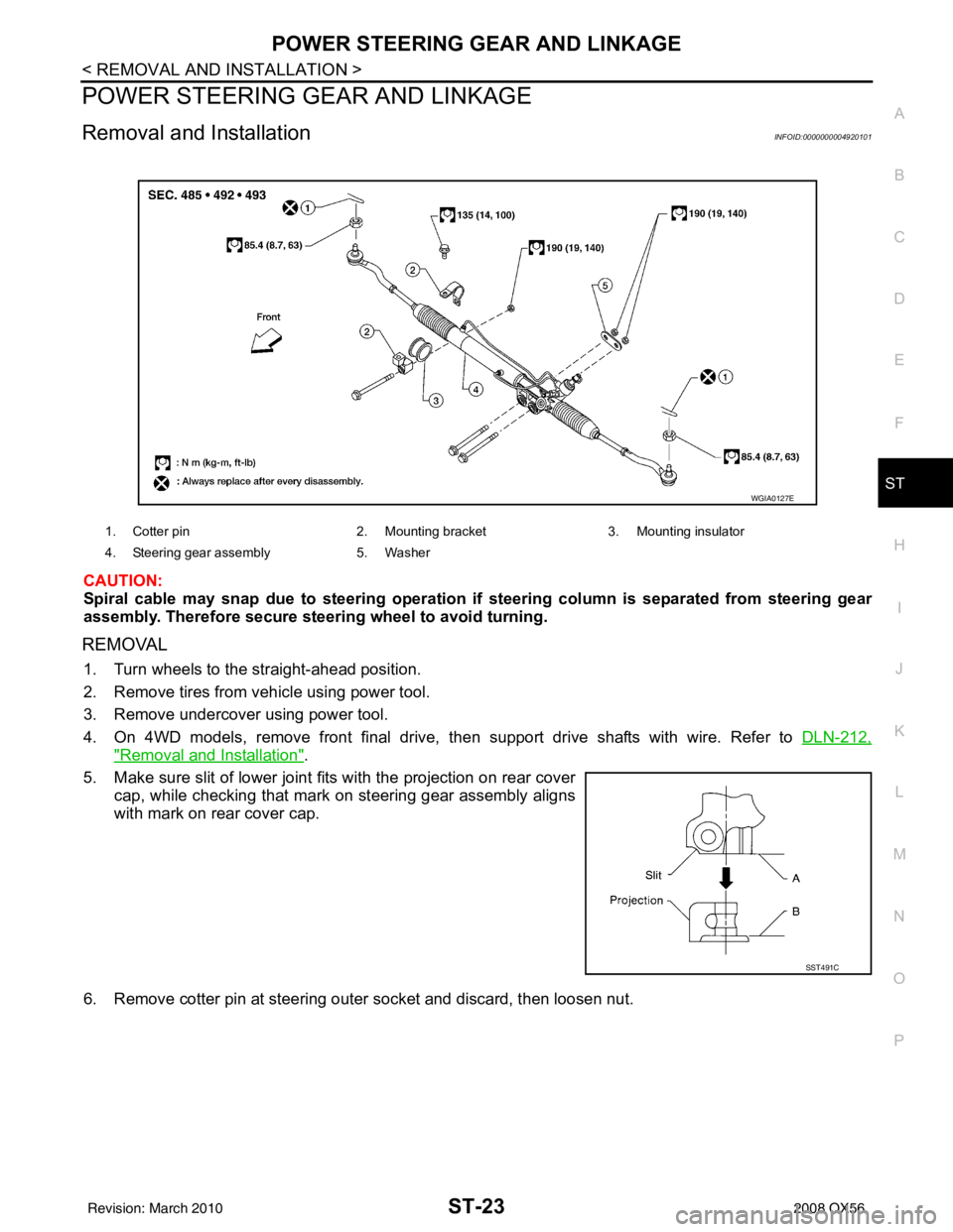
4. On 4WD models, remove front final drive, then support drive shafts with wire. Refer to DLN-212,
"Removal and Installation".
5. Make sure slit of lower joint fits with the projection on rear cover cap, while checking that mark on steering gear assembly aligns
with mark on rear cover cap.
6. Remove cotter pin at steering outer socket and discard, then loosen nut.
1. Cotter pin 2. Mounting bracket 3. Mounting insulator
4. Steering gear assembly 5. Washer
WGIA0127E
SST491C
Revision: March 2010 2008 QX56
Page 3522 of 4083

POWER STEERING GEAR AND LINKAGEST-31
< DISASSEMBLY AND ASSEMBLY >
C
DE
F
H I
J
K L
M A
B
ST
N
O P
POWER STEERING GEAR AND LINKAGE
Disassembly and AssemblyINFOID:0000000004920105
CAUTION:
• Secure steering gear assembly with a vise, using copper plates or something similar to prevent it
from being damaged. Do not grip cylinder with a vise.
• Before performing disassembly, clean steering gear assembly with kerosene. Be careful not to bring
any kerosene into contact with the di scharge and return port connectors.
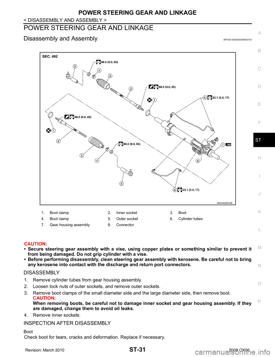
DISASSEMBLY
1. Remove cylinder tubes from gear housing assembly.
2. Loosen lock nuts of outer sockets, and remove outer sockets.
3. Remove boot clamps of the small diameter si de and the large diameter side, then remove boot.
CAUTION:
When removing boots, be careful not to damage inner socket and gear housing assembly. If they
are damaged, change th em to avoid oil leaks.
4. Remove inner sockets.
INSPECTION AFTER DISASSEMBLY
Boot
Check boot for tears, cracks and deformation. Replace if necessary.
1. Boot clamp 2. Inner socket3. Boot
4. Boot clamp 5. Outer socket6. Cylinder tubes
7. Gear housing assembly 8. Connector
AWGIA0087GB
Revision: March 2010 2008 QX56