Page 3014 of 4083

RF-30
< ECU DIAGNOSIS >
SUNROOF SYSTEM
SUNROOF SYSTEM
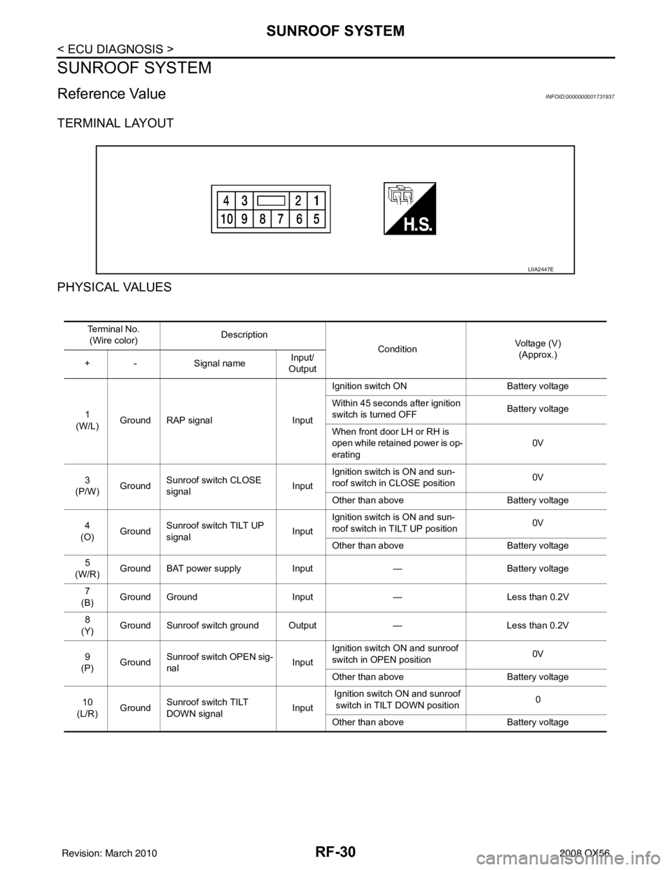
Reference ValueINFOID:0000000001731937
TERMINAL LAYOUT
PHYSICAL VALUES
LIIA2447E
Te r m i n a l N o .(Wire color) Description
ConditionVoltage (V)
(Approx.)
+ - Signal nameInput/
Output
1
(W/L) Ground RAP signal
InputIgnition switch ON
Battery voltage
Within 45 seconds after ignition
switch is turned OFF Battery voltage
When front door LH or RH is
open while retained power is op-
erating 0V
3
(P/W) Ground Sunroof switch CLOSE
signal InputIgnition switch is ON and sun-
roof switch in CLOSE position
0V
Other than above Battery voltage
4
(O) Ground Sunroof switch TILT UP
signal
InputIgnition switch is ON and sun-
roof switch in TILT UP position
0V
Other than above Battery voltage
5
(W/R) Ground BAT power supply
Input— Battery voltage
7
(B) Ground Ground
Input— Less than 0.2V
8
(Y) Ground Sunroof switch ground Output
—Less than 0.2V
9
(P) Ground
Sunroof switch OPEN sig-
nal InputIgnition switch ON and sunroof
switch in OPEN position
0V
Other than above Battery voltage
10
(L/R) Ground Sunroof switch TILT
DOWN signal InputIgnition switch ON and sunroof
switch in TILT DOWN position 0
Other than above Battery voltage
Revision: March 2010 2008 QX56
Page 3015 of 4083
SUNROOF SYSTEMRF-31
< ECU DIAGNOSIS >
C
DE
F
G H
I
J
L
M A
B
RF
N
O P
Wiring DiagramINFOID:0000000001731938
AAKWA0138GB
Revision: March 2010 2008 QX56
Page 3016 of 4083
RF-32
< ECU DIAGNOSIS >
SUNROOF SYSTEM
ALKIA0863GB
Revision: March 20102008 QX56
Page 3017 of 4083
SUNROOF SYSTEMRF-33
< ECU DIAGNOSIS >
C
DE
F
G H
I
J
L
M A
B
RF
N
O P
ALKIA0864GB
Revision: March 2010 2008 QX56
Page 3018 of 4083
RF-34
< ECU DIAGNOSIS >
SUNROOF SYSTEM
AWKIA0104GB
Revision: March 20102008 QX56
Page 3019 of 4083
SUNROOF DOES NOT OPERATE PROPERLYRF-35
< SYMPTOM DIAGNOSIS >
C
DE
F
G H
I
J
L
M A
B
RF
N
O P
SYMPTOM DIAGNOSIS
SUNROOF DOES NOT OPERATE PROPERLY
Diagnosis ProcedureINFOID:0000000001731939
1. CHECK BCM POWER SUPPLY AND GROUND CIRCUIT
Check BCM power supply and ground circuit.
Refer to BCS-32, "
Diagnosis Procedure".
>> GO TO 2
2. CHECK SUNROOF MOTOR ASSEMBLY POWER SUPPLY AND GROUND CIRCUIT
Check sunroof motor assembly power supply and ground circuit.
Refer to RF-12, "
ComponentFunctionCheck".
>> GO TO 3
3. CHECK SUNROOF SWITCH CIRCUIT
Check sunroof switch circuit.
Refer to RF-12, "
Diagnosis Procedure".
Is the inspection result normal?
>> Check intermittent incident. Refer to GI-38, "Intermittent Incident".
Revision: March 2010 2008 QX56
Page 3023 of 4083
SUNROOF DOES NOT OPERATE ANTI-PINCH FUNCTIONRF-39
< SYMPTOM DIAGNOSIS >
C
DE
F
G H
I
J
L
M A
B
RF
N
O P
SUNROOF DOES NOT OPERATE ANTI-PINCH FUNCTION
Diagnosis ProcedureINFOID:0000000001731943
1. PERFORM INITIALIZATION PROCEDURE
Perform initialization procedure.
Refer to RF-5, "
ADDITIONAL SERVICE WHEN REPLACING CO NTROL UNIT : Special Repair Requirement".
Is the inspection result normal?
>> Check intermittent incident. Refer to GI-38, "Intermittent Incident".
Revision: March 2010 2008 QX56
Page 3027 of 4083

SQUEAK AND RATTLE TROUBLE DIAGNOSESRF-43
< SYMPTOM DIAGNOSIS >
C
DE
F
G H
I
J
L
M A
B
RF
N
O P
Most of these incidents can be repaired by adjusting, se curing or insulating the item(s) or component(s) caus-
ing the noise.
SUNROOF/HEADLINING
Noises in the sunroof/headlining area can often be traced to one of the following:
1. Sunroof lid, rail, linkage or seals making a rattle or light knocking noise
2. Sunvisor shaft shaking in the holder
3. Front or rear windshield touching headlining and squeaking
Again, pressing on the components to stop the noise while duplicating the conditions can isolate most of these
incidents. Repairs usually consist of insulating with felt cloth tape.
SEATS
When isolating seat noise it's important to note the position the seat is in and the load placed on the seat when
the noise is present. These conditions should be duplicated when verifying and isolating the cause of the
noise.
Cause of seat noise include:
1. Headrest rods and holder
2. A squeak between the seat pad cushion and frame
3. The rear seatback lock and bracket
These noises can be isolated by moving or pressing on the suspected components while duplicating the con-
ditions under which the noise occurs. Most of thes e incidents can be repaired by repositioning the component
or applying urethane tape to the contact area.
UNDERHOOD
Some interior noise may be caused by components under the hood or on the engine wall. The noise is then
transmitted into the passenger compartment.
Causes of transmitted underhood noise include:
1. Any component mounted to the engine wall
2. Components that pass through the engine wall
3. Engine wall mounts and connectors
4. Loose radiator mounting pins
5. Hood bumpers out of adjustment
6. Hood striker out of adjustment
These noises can be difficult to isolate since they cannot be reached from the interior of the vehicle. The best
method is to secure, move or insulate one component at a time and test drive the vehicle. Also, engine RPM
or load can be changed to isolate the noise. Repairs can usually be made by moving, adjusting, securing, or
insulating the component causing the noise.
Revision: March 2010 2008 QX56