2008 INFINITI QX56 center console
[x] Cancel search: center consolePage 3038 of 4083

RF-54
< ON-VEHICLE REPAIR >
SUNROOF SYSTEM
1. Position glass lid to sunroof assembly.
2. Install the glass lid assembly screws. (First tighten left front bolt, then tighten right rear bolt on glass lid to
prevent lid from moving while tightening other bolts.)
3. Adjust the glass lid assembly. Refer to RF-49, "
Inspection".
4. Install side cover LH and RH.
WIND DEFLECTOR
Removal
1. Open the sunroof.
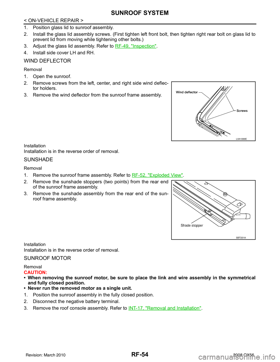
2. Remove screws from the left, center, and right side wind deflec- tor holders.
3. Remove the wind deflector from the sunroof frame assembly.
Installation
Installation is in the reverse order of removal.
SUNSHADE
Removal
1. Remove the sunroof frame assembly. Refer to RF-52, "Exploded View".
2. Remove the sunshade stoppers (two points) from the rear end of the sunroof frame assembly.
3. Remove the sunshade assembly from the rear end of the sun- roof frame assembly.
Installation
Installation is in the reverse order of removal.
SUNROOF MOTOR
Removal
CAUTION:
• When removing the sunroof motor, be sure to place the link and wire assembly in the symmetrical
and fully closed position.
• Never run the removed motor as a single unit.
1. Position the sunroof assembly in the fully closed position.
2. Disconnect the negative battery terminal.
3. Remove the roof console assembly. Refer to INT-17, "
Removal and Installation".
LIIA1099E
SBT251A
Revision: March 2010 2008 QX56
Page 3161 of 4083

SQUEAK AND RATTLE TROUBLE DIAGNOSESSE-39
< SYMPTOM DIAGNOSIS >
C
DE
F
G H
I
K L
M A
B
SE
N
O P
SILICONE GREASE
Used instead of UHMW tape that will be visible or not fit.
Note: Will only last a few months.
SILICONE SPRAY
Use when grease cannot be applied.
DUCT TAPE
Use to eliminate movement.
CONFIRM THE REPAIR
Confirm that the cause of a noise is repaired by test driving the vehicle. Operate the vehicle under the same
conditions as when the noise originally occurred. Refer to the notes on the Diagnostic Worksheet.
Generic Squeak and Rattle TroubleshootingINFOID:0000000001606203
Refer to Table of Contents for specific component removal and installation information.
INSTRUMENT PANEL
Most incidents are caused by contact and movement between:
1. The cluster lid A and instrument panel
2. Acrylic lens and combination meter housing
3. Instrument panel to front pillar garnish
4. Instrument panel to windshield
5. Instrument panel mounting pins
6. Wiring harnesses behind the combination meter
7. A/C defroster duct and duct joint
These incidents can usually be located by tapping or moving the components to duplicate the noise or by
pressing on the components while driving to stop the noi se. Most of these incidents can be repaired by apply-
ing felt cloth tape or silicone spray (in hard to reach areas). Urethane pads can be used to insulate wiring har-
ness.
CAUTION:
Do not use silicone spray to isolate a squeak or ra ttle. If you saturate the area with silicone, you will
not be able to recheck the repair.
CENTER CONSOLE
Components to pay attention to include:
1. Shifter assembly cover to finisher
2. A/C control unit and cluster lid C
3. Wiring harnesses behind audio and A/C control unit
The instrument panel repair and isolation pr ocedures also apply to the center console.
DOORS
Pay attention to the:
1. Finisher and inner panel making a slapping noise
2. Inside handle escutcheon to door finisher
3. Wiring harnesses tapping
4. Door striker out of alignment causing a popping noise on starts and stops
Tapping or moving the components or pressing on them while driving to duplicate the conditions can isolate
many of these incidents. You can usually insulate the ar eas with felt cloth tape or insulator foam blocks from
the NISSAN Squeak and Rattle Kit (J-43980) to repair the noise.
TRUNK
Trunk noises are often caused by a loose jack or loose items put into the trunk by the owner.
In addition look for:
1. Trunk lid bumpers out of adjustment
2. Trunk lid striker out of adjustment
3. The trunk lid torsion bars knocking together
4. A loose license plate or bracket
Revision: March 2010 2008 QX56
Page 3217 of 4083
![INFINITI QX56 2008 Factory Service Manual INTELLIGENT KEY SYSTEM/ENGINE START FUNCTIONSEC-9
< FUNCTION DIAGNOSIS > [WITH INTELLIGENT KEY SYSTEM]
C
D
E
F
G H
I
J
L
M A
B
SEC
N
O P
FUNCTION DIAGNOSIS
INTELLIGENT KEY SYSTEM /ENGINE START FUNCTIO INFINITI QX56 2008 Factory Service Manual INTELLIGENT KEY SYSTEM/ENGINE START FUNCTIONSEC-9
< FUNCTION DIAGNOSIS > [WITH INTELLIGENT KEY SYSTEM]
C
D
E
F
G H
I
J
L
M A
B
SEC
N
O P
FUNCTION DIAGNOSIS
INTELLIGENT KEY SYSTEM /ENGINE START FUNCTIO](/manual-img/42/57030/w960_57030-3216.png)
INTELLIGENT KEY SYSTEM/ENGINE START FUNCTIONSEC-9
< FUNCTION DIAGNOSIS > [WITH INTELLIGENT KEY SYSTEM]
C
D
E
F
G H
I
J
L
M A
B
SEC
N
O P
FUNCTION DIAGNOSIS
INTELLIGENT KEY SYSTEM /ENGINE START FUNCTION
System DiagramINFOID:0000000001539100
System DescriptionINFOID:0000000001539101
INPUT/OUTPUT SIGNAL CHART
Intelligent Key Unit
IPDM E/R
BCM
SYSTEM DESCRIPTION
• The engine start function of Intelligent Key system is a system that makes it possible to start and stop the
engine without using the key. It verifies the electr onic ID using two-way communications when pressing the
ignition knob switch while carrying the Intelligent Key, which operates based on the results of electronic ID
verification for Intelligent Key using two-way communications between the Intelligent Key and the vehicle.
NOTE:
The driver should carry the Intelligent Key at all times.
Switch/Input signal Input signal to
Intelligent Key unit Intelligent Key unit
function Actuator/Output signal
Key switch Mechanical key
(insert/remove)
Engine start function• KEY warning lamp/buzzer
• Steering lock solenoid
• Starter relay requ
est (to IPDM E/R)
• Inside key antenna
(Front and rear center console, over-
head console, luggage compartment)
• Key interlock solenoid
Ignition knob switch
Ignition knob
(push/release)
Steering lock solenoid Steering lock
(lock/unlock)
Inside key antenna
(Front and rear center console, over-
head console, luggage compartment) Intelligent key
(inside antenna detection
area or not.)
Switch/Input signal Input signal to
IPDM E/R IPDM E/R function
Actuator/Output signal
Transmission range switch P, N range Engine start function• Starter relay
• Starter motor
Switch/Input signal Input signal to
BCM BCM function
Actuator/Output signal
Key switch Brake
(press/release)
Engine start function• Inside key antenna
(Front and rear center console, over-
head console, luggage compartment)
ALKIA0925GB
Revision: March 2010 2008 QX56
Page 3219 of 4083
![INFINITI QX56 2008 Factory Service Manual INTELLIGENT KEY SYSTEM/ENGINE START FUNCTIONSEC-11
< FUNCTION DIAGNOSIS > [WITH INTELLIGENT KEY SYSTEM]
C
D
E
F
G H
I
J
L
M A
B
SEC
N
O P
Component Parts LocationINFOID:0000000001539102
ALKIA0958ZZ
1. INFINITI QX56 2008 Factory Service Manual INTELLIGENT KEY SYSTEM/ENGINE START FUNCTIONSEC-11
< FUNCTION DIAGNOSIS > [WITH INTELLIGENT KEY SYSTEM]
C
D
E
F
G H
I
J
L
M A
B
SEC
N
O P
Component Parts LocationINFOID:0000000001539102
ALKIA0958ZZ
1.](/manual-img/42/57030/w960_57030-3218.png)
INTELLIGENT KEY SYSTEM/ENGINE START FUNCTIONSEC-11
< FUNCTION DIAGNOSIS > [WITH INTELLIGENT KEY SYSTEM]
C
D
E
F
G H
I
J
L
M A
B
SEC
N
O P
Component Parts LocationINFOID:0000000001539102
ALKIA0958ZZ
1. BCM M18, M19, M20 (view with instrument panel LH removed) 2. Intelligent Key unit M70
(view with instrument panel LH removed) 3. IPDM E/R
E119, E120, E122, E124
4. ECM E16 5. Key switch and ignition knob switch M12
(view with st eering column removed) 6. Steering lock solenoid M15
7. Remote keyless entry receiver M25 (view with instrume nt panel RH removed) 8. A/T shift selector (detention switch key)
M203
(view with center console removed) 9. Inside key antenna 3 (front of cen-
ter console) M210
(view with center console removed)
Revision: March 2010 2008 QX56
Page 3220 of 4083
![INFINITI QX56 2008 Factory Service Manual SEC-12
< FUNCTION DIAGNOSIS >[WITH INTELLIGENT KEY SYSTEM]
INTELLIGENT KEY SYSTEM/ENGINE START FUNCTION
Component Description
INFOID:0000000001539103
10. Inside key antenna 1 (rear of center con- sole INFINITI QX56 2008 Factory Service Manual SEC-12
< FUNCTION DIAGNOSIS >[WITH INTELLIGENT KEY SYSTEM]
INTELLIGENT KEY SYSTEM/ENGINE START FUNCTION
Component Description
INFOID:0000000001539103
10. Inside key antenna 1 (rear of center con- sole](/manual-img/42/57030/w960_57030-3219.png)
SEC-12
< FUNCTION DIAGNOSIS >[WITH INTELLIGENT KEY SYSTEM]
INTELLIGENT KEY SYSTEM/ENGINE START FUNCTION
Component Description
INFOID:0000000001539103
10. Inside key antenna 1 (rear of center con- sole) M209 11. Inside key antenna 4 (overhead console
area) R210
(view with overhead console removed) 12. Inside key antenna 2 (luggage
compartment) B76
(view with rear carpet removed)
13. Intelligent Key warning buzzer E25 14. Combination meter M23, M24 15. Vehicle security indicator lamp
Item Function
Intelligent Key unit Receives lock/unlock signal from remote keyless entry receiver, and then transmits to BCM.
BCM Verifies the received signal from Intelligent Key, then informs ECM whether to allow engine start.
Remote keyless entry receiver Receives lock/unlock signal from th e Intelligent Key, and then transmits to Intelligent Key unit.
Intelligent Key Transmits button operation to remote keyless entry receiver.
Steering lock solenoid Locks the steering wheel when the ignition key is off and the Intelligent Key is outside the vehicle.
Inside key antenna Detects if Intelligent Key is inside the vehicle.
Intelligent Key warning buzzer Warns the user of the lock/unlock condition and inappropriate operations with the buzzer sound.
A/T shift selector (detention key
switch) Detects whether the shift lever is in park.
Revision: March 2010
2008 QX56
Page 3231 of 4083
![INFINITI QX56 2008 Factory Service Manual DIAGNOSIS SYSTEM (INTELLIGENT KEY UNIT)SEC-23
< FUNCTION DIAGNOSIS > [WITH INTELLIGENT KEY SYSTEM]
C
D
E
F
G H
I
J
L
M A
B
SEC
N
O P
ACTIVE TEST
Monitor Item Condition
PUSH SW Indicates [ON (pressed)/ INFINITI QX56 2008 Factory Service Manual DIAGNOSIS SYSTEM (INTELLIGENT KEY UNIT)SEC-23
< FUNCTION DIAGNOSIS > [WITH INTELLIGENT KEY SYSTEM]
C
D
E
F
G H
I
J
L
M A
B
SEC
N
O P
ACTIVE TEST
Monitor Item Condition
PUSH SW Indicates [ON (pressed)/](/manual-img/42/57030/w960_57030-3230.png)
DIAGNOSIS SYSTEM (INTELLIGENT KEY UNIT)SEC-23
< FUNCTION DIAGNOSIS > [WITH INTELLIGENT KEY SYSTEM]
C
D
E
F
G H
I
J
L
M A
B
SEC
N
O P
ACTIVE TEST
Monitor Item Condition
PUSH SW Indicates [ON (pressed)/OFF (released)] condition of ignition knob switch.
KEY SW Indicates [ON (inserted)/OFF (removed)] cond ition of key switch.
DR REQ SW Indicates [ON (pressed)/OFF (released)] condition of door request swit ch (driver side).
AS REQ SW Indicates [ON (pressed)/OFF (re
leased)] condition of door request switch (passenger
side).
BD/TR REQ SW Indicates [ON (pressed)/OFF (released)] condition of door request switch (back door).
IGN SW Indicates [ON (ON or START position)/OFF (other than ON and START position)] con-
dition of ignition switch ON position.
ACC SW Indicates [ON/OFF] condition of ignition switch ACC position.
STOP LAMP SW Indicates [ON/OFF] condition of stop lamp switch.
DOOR LOCK SIG Indicates [ON/OFF] condition of LOCK signal from Intelligent Key.
DOOR UNLOCK SIG Indicates [ON/OFF] condition of UNLOCK signal from Intelligent Key.
DOOR SW DR Indicates [OPEN/CLOSE] condition of front door switch (driver side) from BCM via CAN
communication.
DOOR SW AS Indicates [OPEN/CLOSE] condition of front door switch (passenger side) from BCM via
CAN communication.
DOOR SW RR Indicates [OPEN/CLOSE] condition of rear door switch (RH) from BCM via CAN com-
munication.
DOOR SW RL Indicates [OPEN/CLOSE] condition of rear door switch (LH) from BCM via CAN com-
munication.
DOOR BK SW Indicates [OPEN/CLOSE] condition of back door switch from BCM via CAN communi-
cation.
VEHICLE SPEED Displays the vehicle speed signal received from combination meter by numerical value
[km/h].
Test item
Description
DOOR LOCK/UNLOCK This test is able to check door lock/unlock operation.
• ALL UNLK: All door lock actuators are unlocked.
• DR UNLK: Door lock actuator
(driver side) is unlocked.
• AS UNLK: Door lock actuator (passenger side) is unlocked.
• BK UNLK: This item is indicated, but inactive.
• LOCK: All door lock actuator is locked.
ANTENNA This test is able to check Intelligent Key antenna operation.
When the following condition are met, hazard warning lamps flash.
• ROOM ANT1: Inside key antenna (console) detects Intelligent Key, when “ROOM
ANT1” is selected.
• ROOM ANT2: Inside key antenna (instrument center/rear seat) detects Intelligent
Key, when “ROOM ANT2”is selected.
• DRIVER ANT: Outside key antenna (driver side) detects Intelligent Key, when “DRIV- ER ANT” is selected.
• ASSIST ANT: Outside key antenna (passenger side) detects Intelligent Key, when “ASSIST ANT” is selected.
• BK DOOR ANT: Outside key antenna (rear bumper) detects Intelligent Key, when “BK
DOOR ANT” is selected.
OUTSIDE BUZZER This test is able to check Intelligent Key warning buzzer operation.
•ON
•OFF
INSIDE BUZZER This test is able to check warning chime in combination meter operation.
• TAKE OUT: Take away
warning chime sounds.
• KNOB: Ignition knob switch warning chime sounds.
• KEY: Key warning chime sounds.
•OFF
Revision: March 2010 2008 QX56
Page 3319 of 4083
![INFINITI QX56 2008 Factory Service Manual INTELLIGENT KEY SYSTEM/ENGINE START FUNCTION SYMPTOMS
SEC-111
< SYMPTOM DIAGNOSIS > [WITH INTELLIGENT KEY SYSTEM]
C
D
E
F
G H
I
J
L
M A
B
SEC
N
O P
SYMPTOM DIAGNOSIS
INTELLIGENT KEY SYSTEM/ENGIN E STA INFINITI QX56 2008 Factory Service Manual INTELLIGENT KEY SYSTEM/ENGINE START FUNCTION SYMPTOMS
SEC-111
< SYMPTOM DIAGNOSIS > [WITH INTELLIGENT KEY SYSTEM]
C
D
E
F
G H
I
J
L
M A
B
SEC
N
O P
SYMPTOM DIAGNOSIS
INTELLIGENT KEY SYSTEM/ENGIN E STA](/manual-img/42/57030/w960_57030-3318.png)
INTELLIGENT KEY SYSTEM/ENGINE START FUNCTION SYMPTOMS
SEC-111
< SYMPTOM DIAGNOSIS > [WITH INTELLIGENT KEY SYSTEM]
C
D
E
F
G H
I
J
L
M A
B
SEC
N
O P
SYMPTOM DIAGNOSIS
INTELLIGENT KEY SYSTEM/ENGIN E START FUNCTION SYMPTOMS
Symptom TableINFOID:0000000001539175
NOTE:
• Before performing the diagnosis in the following table, check “ SEC-3, "
Work Flow"”.
• Check that vehicle is under the condition shown in “Conditions of vehicle” before starting diagnosis, and check each symptom.
• Engine cranking is enabled when the shift lever is in the "Park" position, and in the "Neutral" position only if the brake pedal is depressed.
• If the following symptoms are detec ted, check systems shown in the “Diagnosis/service procedure” column
in this order.
CONDITIONS OF VEHICLE (OPERATING CONDITIONS)
• Engine start function is ON when setting on CONSULT-III.
• Mechanical key is not inserted in key cylinder.
• One or more of Intelligent Keys with registered Intelligent Key ID is in the vehicle.
Symptom Diagnosis/service procedureReference
page
Ignition switch does not turn on with Intelligent Key.
[LCD displays "KEY DETECTED"] 1. Check steering lock solenoid.
DLK-95
2. Replace Intelligent Key unit.SEC-116
Ignition switch does not turn on with Intelligent Key.
[LCD does not display "PUSH" with arrow toward key
cylinder] 1. Check Intelligent Key unit power supply and ground circuit.
DLK-642. Check ignition knob switch.DLK-112
3. Check key switch (BCM input). D L K - 111
4. Check key switch (Intelligent Key unit input).DLK-109
5. Replace Intelligent Key unit.SEC-116
Ignition switch does not turn on with Intelligent Key.
[LCD displays " NO KEY"] 1a. Check inside key antenna 1 (rear of center console).
DLK-56
1b. Check inside key antenna 2 (luggage compartment).DLK-58
1c. Check inside key antenna 3 (front of center console).DLK-60
1d. Check inside key antenna 4 (overhead console area).DLK-64
2. Replace Intelligent Key unit.SEC-116
Ignition switch does not turn on with mechanical key1. Check key switch (BCM input).
D L K - 1112. Check key switch (Intelligent Key unit input).DLK-109
Engine cannot be cranked with transmission in "Park"
or in "Neutral" position with brake pedal depressed.1. Check transmission signal.
TM-43
2. Check stop lamp switch.EXL-81
Revision: March 2010 2008 QX56
Page 3393 of 4083

DIAGNOSIS SENSOR UNITSR-17
< ON-VEHICLE REPAIR >
C
DE
F
G
I
J
K L
M A
B
SR
N
O P
DIAGNOSIS SENSOR UNIT
Removal and InstallationINFOID:0000000001602208
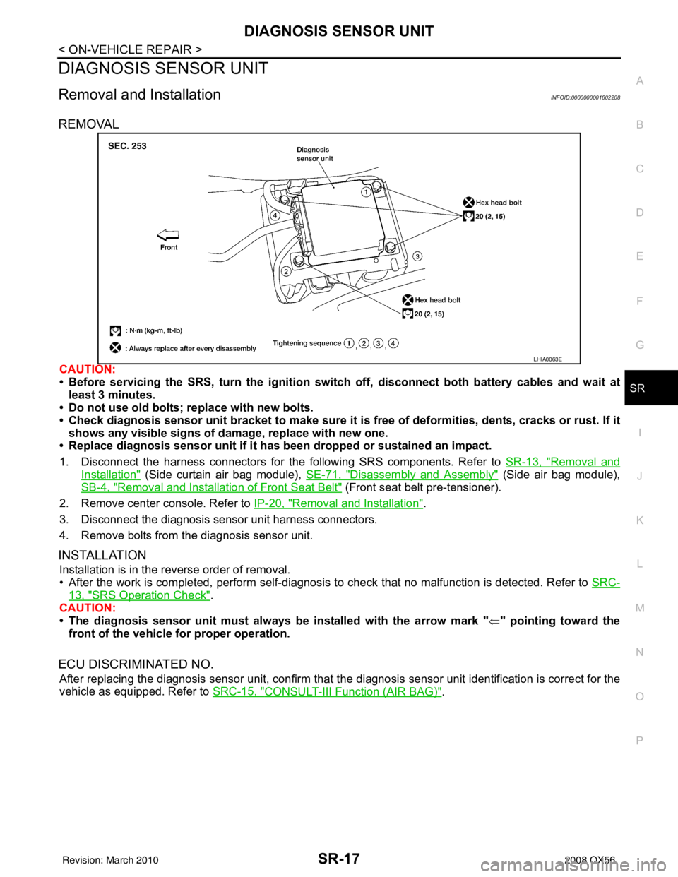
REMOVAL
CAUTION:
• Before servicing the SRS, turn the ignition switch off, disconnect both battery cables and wait at least 3 minutes.
• Do not use old bolts; replace with new bolts.
• Check diagnosis sensor unit bracket to make sure it is free of deformities, dents, cracks or rust. If it
shows any visible signs of damage, replace with new one.
• Replace diagnosis sensor unit if it has been dropped or sustained an impact.
1. Disconnect the harness connectors for the following SRS components. Refer to SR-13, "
Removal and
Installation" (Side curtain air bag module), SE-71, "Disassembly and Assembly" (Side air bag module),
SB-4, "
Removal and Installation of Front Seat Belt" (Front seat belt pre-tensioner).
2. Remove center console. Refer to IP-20, "
Removal and Installation".
3. Disconnect the diagnosis sensor unit harness connectors.
4. Remove bolts from the diagnosis sensor unit.
INSTALLATION
Installation is in the reverse order of removal.
• After the work is completed, perform self-diagnosis to check that no malfunction is detected. Refer to SRC-
13, "SRS Operation Check".
CAUTION:
• The diagnosis sensor unit must always be installed with the arrow mark " ⇐" pointing toward the
front of the vehicle for proper operation.
ECU DISCRIMINATED NO.
After replacing the diagnosis sensor unit, confirm that the diagnosis sensor unit identification is correct for the
vehicle as equipped. Refer to SRC-15, "
CONSULT-III Function (AIR BAG)".
LHIA0063E
Revision: March 2010 2008 QX56