2008 INFINITI QX56 battery volt
[x] Cancel search: battery voltPage 2406 of 4083

IGNITION KEYHOLE ILLUMINATION CONTROL CIRCUIT
INL-23
< COMPONENT DIAGNOSIS >
C
D E
F
G H
I
J
K
M A
B
INL
N
O P
IGNITION KEYHOLE ILLUMI NATION CONTROL CIRCUIT
DescriptionINFOID:0000000001601399
Controls the ignition keyhole illumination (ground side) to turn the ignition keyhole illumination ON and OFF.
Component Function CheckINFOID:0000000001601400
CAUTION:
Before performing the diagnosis, check that the following is normal.
• Battery saver output/power supply circuit
• Ignition keyhole il lumination bulb
1.CHECK IGNITION KEYHOLE ILLUMINATION OPERATION
CONSULT-III
1. Turn the ignition switch ON.
2. Select “IGN ILLUM” of BCM (INT LAMP) active test item.
3. While operating the test item, check that the ignition keyhole illumination turns ON/OFF
Is the inspection result normal?
YES >> Ignition keyhole illumination circuit is normal.
NO >> Refer to INL-23, "
Diagnosis Procedure".
Diagnosis ProcedureINFOID:0000000001601401
1.CHECK IGNITION KEYHOLE OUTPUT
CONSULT-III
1. Turn ignition switch ON.
2. Select “IGN ILLUM” of BCM (INT LAMP) active test item.
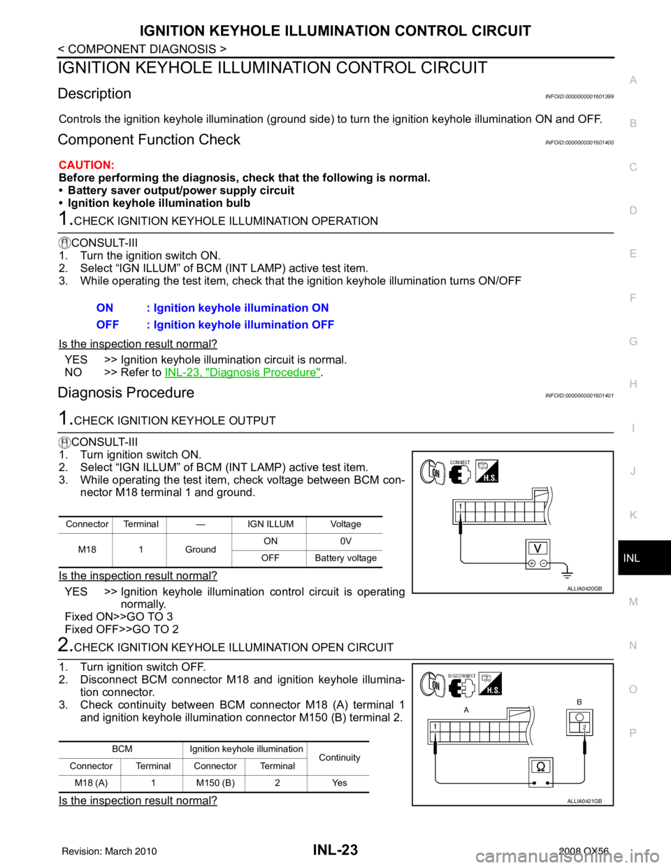
3. While operating the test item, check voltage between BCM con- nector M18 terminal 1 and ground.
Is the inspection result normal?
YES >> Ignition keyhole illumination control circuit is operating normally.
Fixed ON>>GO TO 3
Fixed OFF>>GO TO 2
2.CHECK IGNITION KEYHOLE I LLUMINATION OPEN CIRCUIT
1. Turn ignition switch OFF.
2. Disconnect BCM connector M18 and ignition keyhole illumina- tion connector.
3. Check continuity between BCM connector M18 (A) terminal 1 and ignition keyhole illumination connector M150 (B) terminal 2.
Is the inspection result normal?
ON : Ignition keyhole illumination ON
OFF : Ignition keyhole illumination OFF
Connector Terminal — IGN ILLUM Voltage
M18 1 Ground ON
0V
OFF Battery voltage
ALLIA0420GB
BCM Ignition keyhole illumination
Continuity
Connector Terminal Connector Terminal
M18 (A) 1 M150 (B) 2 Yes
ALLIA0421GB
Revision: March 2010 2008 QX56
Page 2498 of 4083
![INFINITI QX56 2008 Factory Service Manual LAN
PRECAUTIONSLAN-3
< PRECAUTION > [CAN FUNDAMENTAL]
C
D
E
F
G H
I
J
K L
B A
O P
N
PRECAUTION
PRECAUTIONS
Precaution for Trouble DiagnosisINFOID:0000000001374959
CAUTION:
• Never apply 7.0 V or mor INFINITI QX56 2008 Factory Service Manual LAN
PRECAUTIONSLAN-3
< PRECAUTION > [CAN FUNDAMENTAL]
C
D
E
F
G H
I
J
K L
B A
O P
N
PRECAUTION
PRECAUTIONS
Precaution for Trouble DiagnosisINFOID:0000000001374959
CAUTION:
• Never apply 7.0 V or mor](/manual-img/42/57030/w960_57030-2497.png)
LAN
PRECAUTIONSLAN-3
< PRECAUTION > [CAN FUNDAMENTAL]
C
D
E
F
G H
I
J
K L
B A
O P
N
PRECAUTION
PRECAUTIONS
Precaution for Trouble DiagnosisINFOID:0000000001374959
CAUTION:
• Never apply 7.0 V or more to the measurement terminal.
• Use a tester with open terminal voltage of 7.0 V or less.
• Turn the ignition switch OFF and disconnect th
e battery cable from the negative terminal when
checking the harness.
Precaution for Harness RepairINFOID:0000000001374960
• Solder the repaired area and wrap tape around the soldered area. NOTE:
A fray of twisted lines must be within 110 mm (4.33 in).
• Bypass connection is never allowed at the repaired area. NOTE:
Bypass connection may cause CAN communication error. The
spliced wire becomes separated and t he characteristics of twisted
line are lost.
• Replace the applicable harness as an assembly if error is detected on the shield lines of CAN communica- tion line.
SKIB8766E
SKIB8767E
Revision: March 2010 2008 QX56
Page 2502 of 4083
![INFINITI QX56 2008 Factory Service Manual LAN
TROUBLE DIAGNOSISLAN-7
< FUNCTION DIAGNOSIS > [CAN FUNDAMENTAL]
C
D
E
F
G H
I
J
K L
B A
O P
N
TROUBLE DIAGNOSIS
Condition of Error DetectionINFOID:0000000001374966
“U1000” or “U1001” is in INFINITI QX56 2008 Factory Service Manual LAN
TROUBLE DIAGNOSISLAN-7
< FUNCTION DIAGNOSIS > [CAN FUNDAMENTAL]
C
D
E
F
G H
I
J
K L
B A
O P
N
TROUBLE DIAGNOSIS
Condition of Error DetectionINFOID:0000000001374966
“U1000” or “U1001” is in](/manual-img/42/57030/w960_57030-2501.png)
LAN
TROUBLE DIAGNOSISLAN-7
< FUNCTION DIAGNOSIS > [CAN FUNDAMENTAL]
C
D
E
F
G H
I
J
K L
B A
O P
N
TROUBLE DIAGNOSIS
Condition of Error DetectionINFOID:0000000001374966
“U1000” or “U1001” is indicated on SELF-DIAG RESULTS on CONSULT-III if CAN communication signal is
not transmitted or received between units for 2 seconds or more.
CAN COMMUNICATION SYSTEM ERROR
• CAN communication line open (CAN-H, CAN-L, or both)
• CAN communication line short (ground, betw
een CAN communication lines, other harnesses)
• Error of CAN communication control circuit of the unit connected to CAN communication line
WHEN “U1000” OR “U1001” IS INDICATED EV EN THOUGH CAN COMMUNICATION SYSTEM IS
NORMAL
• Removal/installation of parts: Error may be detec ted when removing and installing CAN communication unit
and related parts while turning the ignition switch ON. (A DTC except for CAN communication may be
detected.)
• Fuse blown out (removed): CAN communication of the unit may cease.
• Voltage drop: Error may be detected if voltage drops due to discharged battery when turning the ignition
switch ON (Depending on the control unit which carries out CAN communication).
• Error may be detected if the power supply circuit of the control unit, which carries out CAN communication,
malfunctions (Depending on the control unit which carries out CAN communication).
• Error may be detected if reprogramming is not completed normally.
NOTE:
CAN communication system is normal if “U1000” or “U 1001” is indicated on SELF-DIAG RESULTS of CON-
SULT-III under the above conditions. Erase the memory of the self-diagnosis of each unit.
Symptom When Error Occurs in CAN Communication SystemINFOID:0000000001374967
In CAN communication system, multiple units mutually transmit and receive signals. Each unit cannot transmit
and receive signals if any error occurs on CAN communicati on line. Under this condition, multiple control units
related to the root cause malfunction or go into fail-safe mode.
ERROR EXAMPLE
NOTE:
• Each vehicle differs in symptom of each unit under fail-safe mode and CAN communication line wiring.
• Refer to LAN-36, "
Abbreviation List" for the unit abbreviation.
Example: TCM branch line open circuit
SKIB8738E
Unit name Symptom
ECM Engine torque limiting is affected, and shift harshness increases.
BCM Reverse warning chime does not sound.
Revision: March 2010 2008 QX56
Page 2532 of 4083
![INFINITI QX56 2008 Factory Service Manual LAN
PRECAUTIONSLAN-37
< PRECAUTION > [CAN]
C
D
E
F
G H
I
J
K L
B A
O P
N
PRECAUTION
PRECAUTIONS
Precaution for Supplemental
Restraint System (SRS) "AIR BAG" and "SEAT BELT
PRE-TENSIONER"
INFOID:0000 INFINITI QX56 2008 Factory Service Manual LAN
PRECAUTIONSLAN-37
< PRECAUTION > [CAN]
C
D
E
F
G H
I
J
K L
B A
O P
N
PRECAUTION
PRECAUTIONS
Precaution for Supplemental
Restraint System (SRS) "AIR BAG" and "SEAT BELT
PRE-TENSIONER"
INFOID:0000](/manual-img/42/57030/w960_57030-2531.png)
LAN
PRECAUTIONSLAN-37
< PRECAUTION > [CAN]
C
D
E
F
G H
I
J
K L
B A
O P
N
PRECAUTION
PRECAUTIONS
Precaution for Supplemental
Restraint System (SRS) "AIR BAG" and "SEAT BELT
PRE-TENSIONER"
INFOID:0000000004832404
The Supplemental Restraint System such as “AIR BAG” and “SEAT BELT PRE-TENSIONER”, used along
with a front seat belt, helps to reduce the risk or severi ty of injury to the driver and front passenger for certain
types of collision. This system includes seat belt switch inputs and dual stage front air bag modules. The SRS
system uses the seat belt switches to determine the front air bag deployment, and may only deploy one front
air bag, depending on the severity of a collision and w hether the front occupants are belted or unbelted.
Information necessary to service the system safely is included in the SR and SB section of this Service Man-
ual.
WARNING:
• To avoid rendering the SRS inoper ative, which could increase the risk of personal injury or death in
the event of a collision which would result in air bag inflation, all maintenance must be performed by
an authorized NISSAN/INFINITI dealer.
• Improper maintenance, including in correct removal and installation of the SRS, can lead to personal
injury caused by unintentional act ivation of the system. For removal of Spiral Cable and Air Bag
Module, see the SR section.
• Do not use electrical test equipm ent on any circuit related to the SRS unless instructed to in this
Service Manual. SRS wiring harnesses can be identi fied by yellow and/or orange harnesses or har-
ness connectors.
PRECAUTIONS WHEN USING POWER TOOLS (AIR OR ELECTRIC) AND HAMMERS
WARNING:
• When working near the Airbag Diagnosis Sensor Un it or other Airbag System sensors with the Igni-
tion ON or engine running, DO NOT use air or el ectric power tools or strike near the sensor(s) with a
hammer. Heavy vibration could activate the sensor( s) and deploy the air bag(s), possibly causing
serious injury.
• When using air or electric power tools or hammers, always switch the Ignition OFF, disconnect the battery, and wait at least 3 minutes before performing any service.
Precautions for Trouble DiagnosisINFOID:0000000001282381
CAUTION:
• Never apply 7.0 V or more to the measurement terminal.
• Use a tester with open terminal voltage of 7.0 V or less.
• Turn the ignition switch OFF and disconnect th e battery cable from the negative terminal when
checking the harness.
Precautions for Harness RepairINFOID:0000000001282382
• Solder the repaired area and wrap tape around the soldered area.
NOTE:
A fray of twisted lines must be within 110 mm (4.33 in).
SKIB8766E
Revision: March 2010 2008 QX56
Page 2539 of 4083
![INFINITI QX56 2008 Factory Service Manual LAN-44
< FUNCTION DIAGNOSIS >[CAN]
CAN COMMUNICATION SYSTEM
FUNCTION DIAGNOSIS
CAN COMMUNICATION SYSTEM
CAN System Specification ChartINFOID:0000000001282400
Determine CAN system type from the followi INFINITI QX56 2008 Factory Service Manual LAN-44
< FUNCTION DIAGNOSIS >[CAN]
CAN COMMUNICATION SYSTEM
FUNCTION DIAGNOSIS
CAN COMMUNICATION SYSTEM
CAN System Specification ChartINFOID:0000000001282400
Determine CAN system type from the followi](/manual-img/42/57030/w960_57030-2538.png)
LAN-44
< FUNCTION DIAGNOSIS >[CAN]
CAN COMMUNICATION SYSTEM
FUNCTION DIAGNOSIS
CAN COMMUNICATION SYSTEM
CAN System Specification ChartINFOID:0000000001282400
Determine CAN system type from the following specificat
ion chart. Then choose the correct diagnosis sheet.
NOTE:
Refer to LAN-14, "
Trouble Diagnosis Procedure" for how to use CAN system specification chart.
×: Applicable
VEHICLE EQUIPMENT IDENTIFICATION INFORMATION
NOTE:
Check CAN system type from the vehicle shape and equipment.
CAN Communication Signal ChartINFOID:0000000001282401
Refer to LAN-13, "How to Use CAN Communication Signal Chart" for how to use CAN communication signal
chart.
NOTE:
Refer to LAN-36, "
Abbreviation List" for the abbreviations of the connecting units.
T: Transmit R: Receive
Body type Wagon
Axle 2WD4WD
Engine VK56DE
Transmission A/T
Brake control VDC
ICC system ××
CAN system type 1234
Diagnosis sheet LAN-40
LAN-41LAN-42LAN-43
AWMIA0012GB
Signal name/Connecting unitECM
TCM
LASER ICC
ADP
AV
BCM
HVAC I-KEY M&A
STRG 4WDABS
IPDM-E
Accelerator pedal position signal T RR R R
A/C compressor request signal T R
ASCD CRUISE lamp signal T R
ASCD OD cancel request signal T R
ASCD operation signal T R
ASCD SET lamp signal T R
Battery voltage signal T R
Closed throttle position signal T RR
Cooling fan speed request signal T R
Engine coolant temperature signal T RR
Revision: March 2010 2008 QX56
Page 2650 of 4083

MWI
METER SYSTEMMWI-5
< FUNCTION DIAGNOSIS >
C
DE
F
G H
I
J
K L
M B A
O P
FUNCTION DIAGNOSIS
METER SYSTEM
METER SYSTEM
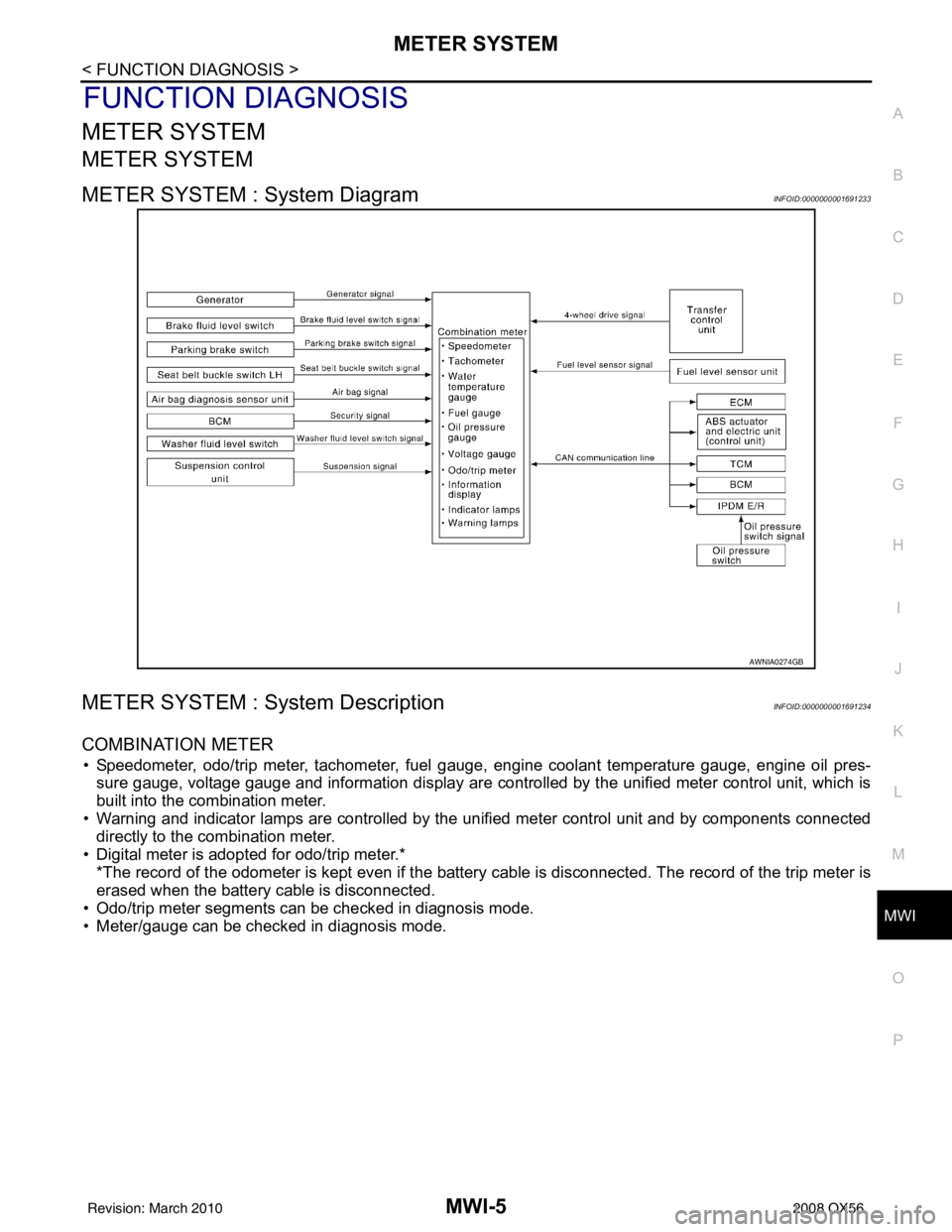
METER SYSTEM : System DiagramINFOID:0000000001691233
METER SYSTEM : System DescriptionINFOID:0000000001691234
COMBINATION METER
• Speedometer, odo/trip meter, tachometer, fuel gauge, engine coolant temperature gauge, engine oil pres-
sure gauge, voltage gauge and information display are controlled by the unified meter control unit, which is
built into the combination meter.
• Warning and indicator lamps are controlled by the unified meter control unit and by components connected directly to the combination meter.
• Digital meter is adopted for odo/trip meter.* *The record of the odometer is kept even if the battery cable is disconnected. The record of the trip meter is
erased when the battery cable is disconnected.
• Odo/trip meter segments can be checked in diagnosis mode.
• Meter/gauge can be checked in diagnosis mode.
AWNIA0274GB
Revision: March 2010 2008 QX56
Page 2652 of 4083

MWI
METER SYSTEMMWI-7
< FUNCTION DIAGNOSIS >
C
DE
F
G H
I
J
K L
M B A
O P
METER SYSTEM : Com ponent Parts LocationINFOID:0000000001691236
METER SYSTEM : Component DescriptionINFOID:0000000001691237
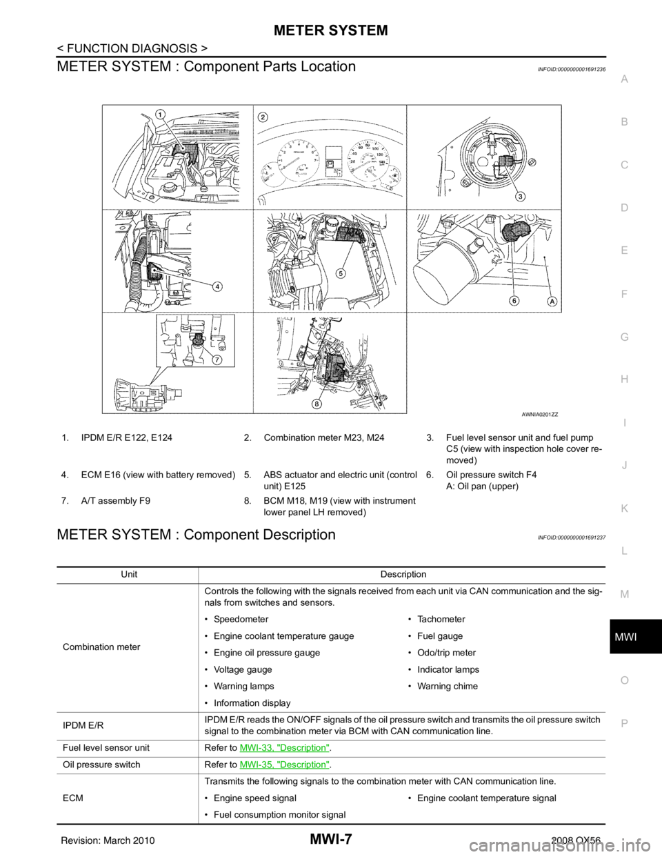
1. IPDM E/R E122, E124 2. Combination meter M23, M24 3. Fuel level sensor unit and fuel pump
C5 (view with inspection hole cover re-
moved)
4. ECM E16 (view with battery removed) 5. ABS actuator and electric unit (control unit) E1256. Oil pressure switch F4
A: Oil pan (upper)
7. A/T assembly F9 8. BCM M18, M19 (view with instrument
lower panel LH removed)
AWNIA0201ZZ
Unit Description
Combination meter Controls the following with the signals received from each unit via CAN communication and the sig-
nals from switches and sensors.
• Speedometer
• Tachometer
• Engine coolant temperature gauge • Fuel gauge
• Engine oil pressure gauge • Odo/trip meter
• Voltage gauge • Indicator lamps
• Warning lamps • Warning chime
• Information display
IPDM E/R IPDM E/R reads the ON/OFF signals of the oil pressure switch and transmits the oil pressure switch
signal to the combination meter via BCM with CAN communication line.
Fuel level sensor unit Refer to MWI-33, "
Description".
Oil pressure switch Refer to MWI-35, "
Description".
ECM Transmits the following signals to the combination meter with CAN communication line.
• Engine speed signal
• Engine coolant temperature signal
• Fuel consumption monitor signal
Revision: March 2010 2008 QX56
Page 2659 of 4083

MWI-14
< FUNCTION DIAGNOSIS >
METER SYSTEM
ENGINE OIL PRESSURE GAUGE : Component Parts Location
INFOID:0000000001696370
ENGINE OIL PRESSURE GAUGE : Component DescriptionINFOID:0000000001691257
VOLTAGE GAUGE
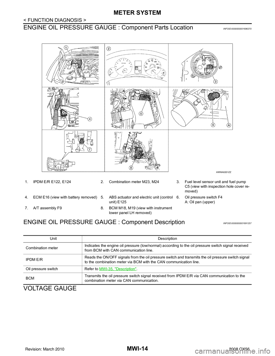
1. IPDM E/R E122, E124 2. Combination meter M23, M24 3. Fuel level sensor unit and fuel pump
C5 (view with inspection hole cover re-
moved)
4. ECM E16 (view with battery removed) 5. ABS actuator and electric unit (control
unit) E125 6. Oil pressure switch F4
A: Oil pan (upper)
7. A/T assembly F9 8. BCM M18, M19 (view with instrument
lower panel LH removed)
AWNIA0201ZZ
Unit Description
Combination meter Indicates the engine oil pressure (low/normal) according to the oil pressure switch signal received
from BCM with CAN
communication line.
IPDM E/R Reads the ON/OFF signals from the oil pressure switch and transmits the oil pressure switch signal
to the combination meter via BCM with the CAN communication line.
Oil pressure switch Refer to MWI-35, "
Description".
BCM Transmits the oil pressure switch signal received from IPDM E/R via CAN communication to the
combination meter via CAN communication.
Revision: March 2010
2008 QX56