2008 INFINITI QX56 seat adjustment
[x] Cancel search: seat adjustmentPage 3037 of 4083
SUNROOF SYSTEMRF-53
< ON-VEHICLE REPAIR >
C
DE
F
G H
I
J
L
M A
B
RF
N
O P
CAUTION:
• Before removal, fully close the glass lid assembly. Then, after removal, do not move the motor
assembly.
• After installing or adjusting the sunroof and glass lid, check gap alignment and sunroof operation to
prevent malfunction.
• Handle glass lid with care so not to cause damage.
Removal and InstallationINFOID:0000000001536769
CAUTION:
• Always work with a helper.
• When taking sunroof unit out, use shop cloths to protect the seats and trim from damage.
• After installing the sunroof unit or glass lid, be sure to check gap adjustment to prevent any mal-
function.
SUNROOF UNIT
NOTE:
• For easier installation, mark each point before removal.
Removal
1. Remove headlining. Refer to INT-17, "Removal and Installation".
2. Remove the sunroof glass lid. Refer to RF-53, "
Removal and Installation".
3. Remove overhead console bracket.
4. Disconnect the drain hoses.
5. Remove front sunroof bolts.
6. Remove rear sunroof bracket bolts.
7. Remove the side bolts and the sunroof unit.
Installation
1. Position the sunroof frame assembly and install the side bolts.
2. Install the rear brackets.
3. Install the front sunroof frame assembly bolts.
4. Connect drain hoses.
5. Install the overhead console bracket.
6. Install the sunroof glass lid. Refer to RF-52, "
Exploded View".
7. Install headlining. Refer to INT-17, "
Removal and Installation".
8. Perform initialization procedure. Refer to RF-5, "
ADDITIONAL SERVICE WHEN REPLACING CONTROL
UNIT : Special Repair Requirement".
GLASS LID
Removal
1. Open sunshade.
2. Ensure glass lid is closed.
3. Remove side cover LH and RH.
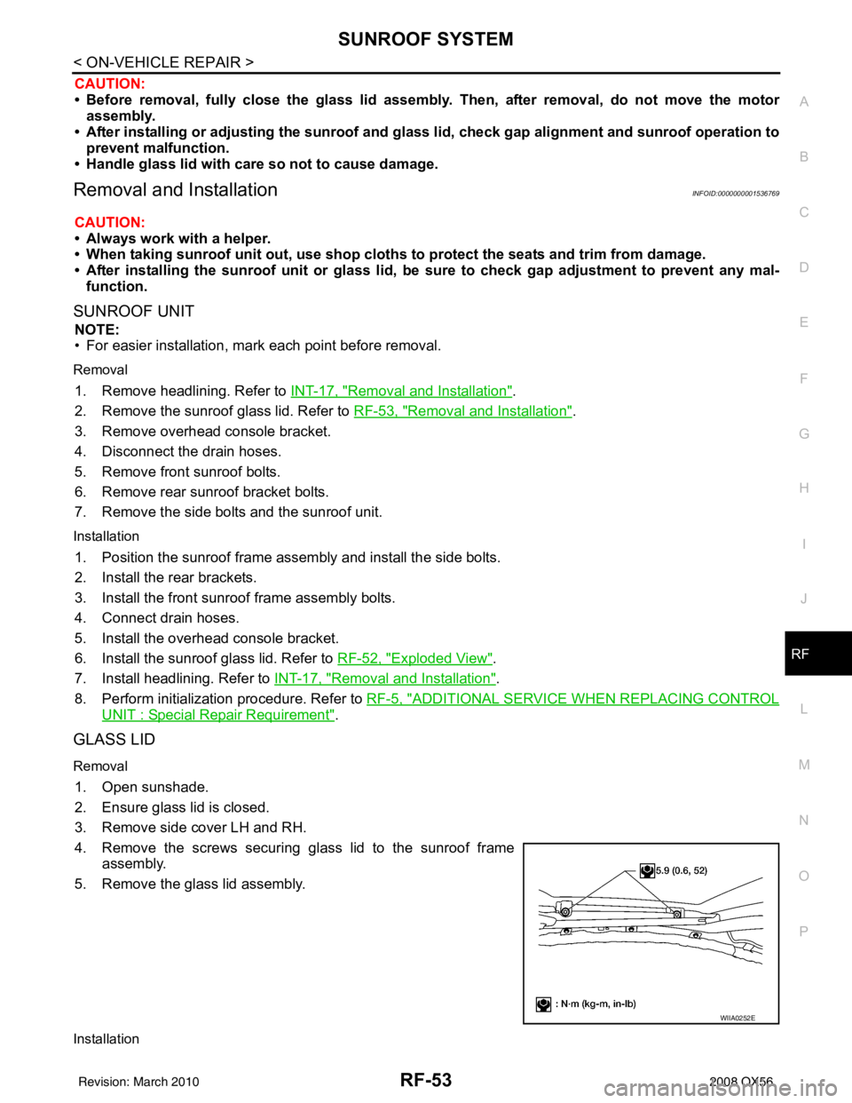
4. Remove the screws securing glass lid to the sunroof frame assembly.
5. Remove the glass lid assembly.
Installation
WIIA0252E
Revision: March 2010 2008 QX56
Page 3123 of 4083
SE-1
BODY INTERIOR
C
DE
F
G H
I
K L
M
SECTION SE
A
B
SE
N
O P
CONTENTS
SEAT
BASIC INSPECTION ....... .............................3
DIAGNOSIS AND REPAIR WORKFLOW ..... .....3
Work Flow ........................................................... ......3
INSPECTION AND ADJUSTMENT .....................5
Preliminary Check ............................................... ......5
FUNCTION DIAGNOSIS ...............................6
THIRD ROW POWER FOLDING SEAT ......... .....6
System Description ............................................. ......6
Component Parts Location ........................................7
Component Description .............................................7
COMPONENT DIAGNOSIS ..........................8
POWER SEAT .....................................................8
Wiring Diagram — Passenger Side — ................ ......8
HEATED SEAT ...................................................12
Description ..............................................................12
Wiring Diagram .......................................................13
THIRD SEAT ......................................................18
Power Supply and Ground Circuit Check for Third
Row Power Folding Seat Control Unit ................. ....
18
Third Row Power Folding Seat Switch ....................19
Third Row Power Folding Seat Motor .....................19
ECU DIAGNOSIS .........................................21
THIRD ROW POWER FOLDING SEAT CON-
TROL UNIT .........................................................
21
Reference Value ................................................. ....21
Wiring Diagram .......................................................23
DTC Index ...............................................................28
Fail Safe ..................................................................29
SYMPTOM DIAGNOSIS ..............................30
THIRD ROW POWER FOLDING SEAT ......... ....30
Symptom Table ................................................... ....30
NONE OF THE THIRD ROW POWER FOLD-
ING SEATS WILL OPERATE WITH ANY
SWITCH. ............................................................
31
None of the Third Row Power Folding Seats Will
Operate With Any Third Row Power Folding Seat
Switch .................................................................. ....
31
ONLY ONE THIRD ROW POWER FOLDING
SEAT WILL OPERATE. ....................................
32
Only One Third Row Power Folding Seat Will Op-
erate .................................................................... ....
32
THIRD ROW POWER FOLDING SEAT WILL
OPERATE IN ONLY ONE DIRECTION. ...........
34
Third Row Power Folding Seat Will Operate in
Only One Direction .............................................. ....
34
THIRD ROW POWER FOLDING SEAT WILL
STOP SHORT OF IT’S FULLY UP OR DOWN
POSITION. .........................................................
35
Third Row Power Folding Seat Stops Short of its
Fully Up or Down Position .......................................
35
THIRD ROW POWER FOLDING SEAT
MAKES EXCESSIVE NOISE WHILE MOV-
ING. ...................................................................
36
Third Row Power Folding Seat Makes Excessive
Noise While Moving ............................................. ....
36
SQUEAK AND RATTLE TROUBLE DIAG-
NOSES ..............................................................
37
Work Flow ................................................................37
Generic Squeak and Rattle Troubleshooting ...........39
Diagnostic Worksheet ..............................................41
PRECAUTION ..............................................43
PRECAUTIONS .................................................43
Precaution for Supplemental Restraint System
(SRS) "AIR BAG" and "SEAT BELT PRE-TEN-
SIONER" ............................................................. ....
43
Revision: March 2010 2008 QX56
Page 3127 of 4083
INSPECTION AND ADJUSTMENTSE-5
< BASIC INSPECTION >
C
DE
F
G H
I
K L
M A
B
SE
N
O P
INSPECTION AND ADJUSTMENT
Preliminary CheckINFOID:0000000001735710
1.FOREIGN OBJECTS
Check the following:
• objects on or behind the seats that could cause binding
• objects under the seats that may be in terfering with the seat’s moving parts
Are there any foreign objects that could be causing interference with the seats?
YES >> Remove objects.
NO >> GO TO 2.
2.WIRING CONNECTIONS
1. Disconnect third row power folding seat c ontrol unit and seat motor harness connectors.
2. Check terminals for damage or loose connections.
3. Reconnect harness connectors.
Are any connectors damaged or loose?
YES >> Repair or replace damaged parts.
NO >> GO TO 3.
3.POWER AND GROUND
Check power supply and ground circuits for third row power folding seat control unit. Refer to SE-18, "
Power
Supply and Ground Circuit Check for Third Row Power Folding Seat Control Unit".
Is the inspection result normal?
YES >> Refer to SE-28, "DTC Index".
NO >> Repair or replace as necessary.
Revision: March 2010 2008 QX56
Page 3162 of 4083
SE-40
< SYMPTOM DIAGNOSIS >
SQUEAK AND RATTLE TROUBLE DIAGNOSES
Most of these incidents can be repaired by adjusting, securing or insulating the item(s) or component(s) caus-
ing the noise.
SUNROOF/HEADLINING
Noises in the sunroof/headlining area c an often be traced to one of the following:
1. Sunroof lid, rail, linkage or seals making a rattle or light knocking noise
2. Sun visor shaft shaking in the holder
3. Front or rear windshield touching headliner and squeaking
Again, pressing on the components to stop the noise while duplicating the conditions can isolate most of these
incidents. Repairs usually consist of insulating with felt cloth tape.
OVERHEAD CONSOLE (FRONT AND REAR)
Overhead console noises are often caused by the c onsole panel clips not being engaged correctly. Most of
these incidents are repaired by pushing up on the c onsole at the clip locations until the clips engage.
In addition look for:
1. Loose harness or harness connectors.
2. Front console map/reading lamp lense loose.
3. Loose screws at console attachment points.
SEATS
When isolating seat noise it's important to note the pos ition the seat is in and the load placed on the seat when
the noise is present. These conditions should be duplicated when verifying and isolating the cause of the
noise.
Cause of seat noise include:
1. Headrest rods and holder
2. A squeak between the seat pad cushion and frame
3. The rear seatback lock and bracket
These noises can be isolated by moving or pressing on the suspected components while duplicating the con-
ditions under which the noise occurs. Most of thes e incidents can be repaired by repositioning the component
or applying urethane tape to the contact area.
UNDERHOOD
Some interior noise may be caused by components under the hood or on the engine wall. The noise is then
transmitted into the passenger compartment.
Causes of transmitted underhood noise include:
1. Any component mounted to the engine wall
2. Components that pass through the engine wall
3. Engine wall mounts and connectors
4. Loose radiator mounting pins
5. Hood bumpers out of adjustment
6. Hood striker out of adjustment
These noises can be difficult to isolate since they cannot be reached from the interior of the vehicle. The best
method is to secure, move or insulate one component at a time and test drive the \
vehicle. Also, engine RPM
or load can be changed to isolate the noise. Repairs can usually be made by moving, adjusting, securing, or
insulating the component causing the noise.
Revision: March 2010 2008 QX56
Page 3326 of 4083

SN
SN-1
DRIVER INFORMATION & MULTIMEDIA
C
DE
F
G H
I
J
K L
M B
SECTION SN
A
O P
CONTENTS
SONAR SYSTEM
BASIC INSPECTION ....... .............................3
DIAGNOSIS AND REPAIR WORKFLOW ..... .....3
Work Flow ........................................................... ......3
INSPECTION AND ADJUSTMENT .....................5
Preliminary Check ............................................... ......5
FUNCTION DIAGNOSIS ...............................6
REAR SONAR SYSTEM ................................ .....6
System Diagram .................................................. ......6
System Description ...................................................6
Component Parts Location ........................................7
Component Description .............................................7
Self-Diagnosis Function ............................................7
FRONT AND REAR SONAR SYSTEM .......... ....10
System Diagram .................................................. ....10
System Description .................................................10
Component Parts Location ......................................11
Component Description ...........................................12
CONSULT-III Function (SONAR) ............................12
COMPONENT DIAGNOSIS .........................13
POWER SUPPLY AND GROUND CIRCUIT .. ....13
Diagnosis Procedure For Rear Sonar System .... ....13
Diagnosis Procedure For Front And Rear Sonar
System ....................................................................
13
SONAR SENSOR CIRCUIT INSPECTION ........15
Description .......................................................... ....15
Diagnosis Procedure (With Rear Sonar System) ....15
Diagnosis Procedure (With Front and Rear Sonar
System) ...................................................................
15
SONAR BUZZER CIRCUIT INSPECTION .........17
Description .......................................................... ....17
Diagnosis Procedure (With Rear Sonar System) ....17
Diagnosis Procedure (With Front and Rear Sonar
System) ...................................................................
17
Component Inspection ......................................... ....18
SONAR SYSTEM OFF SWITCH CIRCUIT IN-
SPECTION ........................................................
19
Description ........................................................... ....19
Diagnosis Procedure (With Rear Sonar System) ....19
Diagnosis Procedure (With Front and Rear Sonar
System) ............................................................... ....
19
Component Inspection .............................................20
ECU DIAGNOSIS .........................................21
SONAR CONTROL UNIT FOR REAR SONAR
SYSTEM ...................... ......................................
21
Reference Value .................................................. ....21
Wiring Diagram ........................................................23
DTC Index ...............................................................30
SONAR CONTROL UNIT FOR FRONT AND
REAR SONAR SYSTEM ...................................
31
Reference Value ......................................................31
Wiring Diagram ........................................................33
DTC Index ...............................................................44
SYMPTOM DIAGNOSIS ..............................45
SONAR SYSTEM SYMPTOMS ........................45
Symptom Table ................................................... ....45
PRECAUTION ..............................................46
PRECAUTION ...................................................46
Precaution for Supplemental Restraint System
(SRS) "AIR BAG" and "SEAT BELT PRE-TEN-
SIONER" ............................................................. ....
46
Precaution Necessary for Steering Wheel Rota-
tion After Battery Disconnect ...................................
46
PREPARATION ...........................................48
PREPARATION .................................................48
Commercial Service Tool .................................... ....48
Revision: March 2010 2008 QX56
Page 3551 of 4083
TM-4
Precaution for Supplemental Restraint System
(SRS) "AIR BAG" and "SEAT BELT PRE-TEN-
SIONER" ................................................................
173
Precaution Necessary for Steering Wheel Rota-
tion After Battery Disconnect .................................
173
Precaution for On Board Diagnosis (OBD) System
of A/T and Engine ..................................................
174
Precaution .............................................................174
Service Notice or Precaution .................................175
PREPARATION ..........................................176
PREPARATION .............................................. .176
Special Service Tool ............................................ ..176
Commercial Service Tool ......................................177
ON-VEHICLE MAINTENANCE ..................178
A/T FLUID ....................................................... .178
Checking the A/T Fluid (ATF) .............................. ..178
Changing the A/T Fluid (ATF) ................................180
A/T FLUID COOLER ........................................182
A/T Fluid Cooler Cleaning ................................... ..182
Inspection ..............................................................184
STALL TEST ....................................................185
Inspection and Judgment .................................... ..185
LINE PRESSURE TEST ..................................187
Inspection and Judgment .................................... ..187
ROAD TEST .....................................................189
Description ........................................................... ..189
Check Before Engine Is Started ............................189
Check At Idle ....................................................... ..189
Cruise Test - Part 1 ...............................................190
Cruise Test - Part 2 ...............................................192
Cruise Test - Part 3 ...............................................193
Vehicle Speed When Shifting Gears .....................193
Vehicle Speed When Performing and Releasing
Complete Lock-up .................................................
193
A/T POSITION .................................................194
Checking of A/T Position ..................................... ..194
Adjustment of A/T Position ....................................194
ON-VEHICLE REPAIR ...............................195
SHIFT CONTROL SYSTEM ........................... .195
A/T Shift Selector Removal and Installation ..........195
Checking of A/T Position ..................................... ..196
Adjustment of A/T Position ....................................196
AIR BREATHER HOSE ...................................197
Removal and Installation ..................................... ..197
OIL PAN ...........................................................199
Oil Pan ................................................................. .199
CONTROL VALVE WITH TCM ........................201
Control Valve with TCM and A/T Fluid Tempera-
ture Sensor 2 ....................................................... .
201
REAR OIL SEAL ..............................................213
Rear Oil Seal ........................................................ .213
REMOVAL AND INSTALLATION .............214
TRANSMISSION ASSEMBLY ........................ ..214
Removal and Installation (2WD) .......................... .214
Removal and Installation (4WD) ...........................216
DISASSEMBLY AND ASSEMBLY ...........220
OVERHAUL ......................................................220
Component .......................................................... .220
Oil Channel ...........................................................227
Location of Adjusting Shims, Needle Bearings,
Thrust Washers and Snap Rings ......................... .
229
DISASSEMBLY .............................................. ..232
Disassembly ......................................................... .232
REPAIR FOR COMPONENT PARTS ..............250
Oil Pump .............................................................. .250
Front Sun Gear, 3rd One-Way Clutch ...................252
Front Carrier, Input Clutch, Rear Internal Gear .....254
Mid Sun Gear, Rear Sun Gear, High and Low Re-
verse Clutch Hub ................................................. .
259
High and Low Reverse Clutch ..............................264
Direct Clutch .........................................................266
ASSEMBLY .................................................... ..269
Assembly (1) ........................................................ .269
Adjustment ............................................................282
Assembly (2) .........................................................284
SERVICE DATA AND SPECIFICATIONS
(SDS) ........ .................................................
291
SERVICE DATA AND SPECIFICATIONS
(SDS) .............................................................. ..
291
General Specification ........................................... .291
Vehicle Speed at Which Gear Shifting Occurs .....291
Vehicle Speed at Which Lock-up Occurs/Releas-
es ......................................................................... .
291
Stall Speed ............................................................292
Line Pressure ........................................................292
A/T Fluid Temperature Sensor ..............................292
Input Speed Sensor ..............................................292
Output Speed Sensor ...........................................292
Reverse Brake ......................................................292
Total End Play .......................................................292
Torque Converter ..................................................293
Revision: March 2010 2008 QX56
Page 3948 of 4083
WT-2
Low Tire Pressure Warning Lamp Flashes When
Ignition Switch Is Turned On ..................................
37
HAZARD WARNING LAMPS FLASH ...............38
Hazard Warning Lamps Flash When Ignition
Switch Is Turned On ............................................ ...
38
"TIRE PRESSURE" INFORMATION IN DIS-
PLAY UNIT DOES NOT EXIST .........................
39
"TIRE PRESSURE" Information in Display Unit
Does Not Exist ..................................................... ...
39
ID REGISTRATION CANNOT BE COMPLET-
ED ......................................................................
40
ID Registration Cannot Be Completed ................ ...40
NOISE, VIBRATION AND HARSHNESS
(NVH) TROUBLESHOOTING ......................... ...
41
NVH Troubleshooting Chart ................................ ...41
PRECAUTION .............................................42
PRECAUTIONS .............................................. ...42
Precaution for Supplemental Restraint System
(SRS) "AIR BAG" and "SEAT BELT PRE-TEN-
SIONER" .............................................................. ...
42
Precaution Necessary for Steering Wheel Rota-
tion After Battery Disconnect ..................................
42
PREPARATION ..........................................44
PREPARATION .............................................. ...44
Special Service Tool ............................................ ...44
Commercial Service Tool ........................................44
ON-VEHICLE MAINTENANCE ..................45
WHEEL ........................................................... ...45
Inspection ............................................................. ...45
ON-VEHICLE REPAIR ...............................46
WHEEL AND TIRE ASSEMBLY .................... ...46
Adjustment ........................................................... ...46
Rotation ...................................................................48
REMOVAL AND INSTALLATION ..............49
REMOVAL AND INSTALLATION .................. ...49
Transmitter (Pressure Sensor) ............................. ...49
SERVICE DATA AND SPECIFICATIONS
(SDS) .......... ................................. ...............
51
SERVICE DATA AND SPECIFICATIONS
(SDS) .............................................................. ...
51
Road Wheel ......................................................... ...51
Tire ..........................................................................51
Revision: March 2010 2008 QX56
Page 3999 of 4083
WW-2
Reference Value .....................................................55
Terminal Layout ......................................................57
Physical Values ......................................................57
Wiring Diagram .......................................................62
Fail Safe .................................................................65
DTC Index ..............................................................67
SYMPTOM DIAGNOSIS .............................68
WIPER AND WASHER SYSTEM SYMPTOMS
...
68
Symptom Table ................................................... ...68
NORMAL OPERATING CONDITION ................71
Description ........................................................... ...71
FRONT WIPER DOES NOT OPERATE ............72
Description ........................................................... ...72
Diagnosis Procedure ..............................................72
PRECAUTION .............................................74
PRECAUTION ... .............................................. ...74
Precaution for Supplemental Restraint System
(SRS) "AIR BAG" and "SEAT BELT PRE-TEN-
SIONER" .............................................................. ...
74
Precaution Necessary for Steering Wheel Rota-
tion After Battery Disconnect ..................................
74
ON-VEHICLE REPAIR ................................76
FRONT WIPER ARM ...................................... ...76
Front Wiper Arms ................................................. ...76
FRONT WIPER DRIVE ASSEMBLY .................77
Wiper Motor and Linkage ..................................... ...77
FRONT WASHER TUBE ...................................78
Washer Tube Layout ............................................ ...78
FRONT WASHER NOZZLE ..............................79
Washer Nozzle Adjustment .................................. ...79
WASHER TANK ................................................80
Washer Fluid Reservoir ..........................................80
FRONT WASHER PUMP ..................................81
Washer Motor ...................................................... ...81
FRONT WIPER AND WASHER SWITCH .........82
Wiper and Washer Switch .................................... ...82
REAR WIPER AND WASHER SYSTEM ...........83
Rear Wiper Arm ................................................... ...83
Rear Wiper Motor ....................................................83
Rear Washer Nozzle Adjustment ............................84
Rear Washer Tube Layout ......................................85
Rear Washer Nozzle ...............................................85
Rear Wiper and Washer Switch ..............................85
Washer Fluid Reservoir ....................................... ...86
Washer Motor .........................................................86
Revision: March 2010 2008 QX56