2008 INFINITI QX56 lights
[x] Cancel search: lightsPage 1765 of 4083
![INFINITI QX56 2008 Factory Service Manual EC-466
< ECU DIAGNOSIS >[VK56DE]
ECM
*1: 1st trip DTC No. is the same as DTC No.
*2: This number is prescribed by SAE J2012.
*3: In Diagnostic Test
Mode II (Self-diagnostic results), this number is INFINITI QX56 2008 Factory Service Manual EC-466
< ECU DIAGNOSIS >[VK56DE]
ECM
*1: 1st trip DTC No. is the same as DTC No.
*2: This number is prescribed by SAE J2012.
*3: In Diagnostic Test
Mode II (Self-diagnostic results), this number is](/manual-img/42/57030/w960_57030-1764.png)
EC-466
< ECU DIAGNOSIS >[VK56DE]
ECM
*1: 1st trip DTC No. is the same as DTC No.
*2: This number is prescribed by SAE J2012.
*3: In Diagnostic Test
Mode II (Self-diagnostic results), this number is controlled by NISSAN.
*4: SRT code will not be set if the self-diagnostic result is NG.
*5: The troubleshooting for this DTC needs CONSULT-III.
*6: When the fail-safe operations for both self-diagnoses occur, the MIL illuminates.
*7: When the ECM is in the mode of displaying SRT status, MIL may flash. For the details, refer to "How to Display SRT Status".
*8: 2WD models
*9: Models with ICC
*10: Models without ICC
Emission-related Diagnostic InformationINFOID:0000000001534998
DTC AND 1ST TRIP DTC
The 1st trip DTC (whose number is the same as the DT C number) is displayed for the latest self-diagnostic
result obtained. If the ECM memory was cleared previous ly, and the 1st trip DTC did not reoccur, the 1st trip
DTC will not be displayed.
If a malfunction is detected during the 1st trip, the 1st trip DTC is stored in the ECM memory. The MIL will not
light up (two trip detection logic). If the same malfunction is not detected in the 2nd trip (meeting the required
driving pattern), the 1st trip DTC is cleared from the ECM memory. If the same malfunction is detected in the
2nd trip, both the 1st trip DTC and DTC are stored in t he ECM memory and the MIL lights up. In other words,
the DTC is stored in the ECM memory and the MIL light s up when the same malfunction occurs in two consec-
utive trips. If a 1st trip DTC is stored and a non-diagnostic operation is performed between the 1st and 2nd
trips, only the 1st trip DTC will continue to be stored. Fo r malfunctions that blink or light up the MIL during the
1st trip, the DTC and 1st trip DTC are stored in the ECM memory.
DIFFERENCE OF KEY P16151615—2—SEC-32
INTERLOCK P17301730—1×TM-76
IINPUT CLUTCH SOL P17521752—1×TM-80
FR BRAKE SOLENOID P17571757—1×TM-82
DRCT CLUTCH SOL P17621762—1×TM-84
HLR CLUTCH SOLENOID P17671767—1×TM-86
L C BRAKE SOLENOID P17721772—1×TM-88
L C BRAKE SOLENOID P17741774—1×TM-90
BRAKE SW/CIRCUIT P18051805—2—EC-356
ETC MOT PWR-B1 P21002100—1×EC-359
ETC FUNCTION/CIRC-B1 P21012101—1×EC-362
ETC MOT PWR P21032103—1×EC-359
ETC MOT-B1 P21182118—1×EC-366
ETC ACTR-B1 P21192119—1×EC-368
APP SEN 1/CIRC P21222122—1×EC-370
APP SEN 1/CIRC P21232123—1×EC-370
APP SEN 2/CIRC P21272127—1×EC-373
APP SEN 2/CIRC P21282128—1×EC-373
TP SENSOR-B1 P21352135—1×EC-377
APP SENSOR P21382138—1×EC-381
A/F SENSOR1 (B1) P2A002A00—2×EC-385
A/F SENSOR1 (B2) P2A032A03—2×EC-385
Items
(CONSULT-IIl screen terms) DTC*
1
SRT code Trip
MILReference
page
CONSULT-IIl
GST*
2ECM*3
Revision: March 2010 2008 QX56
Page 1769 of 4083
![INFINITI QX56 2008 Factory Service Manual EC-470
< ECU DIAGNOSIS >[VK56DE]
ECM
How to Display SRT Status
WITH CONSULT-III
Selecting “SRT STATUS” in “DTC CO NFIRMATION” mode with CONSULT-III.
For items whose SRT codes are set, a “C INFINITI QX56 2008 Factory Service Manual EC-470
< ECU DIAGNOSIS >[VK56DE]
ECM
How to Display SRT Status
WITH CONSULT-III
Selecting “SRT STATUS” in “DTC CO NFIRMATION” mode with CONSULT-III.
For items whose SRT codes are set, a “C](/manual-img/42/57030/w960_57030-1768.png)
EC-470
< ECU DIAGNOSIS >[VK56DE]
ECM
How to Display SRT Status
WITH CONSULT-III
Selecting “SRT STATUS” in “DTC CO NFIRMATION” mode with CONSULT-III.
For items whose SRT codes are set, a “CMPLT” is displayed on the CONSULT-III screen; for items whose
SRT codes are not set, “INCMP” is displayed.
NOTE:
Though displayed on the CONSULT-III screen, “HO2S HTR” is not SRT item.
WITH GST
Selecting Service $01 with GST (Generic Scan Tool)
NO TOOLS
A SRT code itself can not be displayed while only SRT status can be.
1. Turn ignition switch ON and wait 20 seconds.
2. SRT status is indicated as shown below. • When all SRT codes are set, MIL lights up continuously.
*1 "How to Read DTC and 1st Trip DTC" *2 "How to Display SRT Status" *3 "How to Set SRT Code"
PBIB2320E
Revision: March 2010 2008 QX56
Page 1793 of 4083
![INFINITI QX56 2008 Factory Service Manual EC-494
< ON-VEHICLE MAINTENANCE >[VK56DE]
FUEL PRESSURE
ON-VEHICLE MAINTENANCE
FUEL PRESSURE
Fuel Pressure CheckINFOID:0000000001351336
FUEL PRESSURE RELEASE
With CONSULT-IIl
1. Turn ignition switch INFINITI QX56 2008 Factory Service Manual EC-494
< ON-VEHICLE MAINTENANCE >[VK56DE]
FUEL PRESSURE
ON-VEHICLE MAINTENANCE
FUEL PRESSURE
Fuel Pressure CheckINFOID:0000000001351336
FUEL PRESSURE RELEASE
With CONSULT-IIl
1. Turn ignition switch](/manual-img/42/57030/w960_57030-1792.png)
EC-494
< ON-VEHICLE MAINTENANCE >[VK56DE]
FUEL PRESSURE
ON-VEHICLE MAINTENANCE
FUEL PRESSURE
Fuel Pressure CheckINFOID:0000000001351336
FUEL PRESSURE RELEASE
With CONSULT-IIl
1. Turn ignition switch ON.
2. Perform “FUEL PRESSURE RELEASE” in
“WORK SUPPORT” mode with CONSULT-IIl.
3. Start engine.
4. After engine stalls, crank it two or three times to release all fuel pressure.
5. Turn ignition switch OFF.
Without CONSULT-IIl
1. Remove fuel pump fuse located in IPDM E/R.
2. Start engine.
3. After engine stalls, crank it two or three times to release all fuel pressure.
4. Turn ignition switch OFF.
5. Reinstall fuel pump fuse after servicing fuel system.
FUEL PRESSURE CHECK
CAUTION:
• Before disconnecting fuel line, release fuel pr essure from fuel line to eliminate danger.
• Be careful not to scratch or get the fuel hose connection area dirty wh en servicing, so that the quick
connector o-ring ma intains sealability.
• Use Fuel Pressure Gauge Kit J-44321 and Fuel Pr essure Adapter J-44321-6 to check fuel pressure.
• Do not perform fuel pressure check with electrical system operating (i.e. lights, rear defog, A/C, etc.).
Fuel pressure gauge may indicate false readings du e to varying engine loads and changes in mani-
fold vacuum.
NOTE:
Prepare pans or saucers under the disconnected fuel line because the fuel may spill out. The fuel pres-
sure cannot be completely released because JA60 models do not have fuel return system.
1. Release fuel pressure to zero. Refer to "FUEL PRESSURE RELEASE".
2. Remove engine cover.
3. Remove fuel hose using Quick Connector Release J-45488. Refer to EM-26
.
• Do not twist or kink fuel hose because it is plastic hose.
• Do not remove fuel hose from quick connector.
• Keep fuel hose connections clean.
4. Install Fuel Pressure Adapter J-44321-6 and Fuel Pressure Gauge (from kit J-44321) as shown in figure.
• Do not distort or bend fuel rail tube when installing fuel pres-sure gauge adapter.
• When reconnecting fuel hose, check the original fuel hose for damage and abnormality.
5. Turn ignition switch ON (reactivate fuel pump), and check for fuel leakage.
6. Start engine and check for fuel leakage.
7. Read the indication of fuel pressure gauge. • During fuel pressure check, check for fuel leakage from fuelconnection every 3 minutes.
BBIA0380E
BBIA0390E
Revision: March 2010 2008 QX56
Page 1802 of 4083
![INFINITI QX56 2008 Factory Service Manual SERVICE DATA AND SPECIFICATIONS (SDS)EC-503
< SERVICE DATA AND SPECIFICATIONS (SDS) [VK56DE]
C
D
E
F
G H
I
J
K L
M A
EC
NP
O
SERVICE DATA AND SPECIFICATIONS (SDS)
SERVICE DATA AND SPECIFICATIONS (SDS INFINITI QX56 2008 Factory Service Manual SERVICE DATA AND SPECIFICATIONS (SDS)EC-503
< SERVICE DATA AND SPECIFICATIONS (SDS) [VK56DE]
C
D
E
F
G H
I
J
K L
M A
EC
NP
O
SERVICE DATA AND SPECIFICATIONS (SDS)
SERVICE DATA AND SPECIFICATIONS (SDS](/manual-img/42/57030/w960_57030-1801.png)
SERVICE DATA AND SPECIFICATIONS (SDS)EC-503
< SERVICE DATA AND SPECIFICATIONS (SDS) [VK56DE]
C
D
E
F
G H
I
J
K L
M A
EC
NP
O
SERVICE DATA AND SPECIFICATIONS (SDS)
SERVICE DATA AND SPECIFICATIONS (SDS)
Fuel PressureINFOID:0000000001366032
Idle Speed and Ignition TimingINFOID:0000000001366033
*: Under the following conditions:
• Air conditioner switch: OFF
• Electric load: OFF (Lights and heater fan)
• Steering wheel: Kept in straight-ahead position
Calculated Load ValueINFOID:0000000001366034
Mass Air Flow SensorINFOID:0000000001366035
*: Engine is warmed up to normal operating temperature and running under no load.
Intake Air Temperature SensorINFOID:0000000001366036
Engine Coolant Temperature SensorINFOID:0000000001366037
A/F Sensor 1 HeaterINFOID:0000000001366038
Fuel pressure at idling kPa (kg/cm2, psi)
Approximately 350 (3.57, 51)
Target idle speed
No-load* (in P or N position) 650±50 rpm
Air conditioner: ON In P or N position 700 rpm or more
Ignition timing In P or N position 15° ± 5 ° BTDC
Condition Calculated load value % (Using CONSULT-IIl or GST)
At idle 14.0 - 33.0
At 2,500 rpm 12.0 - 25.0
Supply voltageBattery voltage (11 - 14V)
Output voltage at idle 1.0 - 1.3V*
Mass air flow (Using CONSULT-IIl or GST) 3.0 - 9.0 g·m/sec at idle*
9.0 - 28.0 g·m/sec at 2,500 rpm*
Temperature °C ( °F) Resistance kΩ
25 (77) 1.800 - 2.200
Temperature °C ( °F) Resistance kΩ
20 (68) 2.1 - 2.9
50 (122) 0.68 - 1.00
90 (194) 0.236 - 0.260
Resistance [at 25°C (77 °F)] 1.98 - 2.66Ω
Revision: March 2010 2008 QX56
Page 1937 of 4083

DAYTIME LIGHT SYSTEMEXL-9
< FUNCTION DIAGNOSIS >
C
DE
F
G H
I
J
K
M A
B
EXL
N
O P
DAYTIME LIGHT SYSTEM
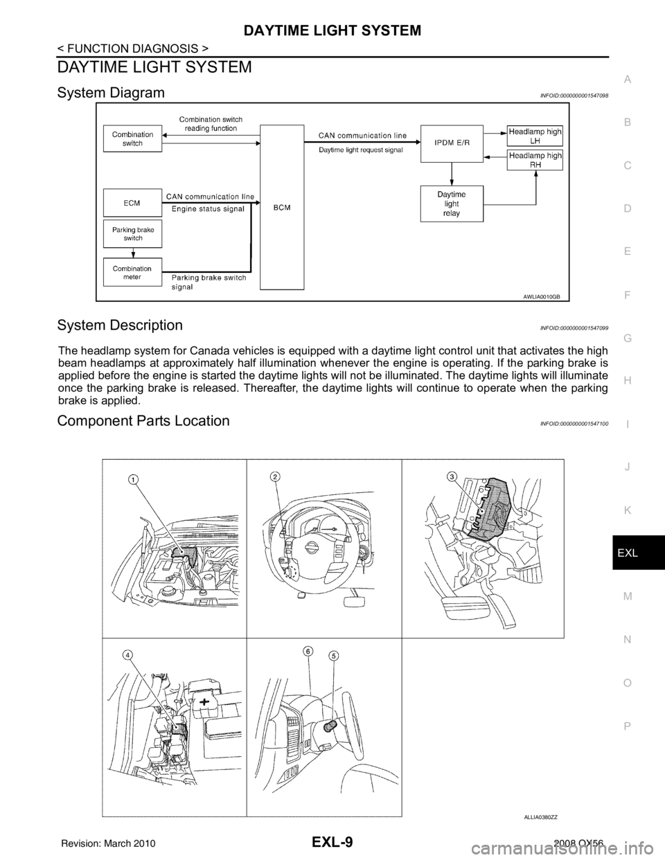
System DiagramINFOID:0000000001547098
System DescriptionINFOID:0000000001547099
The headlamp system for Canada vehicles is equipped with a daytime light control unit that activates the high
beam headlamps at approximately half illumination whenever the engine is operating. If the parking brake is
applied before the engine is started the daytime lights will not be illuminated. The daytime lights will illuminate
once the parking brake is released. Thereafter, the daytime lights will continue to operate when the parking
brake is applied.
Component Parts LocationINFOID:0000000001547100
AWLIA0010GB
ALLIA0380ZZ
Revision: March 2010 2008 QX56
Page 2186 of 4083

GI-44
< BASIC INSPECTION >
SERVICE INFORMATION FOR ELECTRICAL INCIDENT
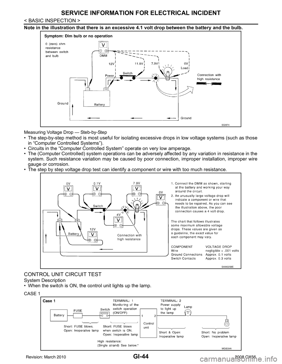
Note in the illustration that there is an excessive 4.1 volt drop between the battery and the bulb.
Measuring Voltage Drop — Steb-by-Step
• The step-by-step method is most useful for isolating excessive drops in low voltage systems (such as those
in “Computer Controlled Systems”).
• Circuits in the “Computer Controlled System” operate on very low amperage.
• The (Computer Controlled) system oper ations can be adversely affected by any variation in resistance in the
system. Such resistance variation may be caused by poor connection, improper installation, improper wire
gauge or corrosion.
• The step by step voltage drop test can identify a component or wire with too much resistance.
CONTROL UNIT CIRCUIT TEST
System Description
• When the switch is ON, the control unit lights up the lamp.
CASE 1
SGI974
SAIA0258E
MGI034A
Revision: March 2010 2008 QX56
Page 2669 of 4083

MWI-24
< FUNCTION DIAGNOSIS >
DIAGNOSIS SYSTEM (METER)
DIAGNOSIS SYSTEM (METER)
Diagnosis DescriptionINFOID:0000000001691283
SELF-DIAGNOSIS MODE
The following items can be checked during Combination Meter Self-Diagnosis Mode.
• Gauge sweep and present gauge values.
• Illuminates all odometer/trip meters and A/T indicator segments.
• Illuminates all micro controlled lamps/LEDs regardless of switch position.
• Displays estimated present battery voltage.
• Displays seat belt buckle switch LH status.
OPERATION PROCEDURE
NOTE:
• Once entered, combination meter self-diagnosis mode will function with the ignition switch in ON or START.
Combination meter self-diagnosis mode will exit upon turning the ignition switch to OFF or ACC.
• If the diagnosis function is activated with trip A displa yed, the mileage on trip A is reset to 0000.0. (Trip B
operates the same way.)
To initiate combination meter self-diagnosis mode, refer to the following procedure.
1. Turn the ignition switch ON, while pressing the odometer/trip meter switch for 5 - 8 \
seconds. When the diagnosis function is activated, the odometer/trip meter will display tESt.
NOTE:
Check combination meter power supply and ground circuit when self-diagnosis mode of combination meter
does not start. Refer to MWI-30, "
COMBINATION METER : Diagnosis Procedure". Replace combination
meter if normal. Refer to MWI-76, "
Removal and Installation".
COMBINATION METER SELF-DIAGNOSIS MODE FUNCTIONS
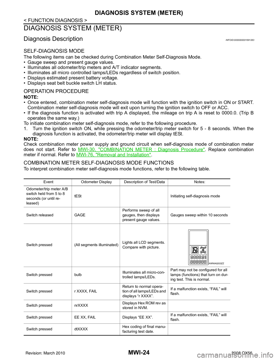
To interpret combination meter self-diagnosis mode functions, refer to the following table.
EventOdometer Display Description of Test/Data Notes:
Odometer/trip meter A/B
switch held from 5 to 8
seconds (or until re-
leased) tESt
Initiating self-diagnosis mode
Switch released GAGE Performs sweep of all
gauges, then displays
present gauge values.Gauges sweep within 10 seconds
Switch pressed (All segments illuminated) Lights all LCD segments.
Compare with picture.
Switch pressed bulbIlluminates all micro-con-
trolled lamps/LEDs. Part may not be configured for all
lamps (functions) th
at turn on dur-
ing test. This is normal.
Switch pressed r XXXX, FAIL Return to normal opera-
tion of all lamps/LEDs and
displays “r XXXX”.If a malfunction exists, “FAIL” will
flash.
Switch pressed nrXXXX Displays Hex ROM rev as
stored in NVM.
Switch pressed EE XX, FAIL Displays “EE XX”.If a malfunction exists, “FAIL” will
flash.
Switch pressed dtXXXX Hex coding of final manu-
facturing test date.
AWNIA0203ZZ
Revision: March 2010
2008 QX56
Page 2812 of 4083

PG
HARNESSPG-45
< COMPONENT DIAGNOSIS >
C
DE
F
G H
I
J
K L
B A
O P
N
C1 E5 W/24 : To F14
C1 E119 W/16: IPDM E/R (intelligent power distri-
bution module engine room)
C2 E7 GR/2 : Fusible link box (battery) D1 E120 W/6: IPDM E/R (intelligent power distri-
bution module engine room)
C2 E9 — : Body ground E1 E121 BR/12: IPDM E/R (intelligent power distri-
bution module engine room)
D4 E11 B/8 : Front combination lamp LH (without
daytime running lights) C1 E122 W/12: IPDM E/R (intelligent power distri-
bution module engine room)
D4 E11 B/8 : Front combination lamp LH (with
daytime running lights)
C1 E123 BR/8: IPDM E/R (intelligent power distri-
bution module engine room)
D3 E12 B/5 : Stop lamp relay D1 E124 W/6: IPDM E/R (intelligent power distri-
bution module engine room)
D4 E14 — : Body ground F3 E125 B/47: ABS actuator and electric unit
(control unit)
C2 E15 — : Body ground D4 E126 — : Body ground
C1 E16 B/40 : ECM C2 E130 W/2 : Compressor motor relay
E4 E18 GR/2 : Front wheel sensor LH C3 E131 W/2 : Compressor motor relay
D1 E19 W/16 : To F33 C3 E134 GR/6 : ICC brake hold relay
E3 E21 GR/2 : Brake fluid level switch C2 E135 GR/2 : Transfer dropping resister
E2 E23 GR/6 : Front wiper motor C1 E140 BR/6 : Trailer tow relay-2
D4 E24 — : Body ground B2 E153 W/2 : Transfer motor relay
F3 E25 BR/3 : Intelligent key warning buzzer B2 E154 W/2 : Transfer motor relay
C3 E27 BR/2 : Fusible link box (battery) D3 E156 L/4 : Trailer turn relay LH
C2 E30 /1 : Fusible link box (battery )D3 E157 L/4 : Trailer turn relay RH
E3 E31 B/3 : Front pressure sensor D5 E158 B/3 : Front sonar sensor LH outer
E3 E32 B/3 : Rear pressure sensor D5 E159 GR/3 : To E164
E1 E39 W/2 : To F34 B4 E160 GR/3 : To E165
D3 E40 B/3 : To E201 C3 E161 B/3 : Battery current sensor
D3 E41 SMJ : To C1 B4 E162 B/3 : Front sonar sensor LH inner
D3 E42 B/6 : ICC sensor C5 E163 B/3 : Front sonar sensor RH inner
E1 E46 B/5 : Transfer shift high relay D5 E164 GR/3 : To E159
D2 E47 B/5 : Transfer shift lo w relayA4 E165 GR/3 : To E160
C4 E48 B/3 : Refrigerant pressure sensor A3 E166 B/3 : Front sonar sensor RH outer
E3 E49 B/6 : Active booster Engine room sub-harness
D1 E69 L/4 : Transfer shut off relay D3 E201 B/3 : To E40
D5 E101 B/3 : Front turn-fog lamp LH C1 E202 /1 : Fusible link box (battery)
A4 E102 B/3 : Front turn-fog lamp RH C2 E203 — : Engine ground
C3 E103 B/5 : Daytime light relay C3 E204 /1 : Generator
D4 E105 BR/2 : Front and rear washer motor C3 E205 B/3 : Generator
E4 E106 BR/2 : Washer fluid level switch C3 E206 /1 : Generator
B3 E107 B/8 : Front combination lamp LH
C5 E113 W/2 : Cooling fan motor
Revision: March 2010 2008 QX56