2008 INFINITI QX56 boot
[x] Cancel search: bootPage 2630 of 4083
MA-32
< ON-VEHICLE MAINTENANCE >
CHASSIS AND BODY MAINTENANCE
• Check the axle and suspension nuts and bolts for looseness.
• Check the strut and shock absorber for oil leakage or other damage.
• Check the suspension ball joints for grease leakage and ball joint dust cover for cracks or other damage.
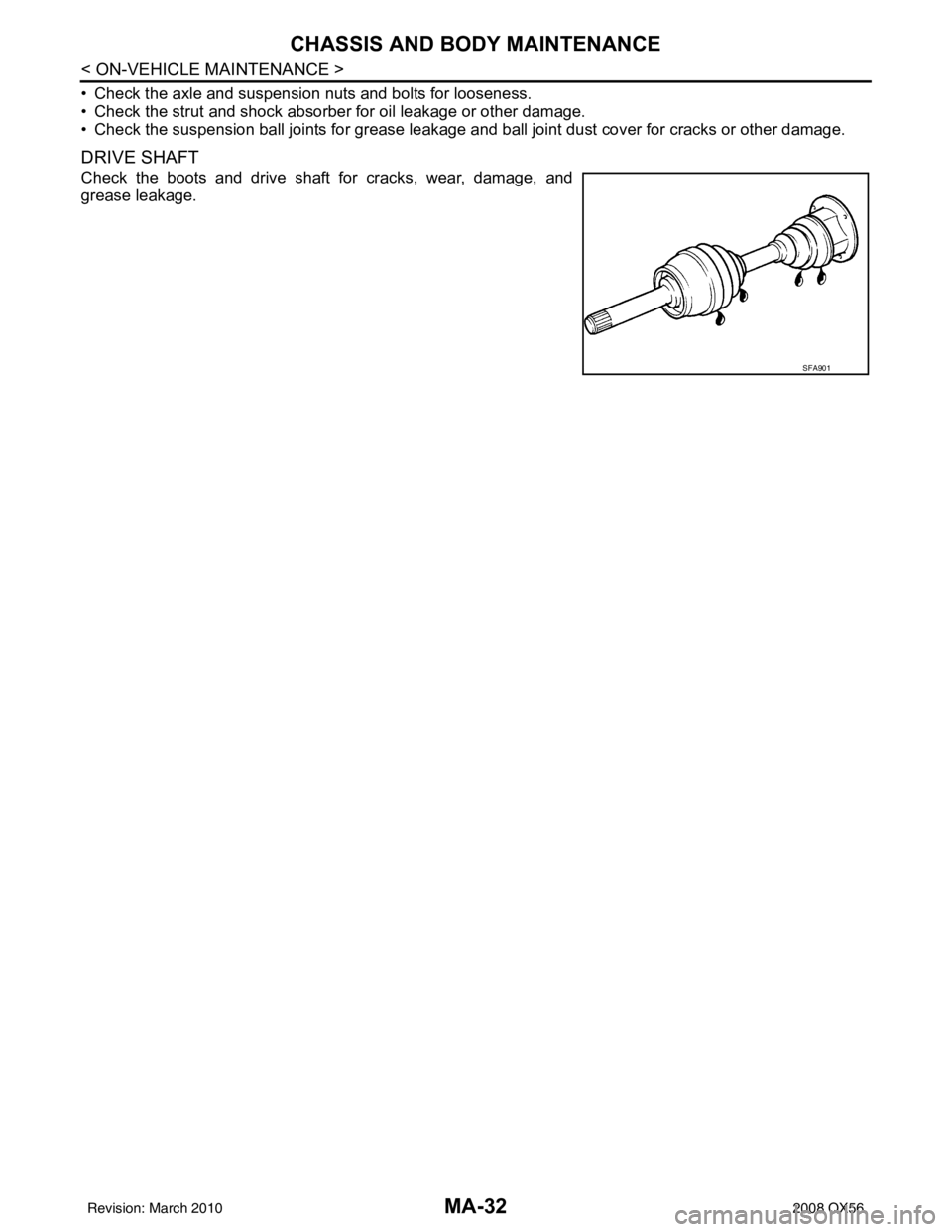
DRIVE SHAFT
Check the boots and drive shaft for cracks, wear, damage, and
grease leakage.
SFA901
Revision: March 20102008 QX56
Page 2969 of 4083
RAX-1
TRANSMISSION & DRIVELINE
CEF
G H
I
J
K L
M
SECTION RAX
A
B
RAX
N
O P
CONTENTS
REAR AXLE
PRECAUTION ....... ........................................2
PRECAUTIONS .............................................. .....2
Precaution for Supplemental Restraint System
(SRS) "AIR BAG" and "SEAT BELT PRE-TEN-
SIONER" ............................................................. ......
2
Precaution Necessary for Steering Wheel Rota-
tion After Battery Disconnect ............................... ......
2
Caution ......................................................................3
PREPARATION ............................................4
PREPARATION .............................................. .....4
Special Service Tool ........................................... ......4
Commercial Service Tool ..........................................4
SYMPTOM DIAGNOSIS ...............................5
NOISE, VIBRATION AND HARSHNESS
(NVH) TROUBLESHOOTING ........................ .....
5
NVH Troubleshooting Chart ................................ ......5
ON-VEHICLE MAINTENANCE .....................6
WHEEL HUB .................................................. .....6
On-Vehicle Inspection and Service ..................... ......6
ON-VEHICLE REPAIR ..................................7
REAR DRIVE SHAFT .........................................7
Component .......................................................... .....7
REMOVAL AND INSTALLATION ................8
WHEEL HUB ......................................................8
Removal and Installation ..................................... .....8
REAR DRIVE SHAFT ........................................10
Removal and Installation .........................................10
DISASSEMBLY AND ASSEMBLY ..............11
REAR DRIVE SHAFT ........................................11
Disassembly and Assembly ................................. ....11
SERVICE DATA AND SPECIFICATIONS
(SDS) ............... .......................................... ...
16
SERVICE DATA AND SPECIFICATIONS
(SDS) .................................................................
16
Wheel Bearing ..................................................... ....16
Drive Shaft ...............................................................16
Boot Bands ..............................................................16
Revision: March 2010 2008 QX56
Page 2972 of 4083
RAX-4
< PREPARATION >
PREPARATION
PREPARATION
PREPARATION
Special Service ToolINFOID:0000000001534573
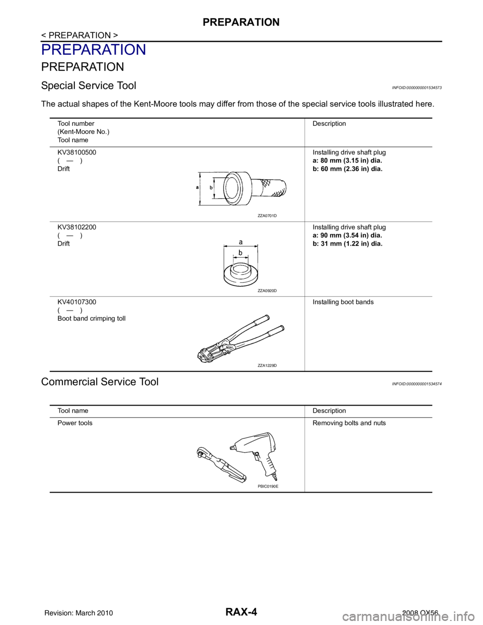
The actual shapes of the Kent-Moore tools may differ from those of the special service tools illustrated here.
Commercial Service ToolINFOID:0000000001534574
Tool number
(Kent-Moore No.)
Tool name Description
KV38100500
(—)
Drift Installing drive shaft plug
a: 80 mm (3.15 in) dia.
b: 60 mm (2.36 in) dia.
KV38102200
(—)
Drift Installing drive shaft plug
a: 90 mm (3.54 in) dia.
b: 31 mm (1.22 in) dia.
KV40107300
(—)
Boot band crimping toll Installing boot bands
ZZA0701D
ZZA0920D
ZZA1229D
Tool name
Description
Power tools Removing bolts and nuts
PBIC0190E
Revision: March 2010 2008 QX56
Page 2978 of 4083
RAX-10
< REMOVAL AND INSTALLATION >
REAR DRIVE SHAFT
REAR DRIVE SHAFT
Removal and InstallationINFOID:0000000001534612
REMOVAL
1. Remove the wheel and tire using power tool.
2. Remove the stabilizer bar clamp. Refer to RSU-9, "
Component".
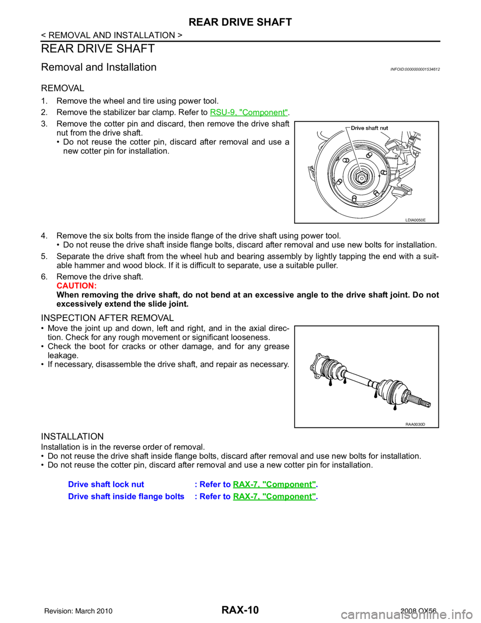
3. Remove the cotter pin and discard, then remove the drive shaft nut from the drive shaft.
• Do not reuse the cotter pin, discard after removal and use anew cotter pin for installation.
4. Remove the six bolts from the inside flange of the drive shaft using power tool. • Do not reuse the drive shaft inside flange bolts, discard after removal and use new bolts for installation.
5. Separate the drive shaft from the wheel hub and bearing assembly by lightly tapping the end with a suit- able hammer and wood block. If it is difficult to separate, use a suitable puller.
6. Remove the drive shaft. CAUTION:
When removing the drive shaft, do not bend at an excessive angle to the drive shaft joint. Do not
excessively extend the slide joint.
INSPECTION AFTER REMOVAL
• Move the joint up and down, left and right, and in the axial direc- tion. Check for any rough movement or significant looseness.
• Check the boot for cracks or other damage, and for any grease leakage.
• If necessary, disassemble the drive shaft, and repair as necessary.
INSTALLATION
Installation is in the reverse order of removal.
• Do not reuse the drive shaft inside flange bolts, discard after removal and use new bolts for installation.
• Do not reuse the cotter pin, discard after removal and use a new cotter pin for installation.
LDIA0050E
RAA0030D
Drive shaft lock nut : Refer to RAX-7, "Component".
Drive shaft inside flange bolts : Refer to RAX-7, "
Component".
Revision: March 2010 2008 QX56
Page 2979 of 4083
REAR DRIVE SHAFTRAX-11
< DISASSEMBLY AND ASSEMBLY >
CEF
G H
I
J
K L
M A
B
RAX
N
O P
DISASSEMBLY AND ASSEMBLY
REAR DRIVE SHAFT
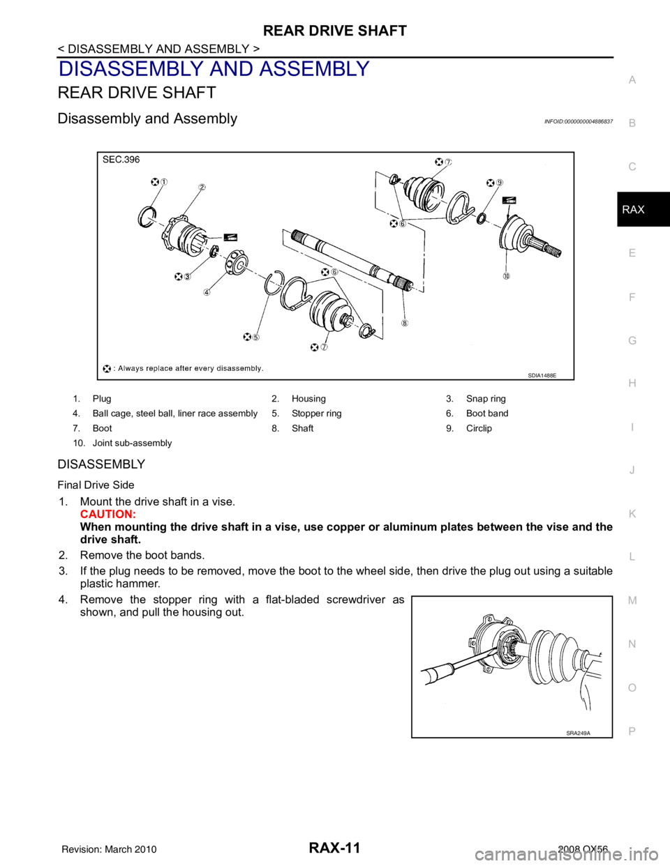
Disassembly and AssemblyINFOID:0000000004886837
DISASSEMBLY
Final Drive Side
1. Mount the drive shaft in a vise. CAUTION:
When mounting the drive shaft in a vise, use co pper or aluminum plates between the vise and the
drive shaft.
2. Remove the boot bands.
3. If the plug needs to be removed, move the boot to t he wheel side, then drive the plug out using a suitable
plastic hammer.
4. Remove the stopper ring with a flat-bladed screwdriver as shown, and pull the housing out.
1. Plug 2. Housing3. Snap ring
4. Ball cage, steel ball, liner race assembly 5. Stopper ring 6. Boot band
7. Boot 8. Shaft9. Circlip
10. Joint sub-assembly
SDIA1488E
SRA249A
Revision: March 2010 2008 QX56
Page 2980 of 4083
RAX-12
< DISASSEMBLY AND ASSEMBLY >
REAR DRIVE SHAFT
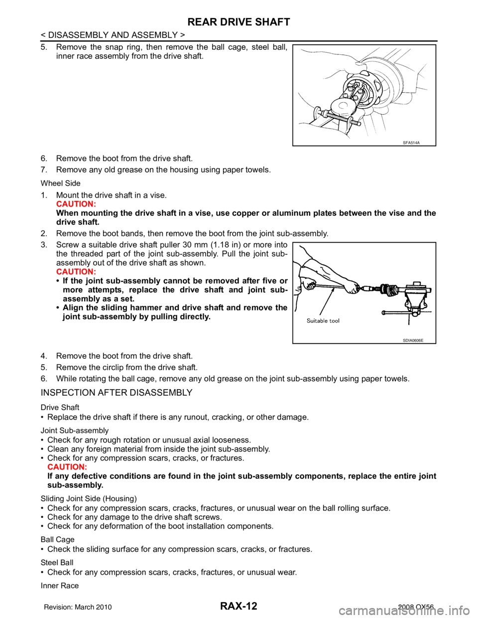
5. Remove the snap ring, then remove the ball cage, steel ball,inner race assembly from the drive shaft.
6. Remove the boot from the drive shaft.
7. Remove any old grease on the housing using paper towels.
Wheel Side
1. Mount the drive shaft in a vise. CAUTION:
When mounting the drive shaft in a vise, use copp er or aluminum plates between the vise and the
drive shaft.
2. Remove the boot bands, then remove the boot from the joint sub-assembly.
3. Screw a suitable drive shaft puller 30 mm (1.18 in) or more into the threaded part of the joint sub-assembly. Pull the joint sub-
assembly out of the drive shaft as shown.
CAUTION:
• If the joint sub-assembly cannot be removed after five ormore attempts, replace the drive shaft and joint sub-
assembly as a set.
• Align the sliding hammer and drive shaft and remove the
joint sub-assembly by pulling directly.
4. Remove the boot from the drive shaft.
5. Remove the circlip from the drive shaft.
6. While rotating the ball cage, remove any old grease on the joint sub-assembly using paper towels.
INSPECTION AFTER DISASSEMBLY
Drive Shaft
• Replace the drive shaft if there is any runout, cracking, or other damage.
Joint Sub-assembly
• Check for any rough rotation or unusual axial looseness.
• Clean any foreign material from inside the joint sub-assembly.
• Check for any compression scars, cracks, or fractures.
CAUTION:
If any defective conditions are found in the joint sub-assembly comp onents, replace the entire joint
sub-assembly.
Sliding Joint Side (Housing)
• Check for any compression scars, cracks, fracture s, or unusual wear on the ball rolling surface.
• Check for any damage to the drive shaft screws.
• Check for any deformation of the boot installation components.
Ball Cage
• Check the sliding surface for any compression scars, cracks, or fractures.
Steel Ball
• Check for any compression scars, cr acks, fractures, or unusual wear.
Inner Race
SFA514A
SDIA0606E
Revision: March 2010 2008 QX56
Page 2981 of 4083
REAR DRIVE SHAFTRAX-13
< DISASSEMBLY AND ASSEMBLY >
CEF
G H
I
J
K L
M A
B
RAX
N
O P
• Check the ball sliding surface for any co mpression scars, cracks, or fractures.
• Check for any damage to the serrated part. CAUTION:
If any defective conditions are found, install a new housing, ball cage, steel ball, and inner race as a
set.
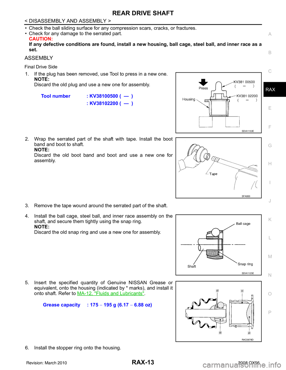
ASSEMBLY
Final Drive Side
1. If the plug has been removed, use Tool to press in a new one. NOTE:
Discard the old plug and use a new one for assembly.
2. Wrap the serrated part of the shaft with tape. Install the boot band and boot to shaft.
NOTE:
Discard the old boot band and boot and use a new one for
assembly.
3. Remove the tape wound around the serrated part of the shaft.
4. Install the ball cage, steel ball, and inner race assembly on the shaft, and secure them tightly using the snap ring.
NOTE:
Discard the old snap ring and use a new one for assembly.
5. Insert the specified quantity of Genuine NISSAN Grease or equivalent, onto the housing (indicated by * marks), and install it
onto shaft. Refer to MA-12, "
Fluids and Lubricants".
6. Install the stopper ring onto the housing. Tool number : KV38100500 ( — )
: KV38102200 ( — )
SDIA1153E
SFA800
SDIA1125E
Grease capacity : 175 − 195 g (6.17 − 6.88 oz)
RAC0678D
Revision: March 2010 2008 QX56
Page 2982 of 4083
RAX-14
< DISASSEMBLY AND ASSEMBLY >
REAR DRIVE SHAFT
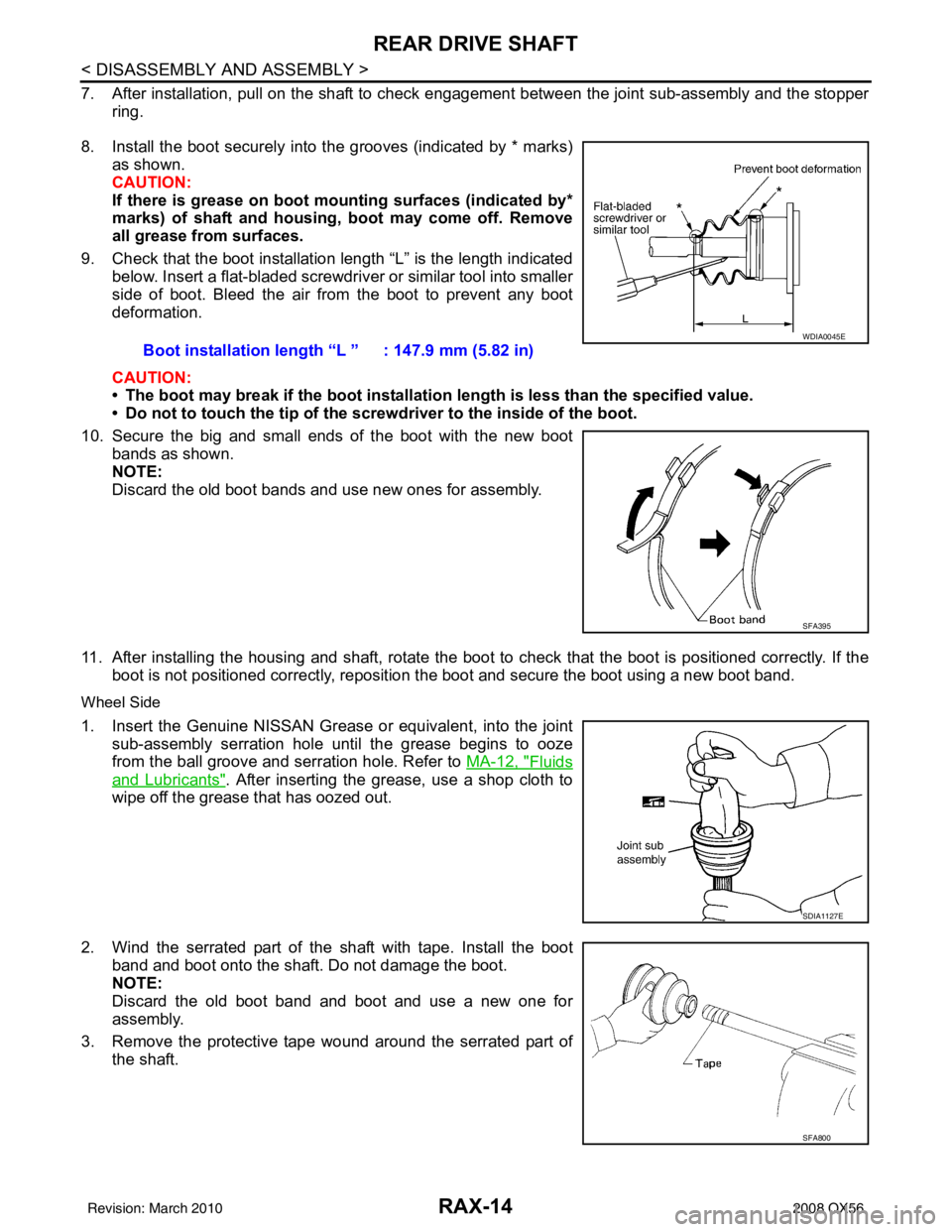
7. After installation, pull on the shaft to check engagement between the joint sub-assembly and the stopper
ring.
8. Install the boot securely into the grooves (indicated by * marks) as shown.
CAUTION:
If there is grease on boot mo unting surfaces (indicated by*
marks) of shaft and housing, boot may come off. Remove
all grease from surfaces.
9. Check that the boot installation length “L” is the length indicated below. Insert a flat-bladed screwdriver or similar tool into smaller
side of boot. Bleed the air from the boot to prevent any boot
deformation.
CAUTION:
• The boot may break if the boot installation length is less than the specified value.
• Do not to touch the tip of the screw driver to the inside of the boot.
10. Secure the big and small ends of the boot with the new boot bands as shown.
NOTE:
Discard the old boot bands and use new ones for assembly.
11. After installing the housing and shaft, rotate the boot to check that the boot is positioned correctly. If the boot is not positioned correctly, reposition t he boot and secure the boot using a new boot band.
Wheel Side
1. Insert the Genuine NISSAN Grease or equivalent, into the joint
sub-assembly serration hole until the grease begins to ooze
from the ball groove and serration hole. Refer to MA-12, "
Fluids
and Lubricants". After inserting the grease, use a shop cloth to
wipe off the grease that has oozed out.
2. Wind the serrated part of the shaft with tape. Install the boot
band and boot onto the shaft. Do not damage the boot.
NOTE:
Discard the old boot band and boot and use a new one for
assembly.
3. Remove the protective tape wound around the serrated part of the shaft. Boot installation length
“L ” : 147.9 mm (5.82 in)
WDIA0045E
SFA395
SDIA1127E
SFA800
Revision: March 2010 2008 QX56