2008 INFINITI QX56 recommended oil
[x] Cancel search: recommended oilPage 1808 of 4083
PRECAUTIONSEM-5
< PRECAUTION >
C
DE
F
G H
I
J
K L
M A
EM
NP
O
Precaution for Liquid GasketINFOID:0000000001538800
REMOVAL OF LIQUID GASKET SEALING
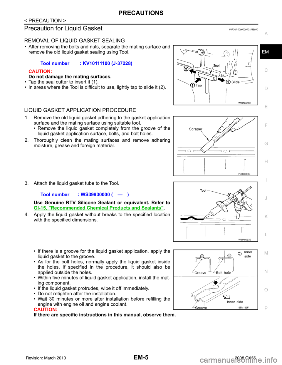
• After removing the bolts and nuts, separate the mating surface and
remove the old liquid gasket sealing using Tool.
CAUTION:
Do not damage the mating surfaces.
• Tap the seal cutter to insert it (1).
• In areas where the Tool is difficult to use, lightly tap to slide it (2).
LIQUID GASKET APPLICATION PROCEDURE
1. Remove the old liquid gasket adhering to the gasket application surface and the mating surface using suitable tool.
• Remove the liquid gasket completely from the groove of the
liquid gasket application surface, bolts, and bolt holes.
2. Thoroughly clean the mating surfaces and remove adhering moisture, grease and foreign material.
3. Attach the liquid gasket tube to the Tool. Use Genuine RTV Silicone Sealant or equivalent. Refer to
GI-15, "
Recommended Chemical Products and Sealants".
4. Apply the liquid gasket without breaks to the specified location with the specified dimensions.
• If there is a groove for the liquid gasket application, apply theliquid gasket to the groove.
• As for the bolt holes, normally apply the liquid gasket inside
the holes. If specified in the procedure, it should also be
applied outside the holes.
• Within five minutes of liquid gasket application, install the mat-
ing component.
• If the liquid gasket protrudes, wipe it off immediately.
• Do not retighten after the installation.
• Wait 30 minutes or more after installation before refilling the engine with engine oil and engine coolant.
CAUTION:
If there are specific instructions in this manual, observe them.
Tool number : KV10111100 (J-37228)
WBIA0566E
PBIC0003E
Tool number : WS39930000 ( — )
WBIA0567E
SEM159F
Revision: March 2010
2008 QX56
Page 1831 of 4083
EM-28
< ON-VEHICLE REPAIR >
INTAKE MANIFOLD
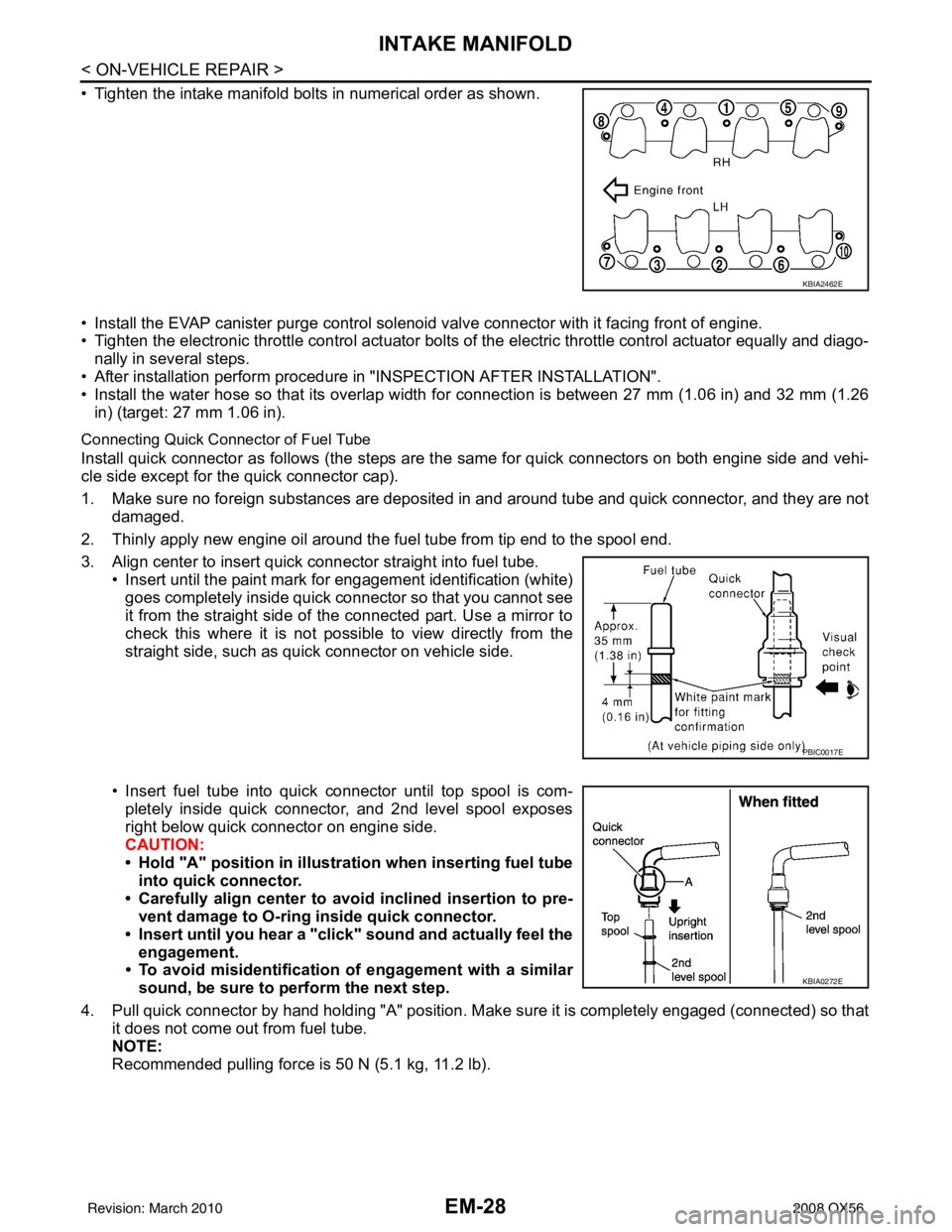
• Tighten the intake manifold bolts in numerical order as shown.
• Install the EVAP canister purge control solenoid valve connector with it facing front of engine.
• Tighten the electronic throttle control actuator bolts of the electric throttle control actuator equally and diago-
nally in several steps.
• After installation perform procedure in "INSPECTION AFTER INSTALLATION".
• Install the water hose so that its overlap width for connection is between 27 mm (1.06 in) and 32 mm (1.26 in) (target: 27 mm 1.06 in).
Connecting Quick Connector of Fuel Tube
Install quick connector as follows (the steps are t he same for quick connectors on both engine side and vehi-
cle side except for the quick connector cap).
1. Make sure no foreign substances are deposited in and around tube and quick connector, and they are not damaged.
2. Thinly apply new engine oil around the fuel tube from tip end to the spool end.
3. Align center to insert quick connector straight into fuel tube. • Insert until the paint mark for engagement identification (white)goes completely inside quick connector so that you cannot see
it from the straight side of the connected part. Use a mirror to
check this where it is not possible to view directly from the
straight side, such as quick connector on vehicle side.
• Insert fuel tube into quick connector until top spool is com- pletely inside quick connector, and 2nd level spool exposes
right below quick connector on engine side.
CAUTION:
• Hold "A" position in illustration when inserting fuel tubeinto quick connector.
• Carefully align center to avoid inclined insertion to pre-
vent damage to O-ring inside quick connector.
• Insert until you hear a "click" sound and actually feel the
engagement.
• To avoid misidentification of engagement with a similar
sound, be sure to pe rform the next step.
4. Pull quick connector by hand holding "A" position. Make sure it is completely engaged (connected) so that
it does not come out from fuel tube.
NOTE:
Recommended pulling force is 50 N (5.1 kg, 11.2 lb).
KBIA2462E
PBIC0017E
KBIA0272E
Revision: March 2010 2008 QX56
Page 1838 of 4083
OIL PAN AND OIL STRAINEREM-35
< ON-VEHICLE REPAIR >
C
DE
F
G H
I
J
K L
M A
EM
NP
O
1. Install the oil pan (upper) using the following steps.
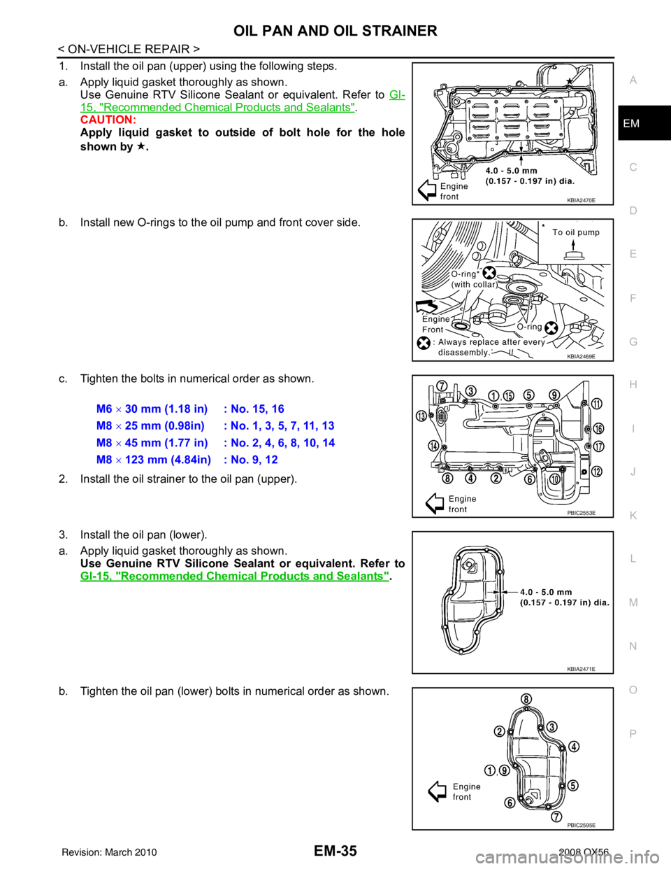
a. Apply liquid gasket thoroughly as shown.
Use Genuine RTV Silicone Sealant or equivalent. Refer to GI-
15, "Recommended Chemical Products and Sealants".
CAUTION:
Apply liquid gasket to outside of bolt hole for the hole
shown by .
b. Install new O-rings to the oil pump and front cover side.
c. Tighten the bolts in numerical order as shown.
2. Install the oil strainer to the oil pan (upper).
3. Install the oil pan (lower).
a. Apply liquid gasket thoroughly as shown. Use Genuine RTV Silicone Seal ant or equivalent. Refer to
GI-15, "
Recommended Chemical Products and Sealants".
b. Tighten the oil pan (lower) bolts in numerical order as shown.
KBIA2470E
KBIA2469E
M6 × 30 mm (1.18 in) : No. 15, 16
M8 × 25 mm (0.98in) : No. 1, 3, 5, 7, 11, 13
M8 × 45 mm (1.77 in) : No. 2, 4, 6, 8, 10, 14
M8 × 123 mm (4.84in) : No. 9, 12
PBIC2553E
KBIA2471E
PBIC2595E
Revision: March 2010 2008 QX56
Page 1842 of 4083
ROCKER COVEREM-39
< ON-VEHICLE REPAIR >
C
DE
F
G H
I
J
K L
M A
EM
NP
O
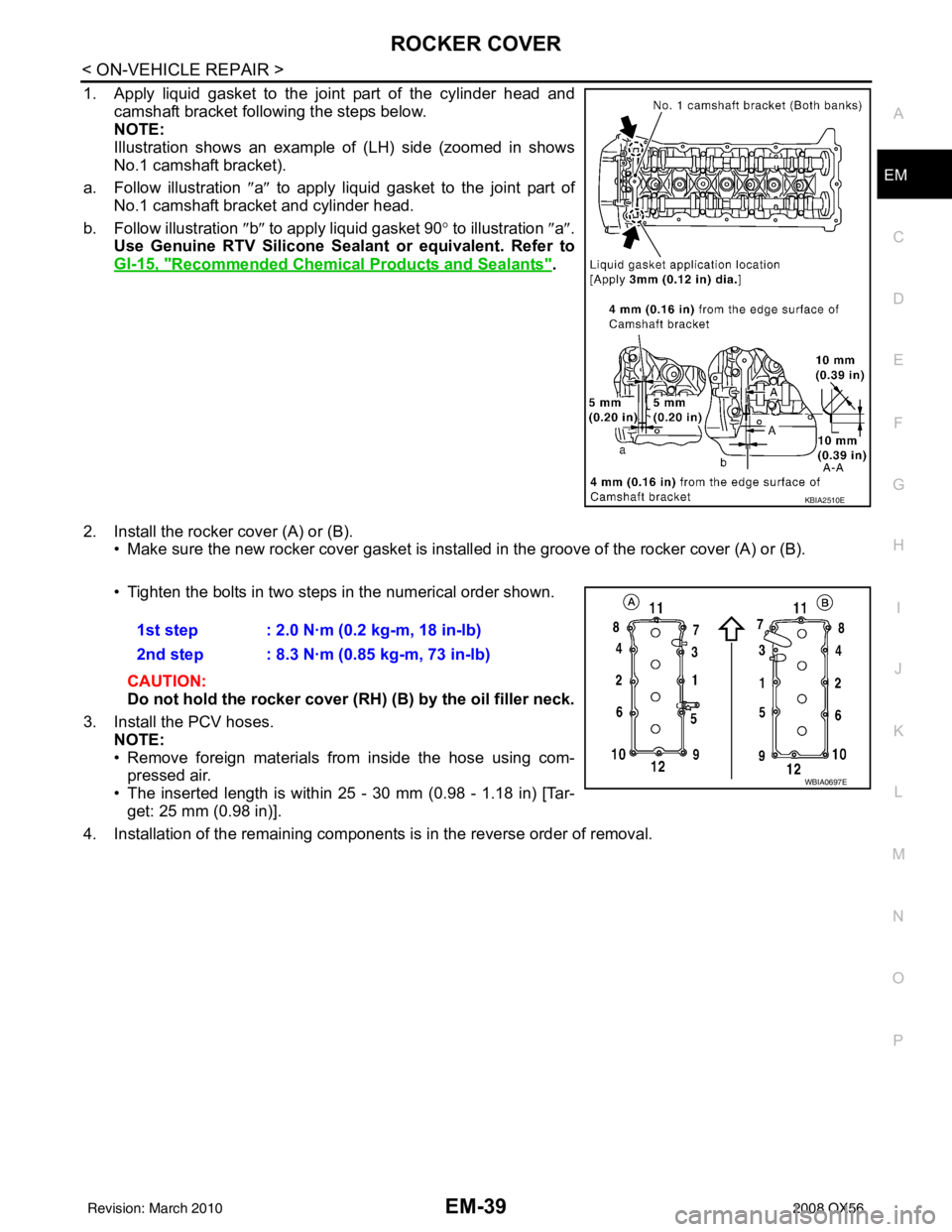
1. Apply liquid gasket to the joint part of the cylinder head and
camshaft bracket following the steps below.
NOTE:
Illustration shows an example of (LH) side (zoomed in shows
No.1 camshaft bracket).
a. Follow illustration ″a ″ to apply liquid gasket to the joint part of
No.1 camshaft bracket and cylinder head.
b. Follow illustration ″b ″ to apply liquid gasket 90 ° to illustration ″ a″.
Use Genuine RTV Silicone Seal ant or equivalent. Refer to
GI-15, "
Recommended Chemical Products and Sealants".
2. Install the rocker cover (A) or (B). • Make sure the new rocker cover gasket is install ed in the groove of the rocker cover (A) or (B).
• Tighten the bolts in two steps in the numerical order shown.
CAUTION:
Do not hold the rocker cover ( RH) (B) by the oil filler neck.
3. Install the PCV hoses. NOTE:
• Remove foreign materials from inside the hose using com-
pressed air.
• The inserted length is within 25 - 30 mm (0.98 - 1.18 in) [Tar-
get: 25 mm (0.98 in)].
4. Installation of the remaining components is in the reverse order of removal.
KBIA2510E
1st step : 2.0 N·m (0.2 kg-m, 18 in-lb)
2nd step : 8.3 N·m (0.85 kg-m, 73 in-lb)
WBIA0697E
Revision: March 2010 2008 QX56
Page 1853 of 4083
EM-50
< ON-VEHICLE REPAIR >
TIMING CHAIN
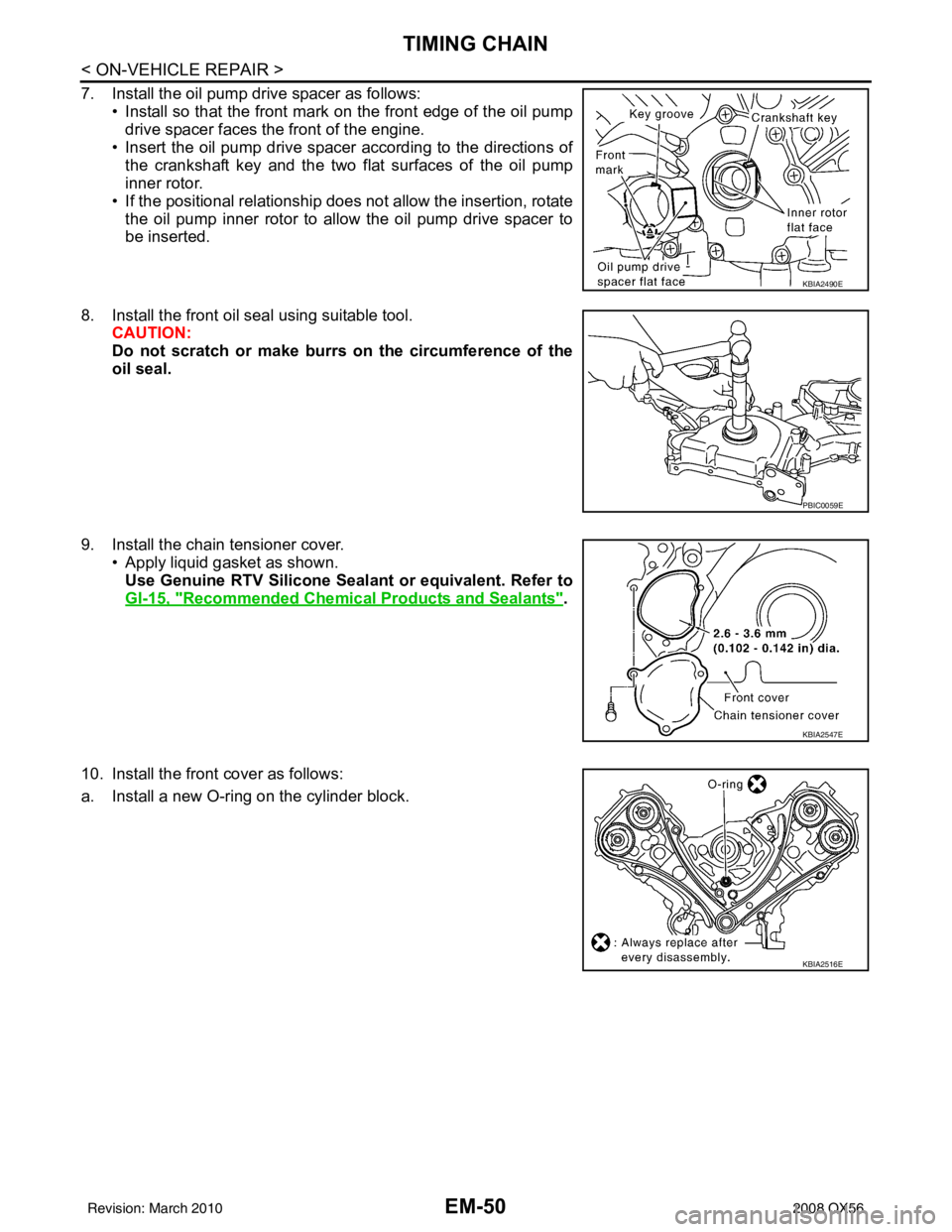
7. Install the oil pump drive spacer as follows:• Install so that the front mark on the front edge of the oil pumpdrive spacer faces the front of the engine.
• Insert the oil pump drive spacer according to the directions of the crankshaft key and the two flat surfaces of the oil pump
inner rotor.
• If the positional relationship does not allow the insertion, rotate the oil pump inner rotor to allow the oil pump drive spacer to
be inserted.
8. Install the front oil seal using suitable tool. CAUTION:
Do not scratch or make burrs on the circumference of the
oil seal.
9. Install the chain tensioner cover. • Apply liquid gasket as shown.
Use Genuine RTV Silicone Seal ant or equivalent. Refer to
GI-15, "
Recommended Chemical Products and Sealants".
10. Install the front cover as follows:
a. Install a new O-ring on the cylinder block.
KBIA2490E
PBIC0059E
KBIA2547E
KBIA2516E
Revision: March 2010 2008 QX56
Page 1854 of 4083
TIMING CHAINEM-51
< ON-VEHICLE REPAIR >
C
DE
F
G H
I
J
K L
M A
EM
NP
O
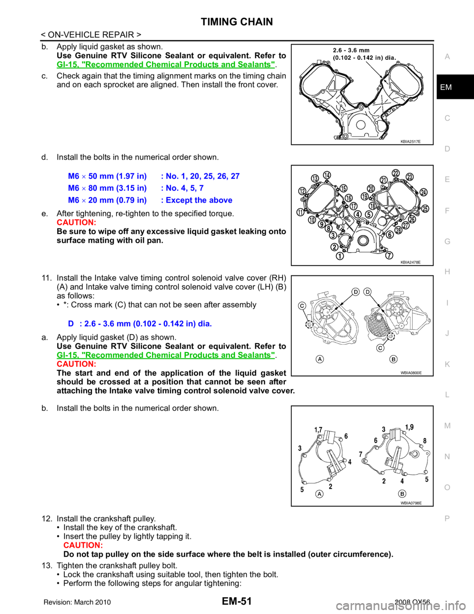
b. Apply liquid gasket as shown.
Use Genuine RTV Silicone Seal ant or equivalent. Refer to
GI-15, "
Recommended Chemical Products and Sealants".
c. Check again that the timing alignment marks on the timing chain and on each sprocket are aligned. Then install the front cover.
d. Install the bolts in the numerical order shown.
e. After tightening, re-tighten to the specified torque. CAUTION:
Be sure to wipe off any excessive liquid gasket leaking onto
surface mating with oil pan.
11. Install the Intake valve timing control solenoid valve cover (RH) (A) and Intake valve timing control solenoid valve cover (LH) (B)
as follows:
• *: Cross mark (C) that can not be seen after assembly
a. Apply liquid gasket (D) as shown. Use Genuine RTV Silicone Seal ant or equivalent. Refer to
GI-15, "
Recommended Chemical Products and Sealants".
CAUTION:
The start and end of the appl ication of the liquid gasket
should be crossed at a positi on that cannot be seen after
attaching the Intake valve timing control solenoid valve cover.
b. Install the bolts in the numerical order shown.
12. Install the crankshaft pulley. • Install the key of the crankshaft.
• Insert the pulley by lightly tapping it.
CAUTION:
Do not tap pulley on the side surface where th e belt is installed (outer circumference).
13. Tighten the crankshaft pulley bolt. • Lock the crankshaft using suitable tool, then tighten the bolt.
• Perform the following steps for angular tightening:
KBIA2517E
M6 × 50 mm (1.97 in) : No. 1, 20, 25, 26, 27
M6 × 80 mm (3.15 in) : No. 4, 5, 7
M6 × 20 mm (0.79 in) : Except the above
KBIA2478E
D : 2.6 - 3.6 mm (0.102 - 0.142 in) dia.
WBIA0800E
WBIA0798E
Revision: March 2010 2008 QX56
Page 1865 of 4083
EM-62
< ON-VEHICLE REPAIR >
CAMSHAFT
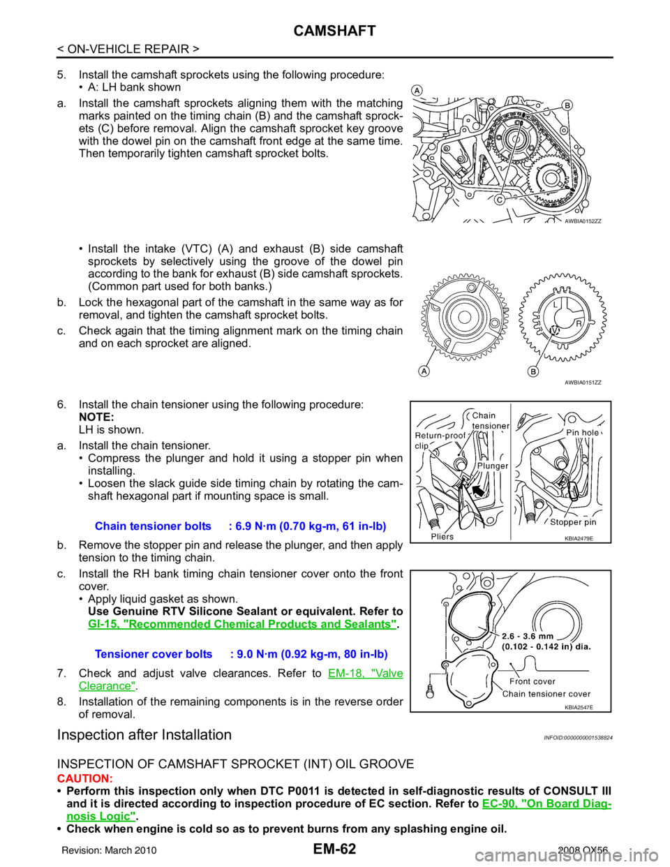
5. Install the camshaft sprockets using the following procedure:• A: LH bank shown
a. Install the camshaft sprockets aligning them with the matching marks painted on the timing chain (B) and the camshaft sprock-
ets (C) before removal. Align the camshaft sprocket key groove
with the dowel pin on the camshaft front edge at the same time.
Then temporarily tighten camshaft sprocket bolts.
• Install the intake (VTC) (A) and exhaust (B) side camshaft
sprockets by selectively using the groove of the dowel pin
according to the bank for exhaust (B) side camshaft sprockets.
(Common part used for both banks.)
b. Lock the hexagonal part of the camshaft in the same way as for removal, and tighten the camshaft sprocket bolts.
c. Check again that the timing alignment mark on the timing chain and on each sprocket are aligned.
6. Install the chain tensioner using the following procedure: NOTE:
LH is shown.
a. Install the chain tensioner. • Compress the plunger and hold it using a stopper pin when
installing.
• Loosen the slack guide side timing chain by rotating the cam- shaft hexagonal part if mounting space is small.
b. Remove the stopper pin and release the plunger, and then apply tension to the timing chain.
c. Install the RH bank timing chain tensioner cover onto the front cover.
• Apply liquid gasket as shown.Use Genuine RTV Silicone Seal ant or equivalent. Refer to
GI-15, "
Recommended Chemical Products and Sealants".
7. Check and adjust valve clearances. Refer to EM-18, "
Va l v e
Clearance".
8. Installation of the remaining components is in the reverse order of removal.
Inspection after InstallationINFOID:0000000001538824
INSPECTION OF CAMSHAFT SPROCKET (INT) OIL GROOVE
CAUTION:
• Perform this inspection only when DTC P0011 is detected in self-diagnostic results of CONSULT III
and it is directed accordi ng to inspection procedure of EC section. Refer to EC-90, "
On Board Diag-
nosis Logic".
• Check when engine is cold so as to pr event burns from any splashing engine oil.
AWBIA0152ZZ
AWBIA0151ZZ
Chain tensioner bolts : 6.9 N·m (0.70 kg-m, 61 in-lb)
Tensioner cover bolts : 9.0 N·m (0.92 kg-m, 80 in-lb)KBIA2479E
KBIA2547E
Revision: March 2010 2008 QX56
Page 1875 of 4083
EM-72
< ON-VEHICLE REPAIR >
CYLINDER HEAD
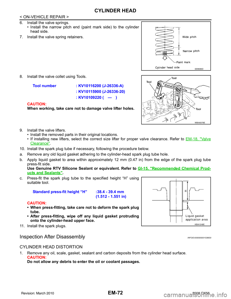
6. Install the valve springs.• Install the narrow pitch end (paint mark side) to the cylinderhead side.
7. Install the valve spring retainers.
8. Install the valve collet using Tools.
CAUTION:
When working, take care not to damage valve lifter holes.
9. Install the valve lifters. • Install the removed parts in their original locations.
• If installing new lifters, select the correct size lifter for proper valve clearance. Refer to EM-18, "
Va l v e
Clearance".
10. Install the spark plug tube if necessary, following the procedure below.
a. Remove any old liquid gasket adhering to the cylinder-head spark plug tube hole.
b. Apply liquid gasket to area within approximately 12 mm (0.47 in) from the edge of the spark plug tube
press-fit side.
Use Genuine RTV Silicone Seal ant or equivalent. Refer to GI-15, "
Recommended Chemical Prod-
ucts and Sealants".
c. Press-fit the spark plug tube to the specified height “H” using suitable tool.
CAUTION:
• When press-fitting, take care not to deform the spark plugtube.
• After press-fitting, wipe off any liquid gasket protruding
onto the cylinder-head upper face.
11. Install the spark plugs.
Inspection After DisassemblyINFOID:0000000001538830
CYLINDER HEAD DISTORTION
1. Remove any oil, scale, gasket, sealant and carbon deposits from the cylinder head surface. CAUTION:
Do not allow any debris to en ter the oil or coolant passages.
SEM085D
Tool number : KV10116200 (J-26336-A)
: KV10115900 (J-26336-20)
: KV10109220 ( — )
WBIA0578E
Standard press-fit height “H” :38.4 - 39.4 mm (1.512 - 1.551 in)
KBIA1248E
Revision: March 2010 2008 QX56